tow BMW 325I TOURING 2005 E46 User Guide
[x] Cancel search | Manufacturer: BMW, Model Year: 2005, Model line: 325I TOURING, Model: BMW 325I TOURING 2005 E46Pages: 178, PDF Size: 2.69 MB
Page 102 of 178
102
Tips for pleasant drivingUse the automatic mode by pressing
AUTO button 6. Select an interior tem-
perature that is comfortable for you.
Detailed setting options are described
for you in the following section.
You can make the settings of your
vehicle in such a manner that
when you unlock the vehicle with the
remote control of your personal key,
your own personalized setting for the
automatic climate control is initiated.
The AUTO program adjusts the
air distribution and the air sup-
ply for you and in addition adapts the
temperature to external influences –
summer, winter – to meet preferences
you can specify.
Individual air distribution
You can cancel the AUTO pro-
gram by selecting specific dis-
tribution patterns to suit your
own individual requirements.
While the AUTO program is then deacti-
vated, the automatic airflow control
remains in operation. Air flows onto
windows , toward the upper body
, and into the footwell . You can
switch the automatic distribution of air
back on by selecting the AUTO button.Temperature
The interior temperature that
appears in the display panel is a
general figure intended for refer-
ence purposes. We recommend
727/+226 as a comfortable setting,
even if the air conditioning is on. When
you start the vehicle, the system
ensures that the selected temperature
is achieved as quickly as possible
regardless of the season. It then main-
tains this temperature.
To select the units of measure 6/7 of
the display, refer to page 83.
Air supply/Blower
By pressing the upper or lower
button, you can vary the air sup-
ply. This deactivates the auto-
matic control of the air supply, AUTO
disappears from the display panel. Nev-
ertheless, the automatic air distribution
remains unchanged. You can reactivate
the automatic air distribution mode by
selecting the AUTO button.
When the lowest blower speed is set
and you press the lower button, all of
the displays are canceled: the blower,
heating and air conditioning are
switched off. The outside air supply is
blocked. You can reactivate the system
by pressing any button for the auto-
matic climate control.To defrost windows and remove
condensation
This program quickly removes
ice and condensation from the
windshield and the side windows.
Air conditioning
The air is cooled and dehumidi-
fied and – depending on the
temperature setting – rewarmed.
Depending on the weather, the wind-
shield may fog over briefly when the
engine is started. Air conditioning helps
prevent the windows from fogging up.
Condensation forms during opera-
tion of the air conditioning system,
which then exits under the vehicle. It is
thus not unusual for a small puddle to
form under the car while the system is
running.<
Automatic climate control*
Page 112 of 178
112
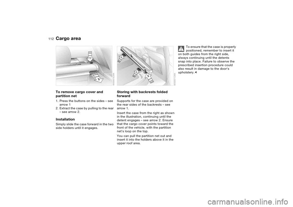
To remove cargo cover and
partition net1. Press the buttons on the sides – see
arrow 1
2. Extract the case by pulling to the rear
– see arrow 2.InstallationSimply slide the case forward in the two
side holders until it engages.
Storing with backrests folded
forwardSupports for the case are provided on
the rear sides of the backrests – see
arrow 1.
Insert the case from the right as shown
in the illustration, continuing until the
detent engages – see arrow 2. Ensure
that the cargo cover points toward the
front of the vehicle, with the partition
net's loop on the top.
You can pull the partition net out and
insert it into the holders above it in the
upper roof area.
To ensure that the case is properly
positioned, remember to insert it
on both guides from the right side,
always continuing until the detents
snap into place. Failure to observe the
prescribed insertion procedure could
also result in damage to the door's
upholstery.<
Cargo area
Page 114 of 178
114
Determining the maximum load1. Locate the following statement on
your vehicle‘s placard*:
The combined weight of occu-
pants and cargo should never
exceed XXX kg or YYY lbs., as this
could otherwise result in damage to the
vehicle or unstable driving conditions.<
2. Determine the combined weight of
the driver and passengers that will be
riding in your vehicle
3. Subtract the combined weight of the
driver and passengers from
XXX kilograms or YYY pounds
4. The resulting figure equals the avail-
able amount of cargo and luggage
load capacity.
For example, if the XXX amount
equals 1,400 lbs. and there will be
five 150 lbs. passengers in your vehi-
cle, the amount of available cargo
and luggage load capacity is
650 lbs.:
1,400 lbs. minus 750 lbs. = 650 lbs.
5. Determine the combined weight of
luggage and cargo being loaded on
the vehicle. That weight may not
safely exceed the available cargo
and luggage load capacity calculated
in Step 4
6. If your vehicle will be towing a trailer,
load from your trailer will be trans-
fered to your vehicle. Consult the
manual for transporting a trailer to
determine how this may reduce the
available cargo and luggage load
capacity of your vehicle.
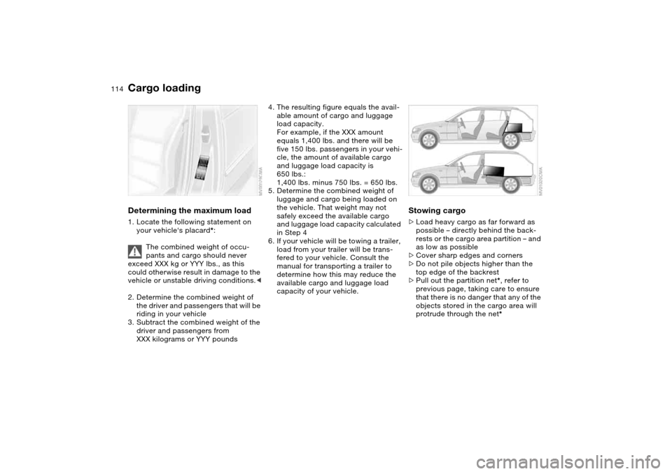
Stowing cargo>Load heavy cargo as far forward as
possible – directly behind the back-
rests or the cargo area partition – and
as low as possible
>Cover sharp edges and corners
>Do not pile objects higher than the
top edge of the backrest
>Pull out the partition net*, refer to
previous page, taking care to ensure
that there is no danger that any of the
objects stored in the cargo area will
protrude through the net*
Cargo loading
Page 115 of 178
115
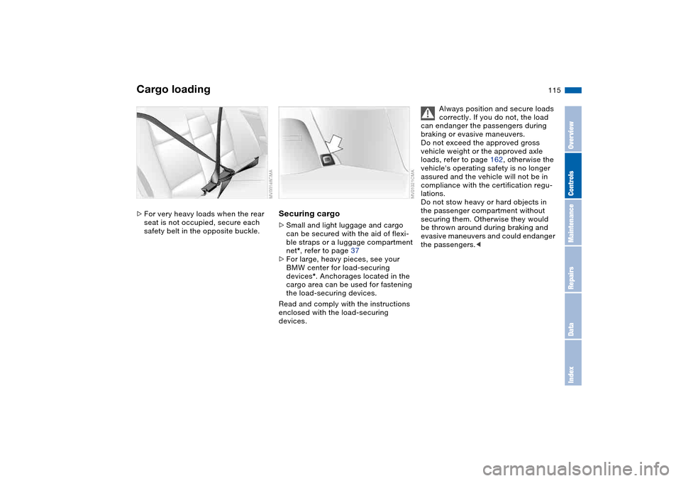
>For very heavy loads when the rear
seat is not occupied, secure each
safety belt in the opposite buckle.
Securing cargo>Small and light luggage and cargo
can be secured with the aid of flexi-
ble straps or a luggage compartment
net*, refer to page 37
>For large, heavy pieces, see your
BMW center for load-securing
devices*. Anchorages located in the
cargo area can be used for fastening
the load-securing devices.
Read and comply with the instructions
enclosed with the load-securing
devices.
Always position and secure loads
correctly. If you do not, the load
can endanger the passengers during
braking or evasive maneuvers.
Do not exceed the approved gross
vehicle weight or the approved axle
loads, refer to page 162, otherwise the
vehicle's operating safety is no longer
assured and the vehicle will not be in
compliance with the certification regu-
lations.
Do not stow heavy or hard objects in
the passenger compartment without
securing them. Otherwise they would
be thrown around during braking and
evasive maneuvers and could endanger
the passengers.<
Cargo loading
OverviewControlsMaintenanceRepairsDataIndex
Page 120 of 178
120Special operating instructions
Break-in proceduresTo ensure that your vehicle provides
maximum economy throughout a long
service life, we request that you
observe the following suggestions.Engine and differentialUp to 1,250 miles/2,000 km:
Constantly vary both vehicle and engine
speeds, remembering not to exceed
4,500 rpm or vehicle speeds of over
100 mph / 160 km/h:
Obey your local and state maximum
speed limits.
Do not use full throttle, and avoid
pressing the accelerator beyond the
kickdown point during these initial
miles.
You can then proceed to increase
engine or vehicle speeds once the ini-
tial 1,250 miles/2,000 km have elapsed.
You should also observe the same
break-in procedures if the engine or dif-
ferential should have to be replaced
later in the course of the vehicle's life.
TiresDue to technical factors associated
with their manufacture, tires do not
achieve their full traction potential until
an initial break-in period has elapsed.
Thus drive with extra care during the
initial 200 miles/300 km.
Obey your local and state maximum
speed limits.
When the vehicle is operated on
wet or slushy roads, a wedge of
water may form between the tire and
the road surface. This phenomenon is
referred to as hydroplaning, and can
lead to partial or complete loss of trac-
tion, as well as loss of vehicle control
and braking effectiveness. Reduce your
speed on wet roads.
achieve the optimal pad-surface and
wear patterns required for trouble-free
operation and long service life later on.
To break in the separate parking brake
drums, apply the parking brake lightly
when coasting to a standstill – at a traf-
fic signal, for instance – provided that
traffic conditions allow you to do so.
To avoid corrosion, repeat this proce-
dure from time to time.
The brake lamps do not come on
when the parking brake is set.
Vacuum for the brake system servo unit
on your BMW is available only when the
engine is running. When you move the
vehicle with the engine off – when tow-
ing, for example – substantially higher
levels of pedal force will be required to
brake the vehicle.
optimum efficiency. Remember to
engage the clutch carefully during this
initial period.
Page 125 of 178
125
Do not drive on a deflated – flat –
tire unless your vehicle is
equipped with Run Flat tires. A flat tire
greatly impairs steering and braking
response, and can lead to complete
loss of control over the vehicle.
Avoid overloading the vehicle so that
the permitted load on the tires is not
exceeded. Overloading can lead to
overheating and internal tire damage.
The ultimate result can assume the
form of a sudden air loss.
Unusual vibrations encountered during
normal vehicle operation can indicate a
damaged tire or some other vehicle
malfunction. This type of problem can
be caused by contact with curbs, etc.
This is also true for irregularities in the
vehicle's handling characteristics, such
as a pronounced tendency to pull to the
left or right. Should this occur, respond
by immediately reducing your speed.
Proceed carefully to the nearest BMW
center or professional tire center, or
have the vehicle towed in to have it, its
wheels or its tires inspected.
Tire damage, up to and including sud-
den and complete air loss, can endan-
ger the lives of both the vehicle occu-
pants and other road users.<
Tire replacementTo maintain good handling and vehicle
response, use only tires of a single
tread configuration from a single manu-
facturer.
Comply with the specified tire inflation
pressures — and be sure to have the
wheel and tire assembly balanced
every time you change a tire or wheel.DOT quality gradesTread wear
Traction AA A B C
Temperature A B C
All passenger car tires must con-
form to Federal Safety Require-
ments in addition to these grades.
when tested under controlled condi-
tions on a specified government test
course.
For example, a tire graded 150 would
wear one and one-half – 1
1/2 – times as
well on the government course as a tire
graded 100. The relative performance
of tires depends upon the actual condi-
tions of their use, however, and may
depart significantly from the norm due
to variations in driving habits, service
practices and differences in road char-
acteristics and climate.TractionThe traction grades, from highest to
lowest, are AA, A, B, and C.
Those grades represent the tire's ability
to stop on wet pavement as measured
under controlled conditions on speci-
fied government test surfaces of
asphalt and concrete. A tire marked C
may have poor traction performance.
The traction grade assigned to
this tire is based on straight-
ahead braking traction tests, and does
not include acceleration, cornering,
hydroplaning, or peak traction charac-
teristics.
tire's resistance to the generation of
heat and its ability to dissipate heat
when tested under controlled condi-
tions on a specified indoor laboratory
test wheel.
Tire condition
OverviewControlsMaintenanceRepairsDataIndex
Page 132 of 178
132
Washer fluidsHeadlamp* and windshield
washer systemCapacity approx.
5.6 US quarts/5.3 liters.
Fill with water and, if required, with a
washer antifreeze additive according to
manufacturer's recommendations.
We recommend that you mix the
washer fluid before adding it to
the reservoir.<
Rear window washer reservoirCapacity approx.
2.4 US quarts/2.3 liters.
Fill with water and, if required, with a
washer antifreeze additive according to
manufacturer's recommendations.
We recommend that you mix the
washer fluid before adding it to
the reservoir.<
Antifreeze agents for the washer
fluid are highly flammable. For this
reason, keep them away from sources
of flame and store them only in their
closed original containers. Store it inac-
cessible to children. Comply with the
instructions on the containers.<
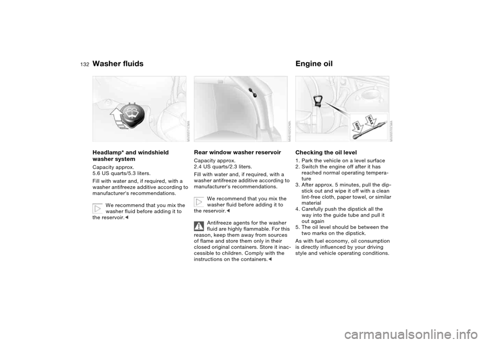
Engine oilChecking the oil level1. Park the vehicle on a level surface
2. Switch the engine off after it has
reached normal operating tempera-
ture
3. After approx. 5 minutes, pull the dip-
stick out and wipe it off with a clean
lint-free cloth, paper towel, or similar
material
4. Carefully push the dipstick all the
way into the guide tube and pull it
out again
5. The oil level should be between the
two marks on the dipstick.
As with fuel economy, oil consumption
is directly influenced by your driving
style and vehicle operating conditions.
Page 142 of 178
142Replacement procedures
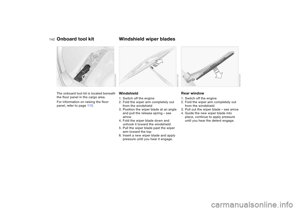
Onboard tool kitThe onboard tool kit is located beneath
the floor panel in the cargo area.
For information on raising the floor
panel, refer to page 113.
Windshield wiper bladesWindshield1. Switch off the engine
2. Fold the wiper arm completely out
from the windshield
3. Position the wiper blade at an angle
and pull the release spring – see
arrow
4. Fold the wiper blade down and
unhook it toward the windshield
5. Pull the wiper blade past the wiper
arm toward the top
6. Insert a new wiper blade and apply
pressure until you hear it engage.
Rear window1. Switch off the engine
2. Fold the wiper arm completely out
from the windshield
3. Pull out the wiper blade – see arrow
4. Guide the new wiper blade into
place, continue to apply pressure
until you hear the detent engage.
Page 144 of 178
144
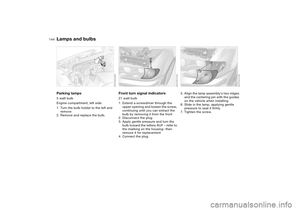
Parking lamps5 watt bulb
Engine compartment, left side:
1. Turn the bulb holder to the left and
remove
2. Remove and replace the bulb.
Front turn signal indicators21 watt bulb
1. Extend a screwdriver through the
upper opening and loosen the screw,
continuing until you can extract the
bulb by removing it from the front
2. Disconnect the plug
3. Apply gentle pressure and turn the
bulb toward the letters AUF – refer to
the marking on the housing– then
remove it for replacement
4. Connect the plug
5. Align the lamp assembly's two ridges
and the centering pin with the guides
on the vehicle when installing
6. Slide in the lamp, applying gentle
pressure to seat it firmly
7. Tighten the screw.
Lamps and bulbs
Page 145 of 178
145
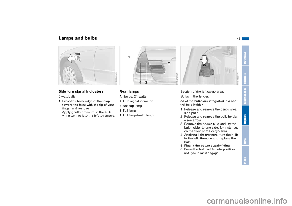
Side turn signal indicators5 watt bulb
1. Press the back edge of the lamp
toward the front with the tip of your
finger and remove
2. Apply gentle pressure to the bulb
while turning it to the left to remove.
Rear lampsAll bulbs: 21 watts
1Turn signal indicator
2Backup lamp
3Tail lamp
4Tail lamp/brake lamp
Section of the left cargo area:
Bulbs in the fender:
All of the bulbs are integrated in a cen-
tral bulb holder.
1. Release and remove the cargo area
side panel
2. Release and remove the bulb holder
– see arrow
3. Remove the power plug and lay the
bulb holder to one side, for instance,
on the floor of the cargo area
4. Applying light pressure, turn the bulb
to the left. Remove and replace the
bulb
5. Plug in the power supply fitting
6. Press the bulb holder into position
until you hear it engage.
Lamps and bulbs
OverviewControlsMaintenanceRepairsDataIndex