trunk BMW 328D SEDAN 2014 User Guide
[x] Cancel search | Manufacturer: BMW, Model Year: 2014, Model line: 328D SEDAN, Model: BMW 328D SEDAN 2014Pages: 242, PDF Size: 7.25 MB
Page 136 of 242
track line is continuously adjusted for the
steering wheel movement.
"Parking aid lines"
Turning circle and pathway lines are displayed.
System limits
Top View cannot be used in the following sit‐
uations:
▷With a door open.▷With the trunk lid open.▷With an exterior mirror folded in.▷In poor light.
A Check Control message is displayed in some
of these situations.
Parking assistant The concept
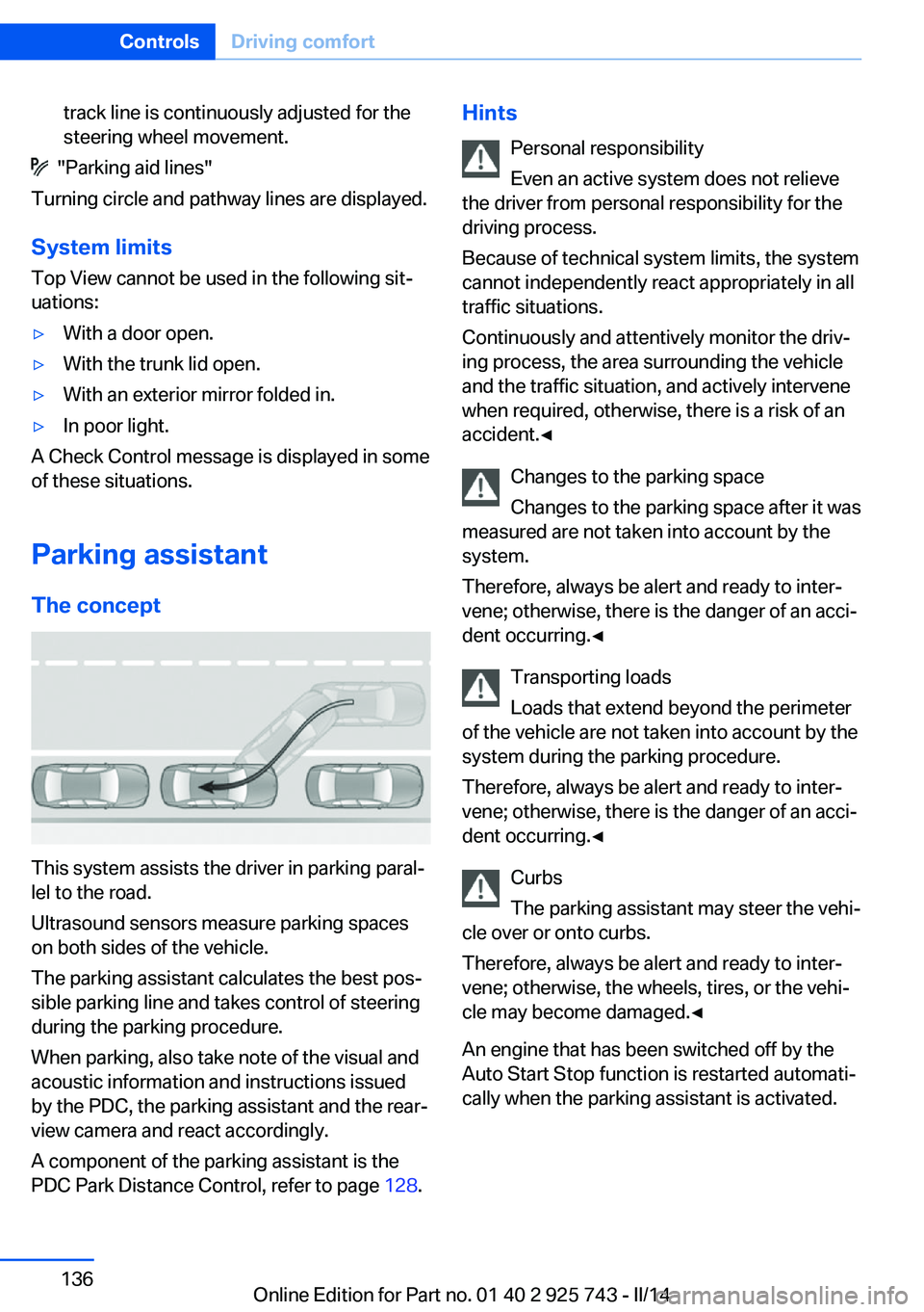
This system assists the driver in parking paral‐
lel to the road.
Ultrasound sensors measure parking spaces
on both sides of the vehicle.
The parking assistant calculates the best pos‐
sible parking line and takes control of steering
during the parking procedure.
When parking, also take note of the visual and
acoustic information and instructions issued
by the PDC, the parking assistant and the rear‐
view camera and react accordingly.
A component of the parking assistant is the
PDC Park Distance Control, refer to page 128.
Hints
Personal responsibility
Even an active system does not relieve
the driver from personal responsibility for the
driving process.
Because of technical system limits, the system
cannot independently react appropriately in all
traffic situations.
Continuously and attentively monitor the driv‐
ing process, the area surrounding the vehicle
and the traffic situation, and actively intervene
when required, otherwise, there is a risk of an
accident.◀
Changes to the parking space
Changes to the parking space after it was
measured are not taken into account by the system.
Therefore, always be alert and ready to inter‐
vene; otherwise, there is the danger of an acci‐
dent occurring.◀
Transporting loads
Loads that extend beyond the perimeter
of the vehicle are not taken into account by the
system during the parking procedure.
Therefore, always be alert and ready to inter‐
vene; otherwise, there is the danger of an acci‐
dent occurring.◀
Curbs
The parking assistant may steer the vehi‐
cle over or onto curbs.
Therefore, always be alert and ready to inter‐
vene; otherwise, the wheels, tires, or the vehi‐
cle may become damaged.◀
An engine that has been switched off by the
Auto Start Stop function is restarted automati‐
cally when the parking assistant is activated.Seite 136ControlsDriving comfort136
Online Edition for Part no. 01 40 2 925 743 - II/14
Page 137 of 242
Requirements
For measuring parking spaces▷Maximum speed while driving forward ap‐
prox. 22 mph/35 km/h.▷Maximum distance to row of parked vehi‐
cles: 5 ft/1.5 m.
Suitable parking space
▷Gap between two objects with a minimum
length of approx. 5 ft/1.5 m.▷Min. length of gap between two objects:
your vehicle's length plus approx.
4 ft/1.2 m.▷Minimum depth: approx. 5 ft/1.5 m.
For parking procedure
▷Doors and trunk lid closed.▷Parking brake released.▷When parking in parking spaces on the
driver's side, the corresponding turn signal
must be set where applicable.
At a glance
Button in the vehicle
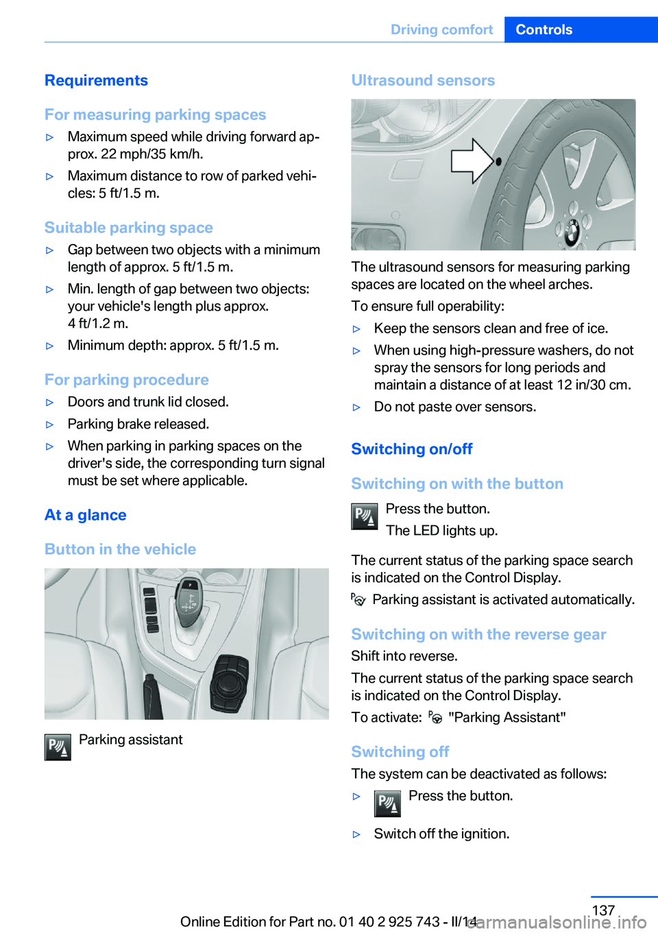
Parking assistant
Ultrasound sensors
The ultrasound sensors for measuring parking
spaces are located on the wheel arches.
To ensure full operability:
▷Keep the sensors clean and free of ice.▷When using high-pressure washers, do not
spray the sensors for long periods and
maintain a distance of at least 12 in/30 cm.▷Do not paste over sensors.
Switching on/off
Switching on with the button Press the button.
The LED lights up.
The current status of the parking space search
is indicated on the Control Display.
Parking assistant is activated automatically.
Switching on with the reverse gear
Shift into reverse.
The current status of the parking space search
is indicated on the Control Display.
To activate:
"Parking Assistant"
Switching off The system can be deactivated as follows:
▷Press the button.▷Switch off the ignition.Seite 137Driving comfortControls137
Online Edition for Part no. 01 40 2 925 743 - II/14
Page 157 of 242
LockingThe glove compartment can be locked with an
integrated key to separately secure the trunk
lid, refer to page 38, for example.
This prevents access to the glove compart‐
ment and to the cargo area.
After the glove compartment is locked, the re‐
mote control can be handed over, such as at a
hotel, without the integrated key.
Driver's side
Note Close the glove compartment again im‐
mediately
Close the glove compartment immediately af‐
ter use while driving; otherwise, injury may oc‐
cur during accidents.◀
Opening
Pull the handle.
ClosingFold cover closed.
Front storage compartment
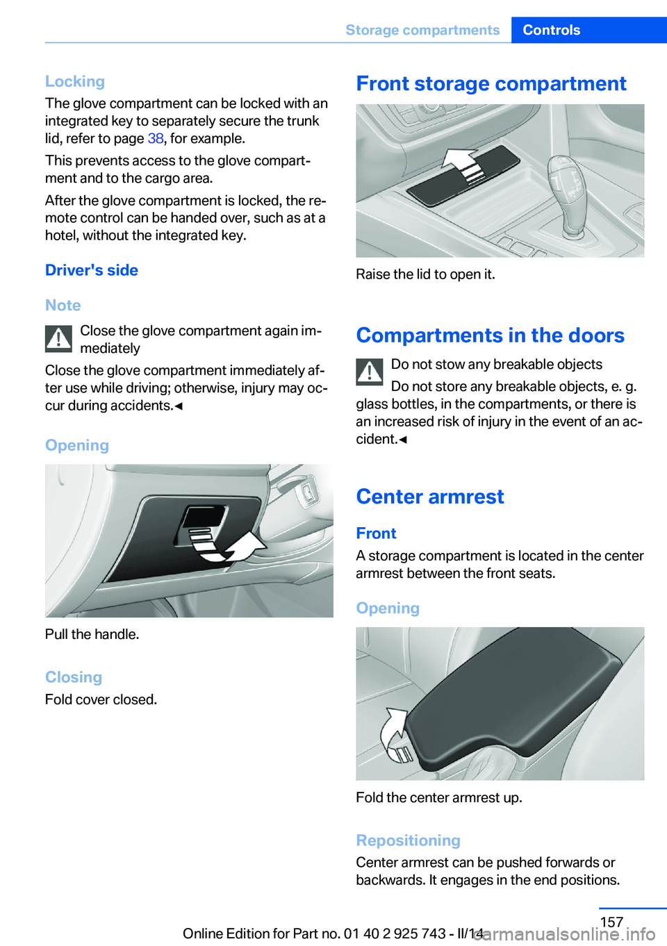
Raise the lid to open it.
Compartments in the doors Do not stow any breakable objects
Do not store any breakable objects, e. g.
glass bottles, in the compartments, or there is
an increased risk of injury in the event of an ac‐
cident.◀
Center armrest
Front A storage compartment is located in the center
armrest between the front seats.
Opening
Fold the center armrest up.
Repositioning
Center armrest can be pushed forwards or
backwards. It engages in the end positions.
Seite 157Storage compartmentsControls157
Online Edition for Part no. 01 40 2 925 743 - II/14
Page 159 of 242
No heavy objects
Do not hang heavy objects from the
hooks; otherwise, they may present a danger
to passengers during braking and evasive ma‐
neuvers.◀
Storage compartments in the
cargo area
Storage compartment A storage compartment is located on the left
side.
Located on the right side is a storage compart‐
ment for the onboard vehicle tool kit, refer to
page 204, and first aid kit, refer to page 216.
Net
Small objects can be stowed in the net on the
left side.
Hooks/multi-function hook
A multi-function hook is located on each side
of the cargo area.
The multi-function hooks can be loaded up to
a max. of 8.8 lbs/4 kg.
Light and suitable objects only
Only hang light bags or suitable objects
from the holders. Otherwise, there is a danger
of objects flying about during braking and eva‐
sive maneuvers.
Only transport heavy luggage in the trunk if it
has been appropriately secured.◀
Retaining strap
A retaining strap is available on the right side
trim for fastening small objects.
Lashing eyes in the cargo area To secure the cargo, refer to page 166, there
are four lashing eyes in the cargo area.
Floor net The floor net can also be used to Secure the
load, refer to page 166, and to store small
parts.
Storage compartment under cargo
floor panel
Maximum load
To avoid damage to the vehicle, do not
exceed a maximum permitted load of 44 lbs/
20 kg in the storage compartment under the
cargo floor panel.◀
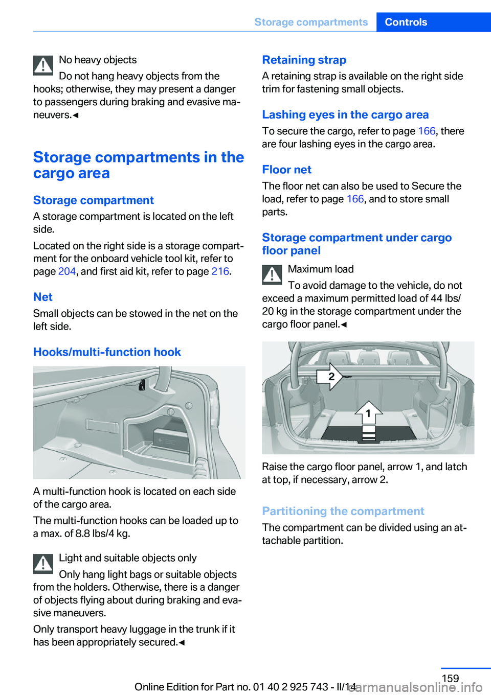
Raise the cargo floor panel, arrow 1, and latch
at top, if necessary, arrow 2.
Partitioning the compartment
The compartment can be divided using an at‐
tachable partition.
Seite 159Storage compartmentsControls159
Online Edition for Part no. 01 40 2 925 743 - II/14
Page 162 of 242
Things to remember when drivingVehicle equipment
All standard, country-specific and optional
equipment that is offered in the model series is
described in this chapter. Therefore, equip‐
ment is also described that is not available in a
vehicle, e. g., because of the selected optional
equipment or country variant. This also applies
for safety-related functions and systems.
Breaking-in period General information Moving parts need to be broken in to adjust to
each other.
The following instructions will help achieve a
long vehicle life and good economy.
Engine and differential Always obey the official speed limit.
Up to 1,200 miles/2,000 km
Do not exceed the maximum engine and road
speed:▷For gasoline engine 4,500 rpm and
100 mph/160 km/h.▷For diesel engine 3,500 rpm and
93 mph/150 km/h.
Avoid full load or kickdown under all circum‐
stances.
From 1,200 miles/2,000 km The engine and vehicle speed can gradually be
increased.
Tires
Due to technical factors associated with their
manufacture, tires do not achieve their full
traction potential until after an initial breaking-
in period.
Drive conservatively for the first
200 miles/300 km.
Brake system
Brakes require an initial break-in period of ap‐
prox. 300 miles/500 km to achieve optimized
contact and wear patterns between brake
discs and brake pads. Drive moderately during
this break-in period.
Clutch
The function of the clutch reaches its optimal
level only after a distance driven of approx.
300 miles/500 km. During this break-in period,
engage the clutch gently.
Following part replacement
The same breaking in procedures should be
observed if any of the components mentioned
above have to be renewed in the course of the
vehicle's operating life.
General driving notes
Closing the trunk lid Drive with the trunk lid closed
Only drive with the tailgate closed; other‐
wise, in the event of an accident or braking and
evasive maneuvers, passengers and other road
users may be injured, and the vehicle may be
damaged. In addition, exhaust fumes may en‐
ter the passenger compartment.◀
If driving with the tailgate open cannot be avoided:▷Close all windows and the glass sunroof.▷Greatly increase the blower speed.▷Drive moderately.Seite 162Driving tipsThings to remember when driving162
Online Edition for Part no. 01 40 2 925 743 - II/14
Page 165 of 242
LoadingVehicle equipment
All standard, country-specific and optional
equipment that is offered in the model series is
described in this chapter. Therefore, equip‐
ment is also described that is not available in a
vehicle, e. g., because of the selected optional
equipment or country variant. This also applies
for safety-related functions and systems.
Hints Overloading the vehicle
To avoid exceeding the approved carry‐
ing capacity of the tires, never overload the ve‐
hicle. Overloading can lead to overheating and
increases the rate at which damage develops
inside the tires. This could result in a sudden
loss of tire inflation pressure.◀
No fluids in the trunk
Make sure that fluids do not leak into the
trunk; otherwise, the vehicle may be dam‐
aged.◀
Heavy and hard objects
Do not stow any heavy and hard objects
in the passenger compartment without secur‐
ing them; otherwise, they may present a dan‐
ger to occupants, e.g., during braking and eva‐
sive maneuvers.◀
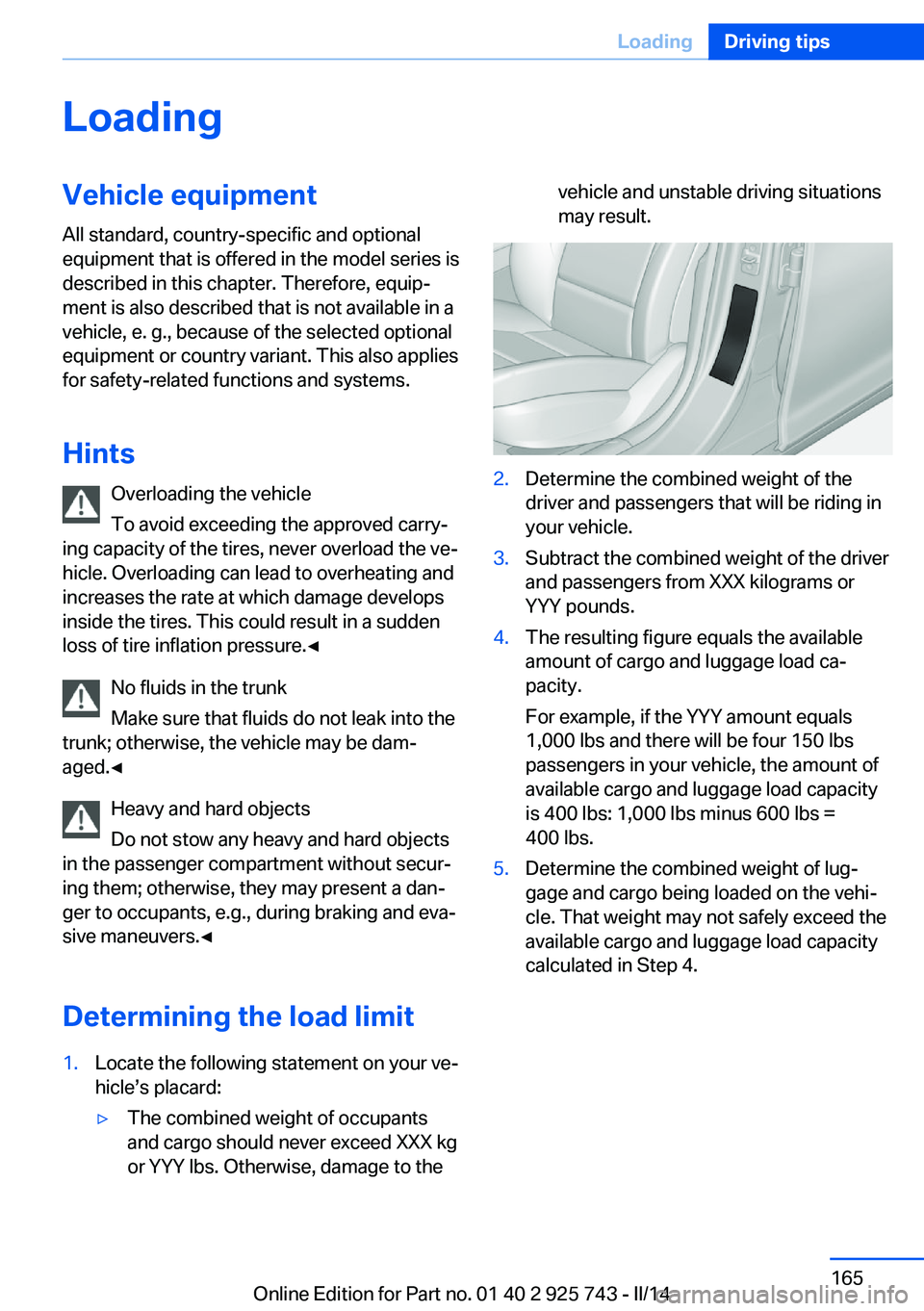
Determining the load limit1.Locate the following statement on your ve‐
hicle’s placard:▷The combined weight of occupants
and cargo should never exceed XXX kg
or YYY lbs. Otherwise, damage to thevehicle and unstable driving situations
may result.2.Determine the combined weight of the
driver and passengers that will be riding in
your vehicle.3.Subtract the combined weight of the driver
and passengers from XXX kilograms or
YYY pounds.4.The resulting figure equals the available
amount of cargo and luggage load ca‐
pacity.
For example, if the YYY amount equals
1,000 lbs and there will be four 150 lbs
passengers in your vehicle, the amount of
available cargo and luggage load capacity
is 400 lbs: 1,000 lbs minus 600 lbs =
400 lbs.5.Determine the combined weight of lug‐
gage and cargo being loaded on the vehi‐
cle. That weight may not safely exceed the
available cargo and luggage load capacity
calculated in Step 4.Seite 165LoadingDriving tips165
Online Edition for Part no. 01 40 2 925 743 - II/14
Page 167 of 242

Securing cargo
Stow and secure the cargo as described
above; otherwise it may present a danger to
the occupants, e.g., during braking and avoid‐
ance maneuvers.◀
Roof-mounted luggage rack
Note Roof racks are available as special accessories.
Securing
Follow the installation instructions of the roof
rack.
Roof drip rail with flaps
The anchorage points are located in the roof
drip rail above the doors.
Fold the cover outward.
Loading Be sure that adequate clearance is maintained
for tilting and opening the glass sunroof.
Because roof racks raise the vehicle's center
of gravity when loaded, they have a major ef‐
fect on vehicle handling and steering re‐
sponse.
Therefore, note the following when loading
and driving:
▷Do not exceed the approved roof/axle
loads and the approved gross vehicle
weight.▷Distribute the roof load uniformly.▷The roof load should not be too large in
area.▷Always place the heaviest pieces on the
bottom.▷Secure the roof luggage firmly, e.g., tie
with ratchet straps.▷Do not let objects project into the opening
path of the trunk lid.▷Drive cautiously and avoid sudden acceler‐
ation and braking maneuvers. Take corners
gently.Seite 167LoadingDriving tips167
Online Edition for Part no. 01 40 2 925 743 - II/14
Page 210 of 242
Tail lamps, bulb replacement
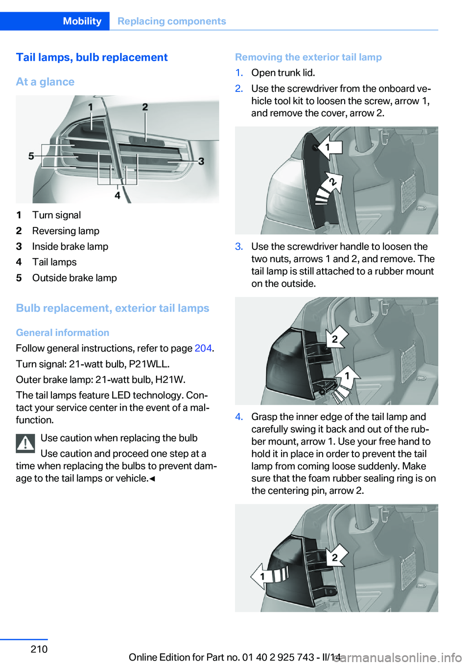
At a glance1Turn signal2Reversing lamp3Inside brake lamp4Tail lamps5Outside brake lamp
Bulb replacement, exterior tail lamps General information
Follow general instructions, refer to page 204.
Turn signal: 21-watt bulb, P21WLL.
Outer brake lamp: 21-watt bulb, H21W. The tail lamps feature LED technology. Con‐
tact your service center in the event of a mal‐
function.
Use caution when replacing the bulb
Use caution and proceed one step at a
time when replacing the bulbs to prevent dam‐
age to the tail lamps or vehicle.◀
Removing the exterior tail lamp1.Open trunk lid.2.Use the screwdriver from the onboard ve‐
hicle tool kit to loosen the screw, arrow 1,
and remove the cover, arrow 2.3.Use the screwdriver handle to loosen the
two nuts, arrows 1 and 2, and remove. The
tail lamp is still attached to a rubber mount
on the outside.4.Grasp the inner edge of the tail lamp and
carefully swing it back and out of the rub‐
ber mount, arrow 1. Use your free hand to
hold it in place in order to prevent the tail
lamp from coming loose suddenly. Make
sure that the foam rubber sealing ring is on
the centering pin, arrow 2.Seite 210MobilityReplacing components210
Online Edition for Part no. 01 40 2 925 743 - II/14
Page 211 of 242
5.Remove the connecting line from the clip
on the bulb holder.6.Release the catch at the top on the con‐
nector of the connecting line and remove
the connector from the bulb holder.
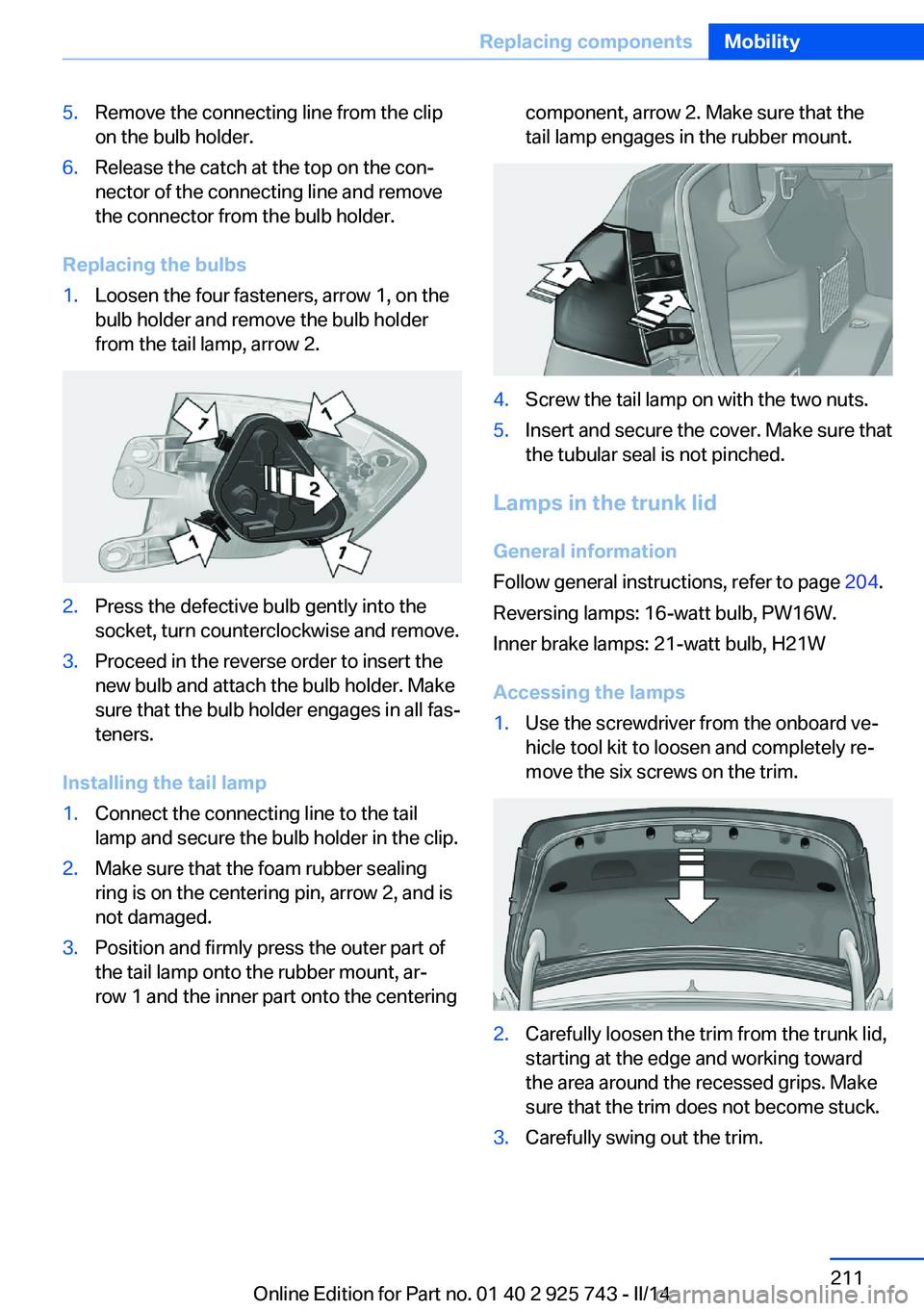
Replacing the bulbs
1.Loosen the four fasteners, arrow 1, on the
bulb holder and remove the bulb holder
from the tail lamp, arrow 2.2.Press the defective bulb gently into the
socket, turn counterclockwise and remove.3.Proceed in the reverse order to insert the
new bulb and attach the bulb holder. Make
sure that the bulb holder engages in all fas‐
teners.
Installing the tail lamp
1.Connect the connecting line to the tail
lamp and secure the bulb holder in the clip.2.Make sure that the foam rubber sealing
ring is on the centering pin, arrow 2, and is
not damaged.3.Position and firmly press the outer part of
the tail lamp onto the rubber mount, ar‐
row 1 and the inner part onto the centeringcomponent, arrow 2. Make sure that the
tail lamp engages in the rubber mount.4.Screw the tail lamp on with the two nuts.5.Insert and secure the cover. Make sure that
the tubular seal is not pinched.
Lamps in the trunk lid
General information
Follow general instructions, refer to page 204.
Reversing lamps: 16-watt bulb, PW16W.
Inner brake lamps: 21-watt bulb, H21W
Accessing the lamps
1.Use the screwdriver from the onboard ve‐
hicle tool kit to loosen and completely re‐
move the six screws on the trim.2.Carefully loosen the trim from the trunk lid,
starting at the edge and working toward
the area around the recessed grips. Make
sure that the trim does not become stuck.3.Carefully swing out the trim.Seite 211Replacing componentsMobility211
Online Edition for Part no. 01 40 2 925 743 - II/14
Page 212 of 242
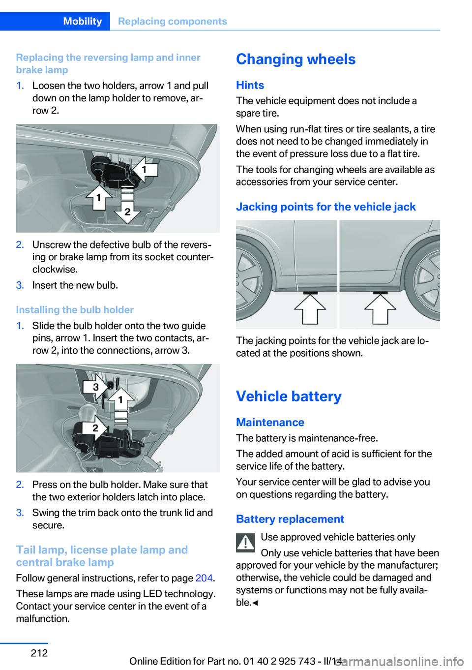
Replacing the reversing lamp and inner
brake lamp1.Loosen the two holders, arrow 1 and pull
down on the lamp holder to remove, ar‐
row 2.2.Unscrew the defective bulb of the revers‐
ing or brake lamp from its socket counter‐
clockwise.3.Insert the new bulb.
Installing the bulb holder
1.Slide the bulb holder onto the two guide
pins, arrow 1. Insert the two contacts, ar‐
row 2, into the connections, arrow 3.2.Press on the bulb holder. Make sure that
the two exterior holders latch into place.3.Swing the trim back onto the trunk lid and
secure.
Tail lamp, license plate lamp and
central brake lamp
Follow general instructions, refer to page 204.
These lamps are made using LED technology.
Contact your service center in the event of a
malfunction.
Changing wheels
Hints
The vehicle equipment does not include a
spare tire.
When using run-flat tires or tire sealants, a tire
does not need to be changed immediately in
the event of pressure loss due to a flat tire.
The tools for changing wheels are available as
accessories from your service center.
Jacking points for the vehicle jack
The jacking points for the vehicle jack are lo‐
cated at the positions shown.
Vehicle battery Maintenance
The battery is maintenance-free.
The added amount of acid is sufficient for the
service life of the battery.
Your service center will be glad to advise you
on questions regarding the battery.
Battery replacement Use approved vehicle batteries only
Only use vehicle batteries that have been
approved for your vehicle by the manufacturer;
otherwise, the vehicle could be damaged and
systems or functions may not be fully availa‐
ble.◀
Seite 212MobilityReplacing components212
Online Edition for Part no. 01 40 2 925 743 - II/14