traction BMW 328i 1992 E36 User Guide
[x] Cancel search | Manufacturer: BMW, Model Year: 1992, Model line: 328i, Model: BMW 328i 1992 E36Pages: 759
Page 187 of 759
2
.
Remove
fuel
tank
filler
cap
.
3
.
Remove
rearseat
cushion
and
pull
back
insulation
mats
to
expose
fuel
tank
access
covers
.
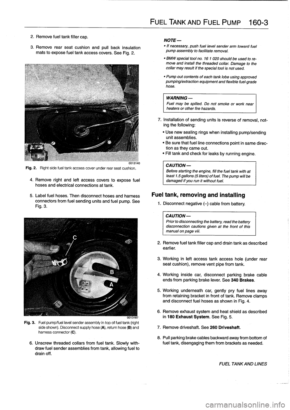
See
Fig
.
2
.
uui3140
Fig
.
2
.
Right
side
fuel
tank
access
cover
under
rear
seat
cushion
.
4
.
Remove
right
and
left
access
covers
to
expose
fuel
hoses
and
electrical
connections
at
tank
.
5
.
Label
fuel
hoses
.
Then
disconnect
hoses
and
harness
connectors
from
fuel
sending
units
and
fuel
pump
.
See
Fig
.
3
.
FUELTANK
AND
FUEL
PUMP
160-
3
NOTE-
"
If
necessary,
push
fuel
level
sender
arm
toward
fuel
pump
assembly
to
facilitate
removal
.
"
BMW
special
tool
no
.
16
1
020
should
beused
tore-
move
and
install
the
threaded
collar
.
Damage
to
thecollar
may
result
if
the
special
tool
is
not
used
.
"
Pump
out
contents
of
each
tanklobe
using
approved
pumpinglextraction
equipment
and
flexible
fuel-grade
hose
.
WARNING
-
Fuel
may
be
spilled
.
Do
not
smoke
or
work
near
heaters
or
other
fire
hazards
.
7
.
Installation
of
sending
units
is
reverse
of
removal,
not-
ing
the
following
:
"
Use
new
sealing
rings
when
installing
pump/sending
unit
assemblies
.
"
Be
sure
that
fuel
line
connections
point
in
same
direc-tion
as
they
carne
out
.
"
Fill
tank
and
check
for
leaks
by
running
engine
.
CA
UTION-
Before
starting
the
engine,
fill
the
fuel
tank
with
at
least
1.5
gallons
(5liters)
of
fuel
.
The
pump
will
be
damaged
if
you
run
it
without
fuel
.
Fuel
tank,
removing
and
installing
1.
Disconnect
negative
(-)cablefrom
battery
:
CAUTION-
Prior
to
disconnectiog
the
battery,
read
the
battery
disconnection
cautions
given
at
the
front
of
this
manual
onpage
viii
.
2
.
Remove
fuel
tank
filler
capand
drain
tank
as
described
earlier
.
3
.
Working
in
left
access
tank
access
hole
(under
rear
seat
cushion),
remove
vent
pipe
fromtank
.
4
.
Working
inside
car,
disconnectparking
brake
cable
ends
from
parking
brake
lever
.
See
340
Brakes
.
5
.
Working
underneath
car,
gently
pry
fuel
lines
away
from
retaining
bracket
in
front
of
tank
.
Remove
clamps
and
disconnect
fuel
hoses
as
shown
in
Fig
.
4
.
6
.
Remove
exhaust
system
and
heat
shield
as
described
ooisiai
in
180
Exhaust
System
.
See
Fig
.
5
.
Fig
.
3
.
Fuel
pump/fuel
level
sender
assembly
in
top
offuel
tank
(right
side
shown)
.
Disconnect
supply
hose
(A),
return
hose
(B)
and
7
.
Remove
driveshaft
.
See
260
Driveshaft
.
harness
connector
(C)
.
8
.
Pull
parking
brake
cables
backward
away
from
bottom
of
6
.
Unscrew
threaded
collars
from
fuel
tank
.
Slowly
with-
fuel
tank,
disengaging
them
from
brackets
as
needed
.
draw
fuel
sender
assemblies
from
tank,allowing
fuel
to
drain
off
.
FUEL
TANKAND
LINES
Page 223 of 759
Selector
shaft
seal,
replacing
(transmission
instalied)
1
.
Raise
and
safely
support
vehicle
to
access
drain
plug
.
2
.
Support
transmission
with
transmission
jack
.
3
.
Remove
driveshaft
.
See
260
Driveshaft
.
4
.
Remove
transmission
crossmember
and
tilt
down
rear
of
transmission
.
CA
UTION--
Tilting
the
engine
to
lower
the
transmission
can
lead
to
damage
to
various
cgmponents
due
to
lack
of
clearance
.
-On
cars
with
AST
(traction
control)
remove
throt-
tle
body
before
tiltlng
engine
.
-Remove
brake
fluid
reservoir
lf
necessary
.
Locking
pin
á
Locking
clip
8
.
Reinstall
shift
linkage
to
selectorshaft
.
7
.
Coat
new
seal
with
transmission
fluid
.
Drive
new
seal
in
flush
with
housing
.
Use
BMW
special
seal
installation
tool
no
.
23
2
260
orequivalent
and
a
soft-faced
(plastic)
hammer
.
See
Fig
.
4
.
9
.
Fiaise
transmission
and
reinstall
crossmember
.
MANUAL
TRANSMISSION
230-
3
Seal
Selector
_
shaft
5
.
Working
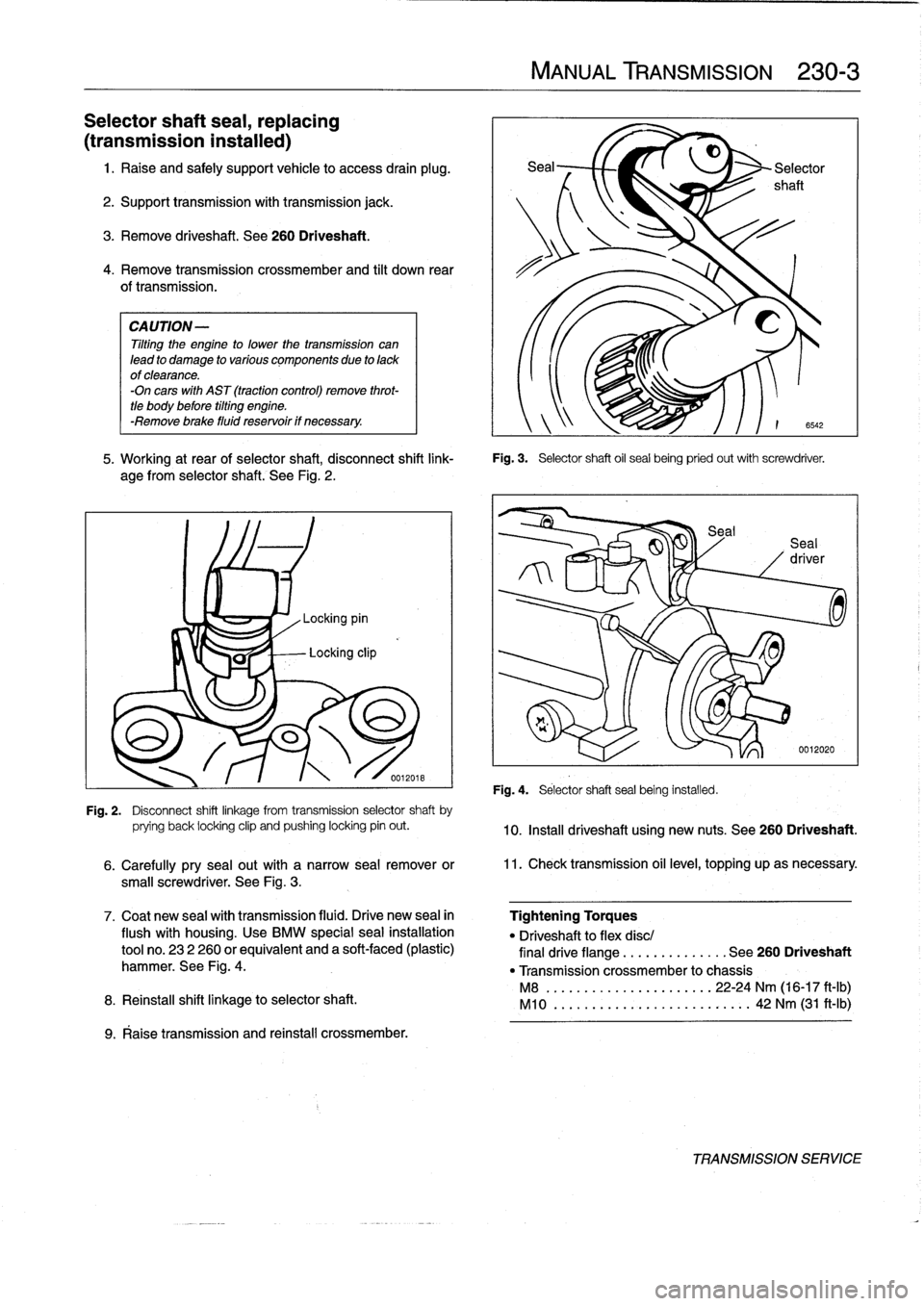
at
rear
of
selector
shaft,
disconnect
shift
link-
Fig
.
3
.
Selector
shaft
oil
sea¡
being
pried
out
with
screwdriver
.
age
from
selectorshaft
.
See
Fig
.
2
.
Fig
.
4
.
Selector
shaftseal
being
installed
.
6542
0012020
Fig
.
2
.
Disconnect
shift
linkage
from
transmission
selector
shaft
by
prying
back
locking
clip
and
pushing
locking
pin
out
.
10
.
Install
driveshaft
using
new
nuts
.
See260
Driveshaft
.
6
.
Carefully
pry
sea¡
out
with
a
narrow
seal
remover
or
11
.
Check
transmission
oil
level,
topping
upas
necessary
.
small
screwdriver
.
See
Fig
.
3
.
Tightening
Torques
"
Driveshaftto
flex
disc/
final
drive
flange
..............
See
260
Driveshaft
"
Transmission
crossmember
to
chassis
M8
........
..
.
...
........
22-24
Nm
(16-17
ft-1b)
M10
........
.
.
...
...
.
.........
42
Nm
(31
ft-Ib)
TRANSMISSIONSERVICE
Page 224 of 759
230-
4
MANUAL
TRANSMISSION
Output
shaft
sea¡,
replacing
(transmission
installed)
1
.
Raise
and
safely
support
vehicle
.
Support
transmission
with
transmission
jack
.
WARNING
-
"
When
raising
thecar
using
a
floor
jack
or
a
hy-
draulic
lift,
carefully
position
the
jack
pad
to
pre-vent
damaging
the
car
body
.
A
suitable
liner
(wood,
rubber,
etc
.)
should
be
placed
between
the
jack
and
the
car
to
prevent
body
damage
.
"
Watch
the
jack
closely
.
Make
sure
it
stays
stable
and
does
not
shift
or
tilt
.
As
the
car
is
raised,
the
car
may
roll
slightly
and
the
jack
may
shift
.
2
.
Remove
driveshaft
.
See
260
Driveshaft
.
3
.
Remove
transmission
crossmember
and
lower
trans-
mission
at
rear
.
CAUTION-
Tilting
the
engine
to
lower
thetransmissíon
can
lead
to
damage
to
various
componente
due
to
lackof
clearance
.
-On
cars
with
AST
(traction
control)
remove
throt-
tle
body
before
tilting
engine
.
-Remove
brake
fluid
reservoir
if
necessary
.
4
.
Bend
back
and
remove
collar
nut
lockplate
.
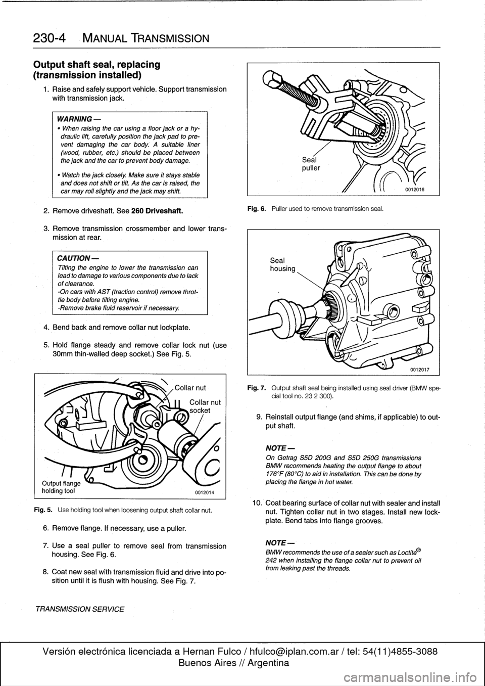
5
.
Hold
flange
steady
andremove
collar
lock
nut
(use
30mm
thin-walled
deep
socket
.)
See
Fig
.
5
.
Fig
.
5
.
Use
holding
tool
when
loosening
output
shaft
collar
nut
.
6
.
Remove
flange
.
If
necessary,
use
a
puller
.
7
.
Use
a
sea¡
puller
to
remove
seal
from
transmission
housing
.
See
Fig
.
6
.
8
.
Coat
new
sea¡
wíth
transmission
fluid
and
drive
into
po-
sition
until
it
is
flush
with
housing
.
See
Fig
.
7
.
TRANSMISSIONSERVICE
Fig
.
6
.
Puller
used
to
remove
transmission
seal
.
Fig
.
7
.
Output
shaftseal
being
installed
using
seal
driver
(BMW
spe-
cial
tool
no
.
232
300)
.
9
.
Reinstall
output
flange
(and
shims,
if
applicable)
to
out-
put
shaft
.
NOTE-
On
Getrag
S5D200G
and
S5D
250G
transmissions
BMW
recommends
heating
theoutputflange
to
about
176°F
(80°C)
to
aid
in
installation
.
This
canbe
done
by
placing
the
flange
in
hot
water
.
10
.
Coat
bearingsurface
ofcollar
nut
withsealer
and
install
nut
.
Tighten
collar
nut
in
two
stages
.
Insta¡¡
new
lock-
plate
.
Bend
tabs
into
flange
grooves
.
NOTE-
BMW
recommends
the
use
of
a
sealer
such
as
Loctite
®
242
when
installing
the
flange
collar
nut
to
prevent
oil
from
leaking
past
the
threads
.
Page 249 of 759
SUSPENSION,
STEERING
ANDBRAKES-GENERAL
300-1
300
Suspension,
Steering
and
Brakes-General
GENERAL
.....
.
....
.
.....
.
.
.
........
.300-1
M3
SUSPENSION
AND
BRAKES
.......
.
...
300-7
Front
Suspension
..........
.
.
.
...
.
.....
300-1
Steering
...
.
.
.
.
.
....
.
.
.
...
.
.
.
...
.
...
.
.
300-2
SUSPENSION
AND
STEERING
Rear
Suspension
....
.
.
.
...
.
.
.
...
.
.....
300-2
TROUBLESHOOTING
..
.
.
.
.............
300-7
Brakes
.
.
.
.
.
.
.
.
....
.
...........
.
.
.
.
.
.
300-2
Tires
and
wheeis
.
................
.
.
.
.
.
.
300-2
TABLE
a
.
AST
Indicator
Lamp
Function
..
..
.
..
.
.........
300-5
INTEGRATED
SYSTEMS
.........
.
.
.
.
.
.
300-2
b
.
Suspension
and
Steering
Troubleshooting
......
.300-8
Antilock
Brake
System
(ABS)
.......
.
.
.
.
.
.
300-2
Al¡
Season
Traction
(AST)
.........
.
.
.
.
.
.
300-4
GENERAL
Front
Suspension
This
section
covers
general
information
for
front
and
rear
The
lower
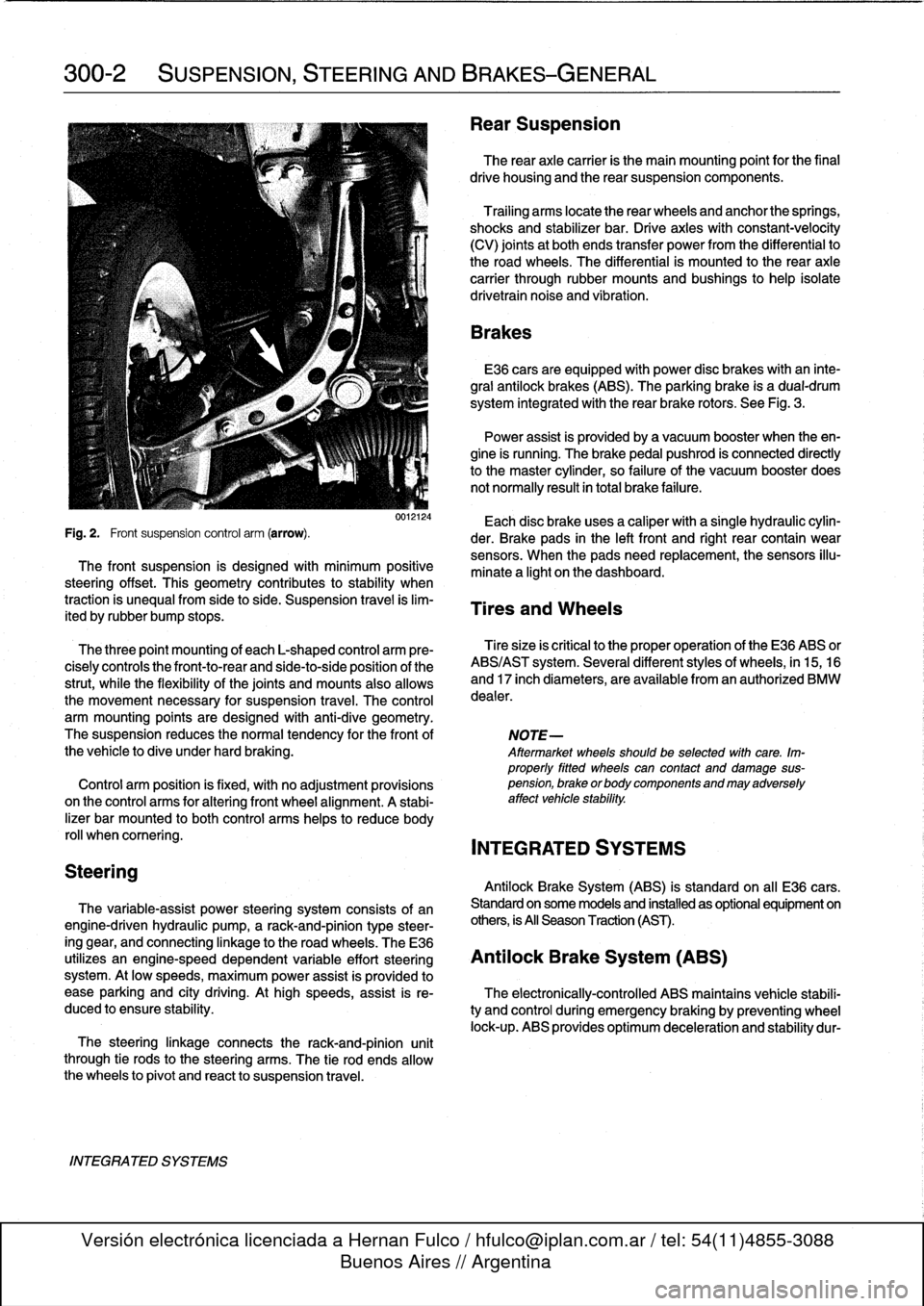
control
arms
connect
the
front
suspension
struts
suspension,
the
steering
system,
and
the
brakíng
and
traction
to
mounting
points
on
the
subframe
crossmember
and
the
control
systems
.
body
.
See
Fig
.
2
.
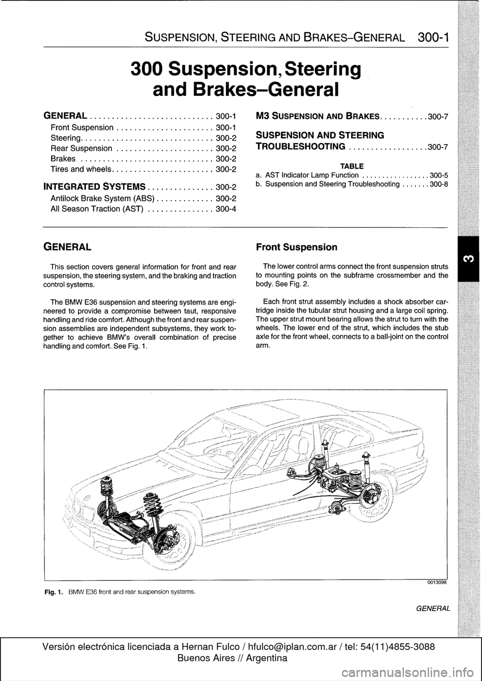
The
BMW
E36
suspension
and
steering
systems
are
engi-
neered
to
provide
a
compromise
between
taut,
responsive
handling
and
ride
comfort
.
Although
the
front
and
rear
suspen-
sion
assemblies
are
independent
subsystems,
they
work
to-
gether
to
achieve
BMW's
overall
combination
of
precise
handling
and
comfort
.
See
Fig
.
1
.
Fig
.
1
.
BMW
E36
front
and
rear
suspension
systems
.
Each
front
strut
assembly
includes
a
shock
absorber
car-
tridgeinside
the
tubular
strut
housing
and
a
large
coil
spring
.
The
upper
strut
mount
bearing
allows
the
strutto
turnwith
the
wheels
.
The
lower
end
of
the
strut,
which
includes
the
stub
axle
for
the
front
wheel,
connects
to
a
ball-joint
on
the
control
arm
.
0013098
GENERAL
Page 250 of 759
300-2
SUSPENSION,
STEERING
AND
BRAKES-GENERAL
Steering
INTEGRATED
SYSTEMS
The
steering
linkage
connects
the
rack-and-pinion
unit
through
tie
rodsto
the
steering
arms
.
The
tie
rod
ends
allow
the
wheels
to
pivot
and
react
to
suspension
travel
.
Rear
Suspension
The
rear
axle
carrier
is
the
main
mounting
point
for
the
final
drive
housing
and
the
rear
suspension
components
.
Trailing
arms
locatethe
rear
wheels
and
anchorthe
springs,
shocks
and
stabilizer
bar
.
Driveaxies
with
constant-velocity
(CV)
joints
at
both
ends
transfer
power
from
the
differential
to
the
road
wheels
.
The
differential
is
mounted
to
the
rearaxle
carrier
through
rubber
mountsand
bushings
to
hele
isolate
drivetrain
noise
and
vibration
.
Brakes
E36
cars
areequipped
with
power
disc
brakes
with
an
inte-
gral
antilock
brakes
(ABS)
.
The
parking
brake
is
a
dual-drum
system
integrated
with
the
rear
brake
rotors
.
See
Fig
.
3
.
Power
assist
is
provided
by
a
vacuum
booster
when
the
en-
gine
is
running
.
The
brakepedal
pushrod
is
connected
directly
to
the
master
cylinder,
so
failure
of
the
vacuum
booster
does
not
normally
result
in
total
brake
failure
.
0012124
Each
disc
brakeuses
a
caliper
with
a
single
hydraulic
cylin-
Fig
.
2
.
Front
suspension
control
arm
(arrow)
.
der
.
Brake
pads
in
the
left
front
and
right
rear
contain
wear
sensors
.
When
the
padsneed
replacement,the
sensors
illu-
The
front
suspension
is
designed
with
minimum
positive
minate
a
light
on
the
dashboard
.
steering
offset
.
This
geometry
contributes
to
stability
when
traction
is
unequalfrom
side
to
side
.
Suspension
travel
is
lim-
Tires
and
Wheels
ited
by
rubber
bump
stops
.
The
three
point
mounting
of
each
L-shaped
control
arm
ere-
Tiresize
is
critica¡
to
the
proper
operatíon
of
the
E36
ABS
or
cisely
controls
the
front-to-rear
and
side-to-side
position
of
the
ABS/AST
system
.
Severa¡
different
styles
of
wheels,
in
15,16
strut,
while
the
flexibility
of
the
joints
and
mounts
alsoallows
and
17
inch
diameters,
are
available
from
an
authorized
BMW
the
movement
necessary
for
suspension
travel
.
The
control
dealer
.
arm
mounting
points
are
designed
with
anti-dive
geometry
.
The
suspension
reduces
the
normaltendency
for
the
front
of
NOTE-
the
vehicle
to
dive
under
hard
braking
.
Aftermarket
wheelsshould
be
selected
wlth
care
.
Im-
properly
fitted
wheels
can
contact
anddamage
sus
Control
arm
position
is
fixed,
with
no
adjustment
provisions
pension,
brakeorbodycomponentsandmayadversely
on
the
control
arms
for
alter¡ng
front
wheel
al
ignment
.
A
stabi-
affect
vehicle
stability
.
lizer
bar
mounted
to
both
control
arms
heles
to
reduce
body
rol¡
whencomering
.
INTEGRATED
SYSTEMS
Antilock
Brake
System
(ABS)
is
standard
on
all
E36
cars
.
The
variable-assist
power
steering
system
consists
of
an
Standard
on
some
models
and
installed
as
optional
equipment
on
engine-driven
hydraulic
pump,
a
rack-and-pinion
type
steer-
others,
is
All
Season
Traction
(AST)
.
ing
gear,
and
connecting
linkage
to
the
road
wheels
.
TheE36
utilizes
an
engine-speed
dependent
variable
effort
steering
Antilock
Brake
System
(ABS)
system
.
At
low
speeds,
maximum
power
assist
is
provided
to
ease
parking
and
city
driving
.
Athigh
speeds,
assist
is
re-
The
electronically-controlled
ABS
maintains
vehícle
stabili
duced
to
ensure
stability
.
ty
and
control
during
emergency
braking
by
preventing
wheel
lock-up
.
ABS
provides
optimum
deceleration
and
stability
dur-
Page 252 of 759
300-4
SUSPENSION,
STEERING
AND
BRAKES-GENERAL
Three-channel
ABS
ís
used
on
al[
E36
cars
equipped
with
Al¡
Season
Traction
(AST)
standard
ABS
.
Each
front
wheelhas
a
separate
solenoid
valve
to
modulate
hydraulic
pressure
to
that
brake
caliper
.
The
traction
control
system
works
in
conjunction
with
ABS
The
rear
wheels
are
modulated
asa
pair,
controlled
by
a
sin-
and
the
engine
management
system
to
enhance
vehicle
con
gle
solenoid
valve
.
trol
.
The
main
function
of
the
AST
system
is
to
maintain
the
rolling
contact
between
the
tires
and
the
road
surface
under
al¡
driving
E36
cars
equipped
with
ABS/AST
utilize
a
four
channel
sys-
conditions
.
This
is
achieved
through
exact
application
and
tem,
which
functionsexactly
as
the
three
channelsystem
management
of
braking
and
drivetrain
forces
.
above,except
that
the
rear
wheels
are
modulated
individually
.
IDLE
SPEED
CONTROL
VALVE
HROTTLE
PLATE
6
.
Í
III
i
ADS
ACTU
AT
OR
THROTTLE
PLATE
POSITION
SENSOR
DME
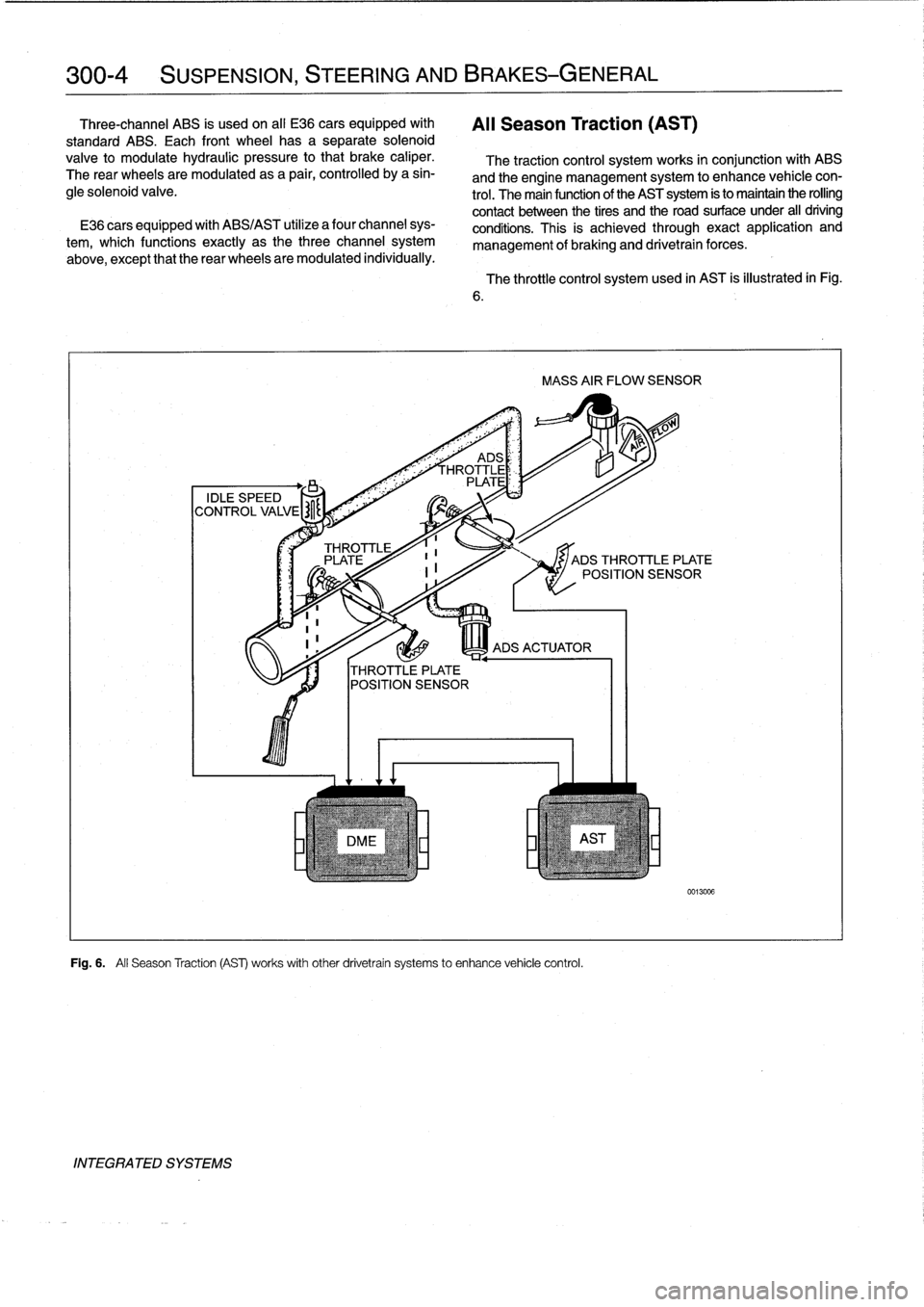
Fig
.
6
.
All
Season
Traction
(AS)
works
withother
drivetrain
systems
to
enhance
vehicle
control
.
INTEGRATED
SYSTEMS
The
throttle
control
system
used
in
AST
is
illustrated
in
Fig
.
MASS
AIR
FLOW
SENSOR
JADS
THROTTLE
PLATE
POSITION
SENSOR
0013006
Page 253 of 759
NOTE-
The
traction
control
system
referred
to
as
AST
(all
sea-
son
traction)
may
also
be
referred
to
as
ASC
(Automat-
ic
Stability
Control)
and
ASC+T
(Automatic
Stability
Control+Traction)
.
The
AST
system
improves
traction
by
electronically
apply-
ing
the
rear
brakes
when
therear
drive
wheels
are
spinning
at
a
faster
rate
than
the
front
wheels
.
The
combined
ABS/AST
control
module,
operating
through
the
ABS
hydraulic
control
unit,
modulates
braking
force
at
therear
wheels
.
In
addition,
AST
uses
retarded
ignition
timing
and
an
auxil-iary
engine
throttle
plate
to
reduceengine
torque
and
maintain
vehicle
stability
.
The
auxiliary
throttle
plate
is
held
open
by
spring
pressure
.
The
AST
system
actívates
the
auxiliary
throttie
position
motor
(ADS)
to
cose
the
AST
throttle
as
needed
.
This
reduces
the
volume
of
engine
intake
air
.
Due
to
the
throttle
closing
very
rapidly
during
AST
operationthe
driver
cannot
increase
theengine
power
output
regardless
of
how
far
theaccelerator
pedal
is
pushed
to
the
floor
.
The
auxiliary
throttle
plate
is
placed
ahead
of
the
conven-
tional
throttle
plate
in
the
throttle
body
.
Traction
control
also
comes
into
operationduringdecelera-
tion
.
Decelerating
on
snowy
or
icy
road
surfaces
can
lead
to
rear
wheel
slip
.
If
a
rear
wheel
startsto
drag
or
lock
up
when
the
throttle
is
closed
rapidly
orduringdownshifting,the
AST
system
can
limit
the
problem
by
advancing
the
ignition
timing
.
A
switch
on
the
center
console
is
used
to
togglethe
AST
on
or
off
.
The
AST
system
is
designed
to
be
maintenance
free
.
There
are
no
adjustments
that
can
be
made
.
Repair
and
trouble-
shooting
of
the
AST
system
requires
special
test
equipment
andknowledgeand
should
be
performed
only
by
an
autho-
rized
BMW
dealer
.
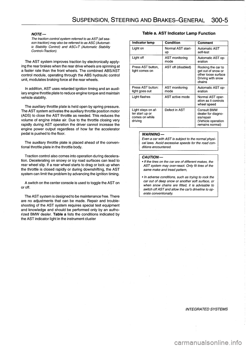
Table
a
lists
theconditions
indicated
by
the
AST
indicator
light
in
the
instrument
cluster
SUSPENSION,
STEERING
AND
BRAKES-GENERAL
300-5
Tablea
.
AST
Indicator
Lamp
Function
Indicator
lamp
1
Condition
1
Comment
Light
on
Normal
AST
start-
Automatic
AST
up
self-test
Light
off
AST
monitoring
Automatic
AST
op-
mode
eration
Press
AST
button,
AST
off
(disabled)
Rocking
the
car
tolight
comes
on
getout
of
snow
or
other
loose
surface
Driving
with
snow
chains
Press
AST
button
:
AST
monitoring
Automatic
AST
op-
light
goes
out
I
mode
eration
Light
flashes
AST
active
mode
I
Normal
AST
oper-
ation
as
it
controls
wheel
speed
Light
stays
on
af-
Defect
in
AST
Consult
BMW
ter
start
up
or
dealer
for
diagno-
comes
on
while
sis/repair
driving
(Vehicle
operation
remains
normal)
WARNING
-
Even
a
car
with
AST
is
subject
to
the
normal
physi-
cal
laws
.
Avoid
excessive
speeds
for
the
road
con-
ditions
encountered
.
CAUTION-
"
If
the
tires
on
the
carare
of
different
makes,
the
AST
system
may
over-react
.
Only
fit
tires
of
the
same
make
and
tread
pattem,
"In
adverse
conditions,
such
as
trying
to
rock
the
car
outof
deep
snow
or
another
soft
surface,
or
when
snow
chainsare
fitted,
it
is
advisable
to
switch
off
AST
and
allow
the
cars
driveline
to
op-
erate
conventionally
.
INTEGRATED
SYSTEMS
Page 254 of 759
300-6
SUSPENSION,
STEERING
AND
BRAKES-GENERAL
BATTE
RY
KL
30
ECM
MAIN
C~
RELAY
KL
15
DSC
SWITCH
LF1
;1~lZZ~
nSLn
l'
z
sJ
WHEEL
RF
c_
.
LR
r_
.
>
RR
ELECTRONIC
BRAKE
LIGHT
SWITCH
SPEED
SENSORS
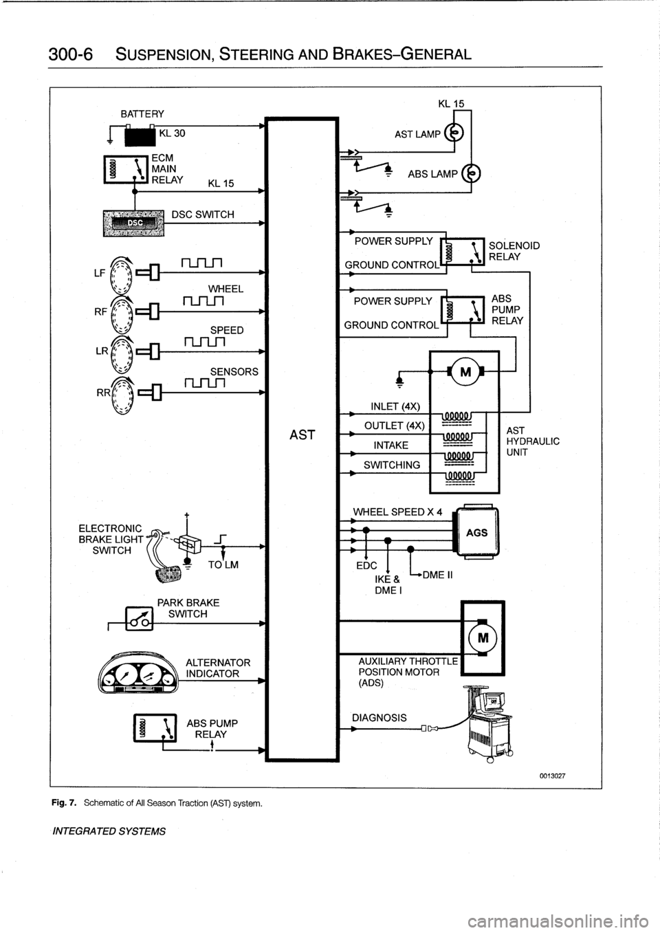
Fig
.
7
.
Schematic
of
AII
Season
Traction
(AST)
system
.
INTEGRATED
SYSTEMS
EDC
POWER
SUPPLY
SOLENOID
RELAY
GROUND
CONTROL
POWER
SUPPLY
I'
1
ABS
PUMP
GROUND
CONTROLÍ
F
f
iJ
RELAY
INLET
(4X)
wxxuw
OUTLET
(4X)
-=-=--
AST
AST
INTAKE
IHYDRAULIC
-
=-
SWITCHING
=---
!
99001
!J
WHEEL
SPEED
X
4
DME
II
000001
-
f
1
UNIT
AGS
IKE
&
DMEI
PARK
BREVE
771
SWITCH
M
ALTERNATOR
AUXILIARY
THROTTLE
r
`
INDICATOR
POSITION
MOTOR
(ADS)
ABSPUMP
DIAGNOSIS
RELAY
lu~~~b
0013027
Page 292 of 759
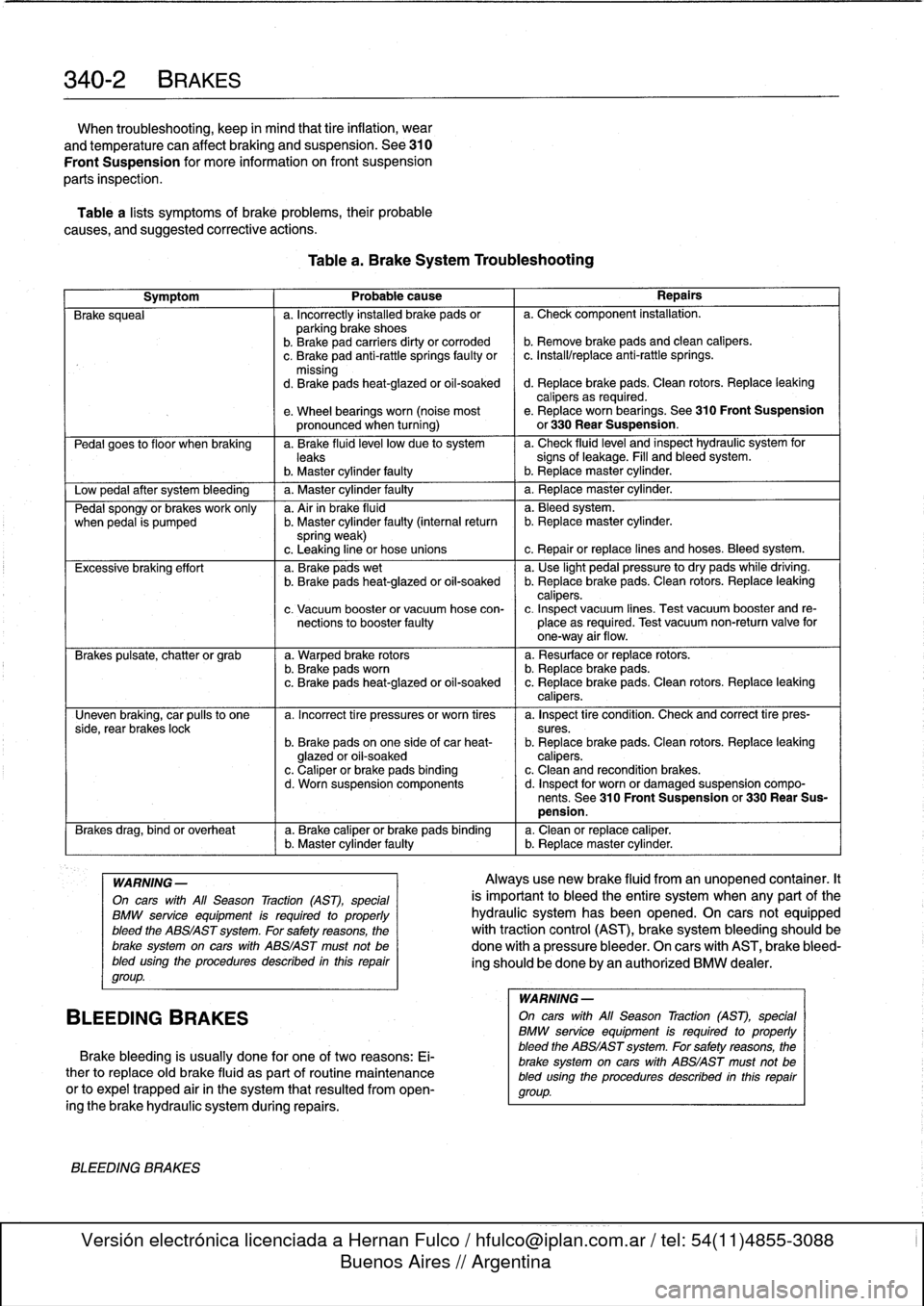
340-2
BRAKES
When
troubleshooting,
keep
in
mind
that
tire
inflation,
wear
and
temperature
can
affect
braking
and
suspension
.
See310
Front
Suspension
for
more
information
on
front
suspension
parts
inspection
.
Table
a
lists
symptoms
of
brake
problems,
their
probable
causes,
and
suggested
corrective
actions
.
Table
a
.
Brake
System
Troubleshooting
Symptom
1
Probable
cause
1
Repairs
Brake
squeal
a
.
Incorrectly
installed
brake
pads
or
a
.
Check
component
installation
.
parking
brake
shoes
b
.
Brakepad
carriers
dirty
or
corroded
b
.
Remove
brake
pads
and
clean
calipers
.
c
.
Brake
pad
anti-rattle
springs
faulty
or
c
.
Install/replace
anti-rattle
springs
.
missing
d
.
Brakepads
heat-glazed
or
oil-soaked
d
.
Replace
brake
pads
.
Clean
rotors
.
Replace
leaking
calipers
as
required
.
e
.
Wheel
bearings
worn
(noise
most
e
.
Replace
worn
bearings
.
See310
Front
Suspension
pronounced
when
turning)
or
330
Rear
Suspension
.
Pedal
goes
to
f
loor
when
braking
a
.
Brake
fluid
leve¡
low
due
to
system
a
.
Check
fluidlevel
and
inspect
hydraulic
system
for
leaks
signs
of
leakage
.
Fill
and
bleed
system
.
b
.
Master
cylinder
faulty
I
b
.
Replacemaster
cylinder
.
Low
pedal
after
system
bleeding
1
a
.
Master
cylinder
faulty
1
a
.
Replace
master
cylinder
.
Pedal
spongy
or
brakes
work
only
a
.
Air
in
brake
fluid
a
.
Bleedsystem
.
when
pedal
is
pumped
b
.
Master
cylinder
faulty
(interna¡
return
b
.
Replacemaster
cylinder
.
spring
weak)
c
.
Leaking
line
or
hose
unions
c
.
Repair
or
replace
lines
and
hoses
.
Bleed
system
.
Excessive
braking
effort
a
.
Brake
pads
wet
a
.
Use
light
pedal
pressure
to
dry
pads
while
driving
.
b
.
Brake
pads
heat-glazed
oroil-soaked
b
.
Replace
brake
pads
.
Clean
rotors
.
Replace
leaking
calipers
.
c
.
Vacuum
booster
or
vacuum
hose
con-
c
.
Inspect
vacuum
lines
.
Test
vacuum
booster
and
re
nections
to
booster
faulty
place
as
required
.
Test
vacuum
non-return
valve
for
one-way
air
flow
.
Brakes
pulsate,
chatter
or
grab
a
.
Warped
brake
rotors
a
.
Resurface
or
replace
rotors
.
b
.
Brake
padsworn
b
.
Replace
brake
pads
.
c
.
Brake
pads
heat-glazed
or
oil-soaked
c
.
Replace
brake
pads
.
Clean
rotors
.
Replace
leaking
calipers
.
Uneven
braking,
car
pulís
to
one
a
.
Incorrect
tire
pressures
or
worn
tires
a
.
Inspect
tire
condition
.
Check
and
correct
tire
pres-
side,
rear
brakes
lock
sures
.
b
.
Brake
pads
on
one
side
of
car
heat-
b
.
Replace
brake
pads
.
Clean
rotors
.
Replace
leaking
glazed
or
oil-soaked
calipers
.
c
.
Caliper
or
brake
pads
binding
c
.
Clean
and
recondition
brakes
.
d
.
Worn
suspension
components
d
.
Inspect
for
worn
or
damaged
suspension
compo-
nents
.
See
310
Front
Suspension
or
330
Rear
Sus-
pension
.
Brakes
drag,
bind
or
overheat
a
.
Brake
caliper
or
brake
pads
binding
a
.
Clean
or
replace
caliper
.(
b
.
Master
cylinder
faulty
b
.
Replacemaster
cylinder
.
WARNING
-
On
cars
with
All
Season
Traction
(AST),
special
BMW
service
equipment
is
required
to
properly
bleed
the
ABS/AST
system
.
For
safety
reasons,
the
brake
system
on
carswith
ABS/AST
must
not
be
bled
using
the
procedures
described
inthis
repair
group
.
BLEEDING
BRAKES
Brake
bleeding
is
usually
done
for
one
of
two
reasons
:
Ei-
ther
to
replace
oíd
brake
fluid
as
part
of
routine
maintenance
or
to
expel
trapped
air
in
the
system
that
resulted
from
open-
ingthe
brake
hydraulic
system
during
repairs
.
BLEEDING
BRAKES
Alwaysuse
new
brake
fluid
from
an
unopened
container
.It
is
important
to
bleed
the
entire
system
when
any
part
of
the
hydraulic
system
has
been
opened
.
On
cars
not
equipped
with
traction
control
(AST),
brake
system
bleeding
should
be
done
with
a
pressure
bleeder
.
On
cars
with
AST,
brake
bleed-
ing
should
be
done
by
an
authorized
BMW
dealer
.
WARNING
-
On
cars
with
All
Season
Traction
(AST),
special
BMW
service
equipment
is
requíred
to
properly
bleed
the
ABS/AST
system
.
For
safetyreasons,
the
brake
system
on
carswith
ABS/AST
must
not
be
bled
using
the
procedures
described
inthís
repair
group
.
Page 299 of 759
6
.
Disconnect
ABS
electrical
connectors
.
Label
and
then
disconnect
brake
lines
from
hydraulic
brake
unit
.
Plug
openíngs
.
See
Fig
.
12
.
~
~
A
1/
B
'1v
C
~
F
lu
11
-ri
J
.
0013244
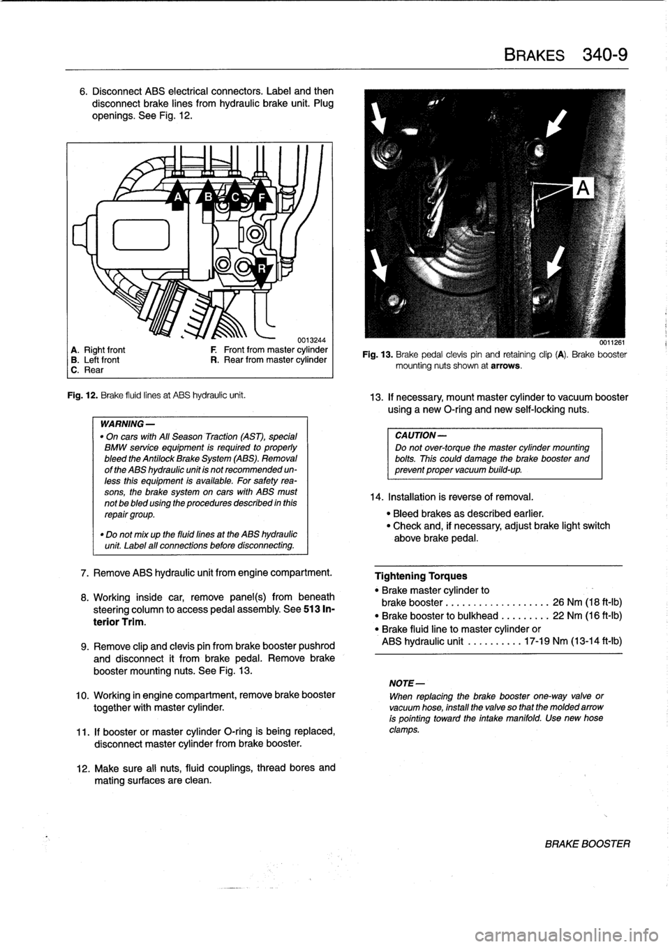
A
.
Right
front
F
Front
from
master
cylinder
B
.
Leftfront
R
.
Rear
from
master
cylinder
C
.
Rear
Fig
.
12
.
Brake
fluid
linesat
ABS
hydraulic
unit
.
WARNING
-
"
On
cars
with
All
Season
Traction
(AST),
special
BMW
service
equipment
is
required
to
properly
bleed
the
Antilock
Brake
System
(ABS)
.
Removal
of
the
ABS
hydraulic
unit
is
not
recommended
un-
less
this
equipment
is
available
.
For
safetyrea-
sons,
the
brake
system
on
cars
with
ABS
must
not
be
bled
using
the
procedures
described
inthis
repair
group
.
"
Do
not
mix
up
the
fluid
fines
at
the
ABS
hydraulic
unit
Label
all
connections
before
disconnecting
.
7
.
Remove
ABS
hydraulic
unit
from
engine
compartment
.
8
.
Working
inside
car,
remove
panel(s)
frombeneath
steering
column
to
access
pedal
assembly
.
See513
In-
terior
Trim
.
12
.
Make
sure
al¡
nuts,
fluid
couplings,
thread
bores
and
mating
surfaces
are
clean
.
BRAKES
340-
9
0011261
Fig
.
13
.
Brake
pedal
clevispin
and
retaining
clip
(A)
.
Brake
booster
mounting
nuts
shown
at
arrows
.
13
.
If
necessary,
mount
master
cylinder
to
vacuum
booster
using
a
new
O-ríng
and
newself-locking
nuts
.
CAUTION-
Do
not
over-torque
the
master
cylinder
mounting
bolts
.
This
could
damage
the
brake
booster
and
prevent
proper
vacuum
build-up
.
14
.
Installation
is
reverse
of
Rmoval
.
"
Bleed
brakes
as
described
earlier
.
"
Check
and,
if
necessary,
adjust
brake
light
switch
above
brake
pedal
.
Tightening
Torques
"
Brakemaster
cylinder
to
brake
booster
...........
.
..
..
...
26
Nm
(18
ft-Ib)
"
Brake
booster
to
bulkhead
.
.
..
..
...
22
Nm
(16
ft-Ib)
"
Brake
fluidline
to
master
cylinder
or
ABS
hydraulic
unit
.......
.
..
17-19
Nm
(13-14
ft-lb)
9
.
Remove
clip
and
clevis
pin
from
brake
booster
pushrod
and
disconnect
it
from
brakepedal
.
Remove
brake
booster
mounting
nuts
.
See
Fig
.
13
.
NOTE-
10
.
Working
in
engine
compartment,
remove
brake
booster
When
replacing
the
brake
booster
one-way
valve
or
together
with
master
cylinder
.
vacuum
hose,
install
the
valve
so
that
the
molded
arrow
is
pointing
toward
the
intake
manifold
.
Use
new
hose
11
.
If
booster
or
master
cylinder
O-ring
is
being
replaced,
clamps
.
disconnect
master
cylinder
from
brake
booster
.
BRAKE
BOOSTER