jack points BMW 328i 1993 E36 Workshop Manual
[x] Cancel search | Manufacturer: BMW, Model Year: 1993, Model line: 328i, Model: BMW 328i 1993 E36Pages: 759
Page 11 of 759

WARNING
-
"
Never
work
under
a
lifted
car
unless
it
is
solidly
supported
on
jack
stands
that
are
intended
for
that
purpose
.
Do
not
support
a
car
on
cinder
blocks,
bricks,
or
other
objects
that
may
shift
orcrumble
under
continuous
load
.
Never
work
un-
dera
car
that
is
supported
only
by
the
lifting
jack
.
"
Fuel
is
highly
flammable
.
When
working
around
fuel,
do
not
smoke
or
worknear
heaters
or
other
fire
hazards
.
Keepan
approved
fire
extinguisher
handy
.
"
llluminate
the
work
area
adequately
and
safely
.
Use
a
portable
safety
light
for
working
inside
or
under
thecar
.
A
fluorescent
type
lightis
best
be-
cause
it
gives
off
less
heat
.
If
using
a
light
with
anormal
incandescent
butb,
use
rough
service
bulbs
to
avoid
breakage
.
The
hot
filamentof
an
accidentallybroken
bulb
can
ignite
spilled
fuel
or
oil
"
Keep
sparks,
lighted
matches,
and
any
open
llame
away
from
thetop
of
the
battery
.
Hydrogen
gas
emitted
by
the
battery
is
highly
flammable
.
Any
nearby
source
of
ignition
may
cause
the
battery
to
explode
.
"
Never
¡ay
tools
or
parts
in
the
engine
compart-
ment
or
on
top
of
the
battery
.
They
may
fall
into
confined
spaces
and
be
difficult
toretrieve,
be-
come
caught
in
beits
or
other
rotating
parts
when
the
engine
is
started,
or
cause
electrical
shorts
anddamage
to
the
electrical
system
.
"
The
fuel
system
is
designed
to
retain
pressure
even
when
the
ignition
is
off
.
When
working
with
the
fuel
system,
loosen
the
fuel
fines
slowly
to
al-
low
the
residual
pressure
to
dissipate
gradually
.
Take
precautions
to
avoid
spraying
fuel
.
Lifting
the
Car
FUNDAMENTALS
FOR
THE
DO-ITYOURSELF
OWNER
010-
3
For
those
repairs
that
require
raising
the
car,
theproper
jack-
ing
points
should
beused
to
raise
thecar
safely
and
avoid
dam-
age
.
There
are
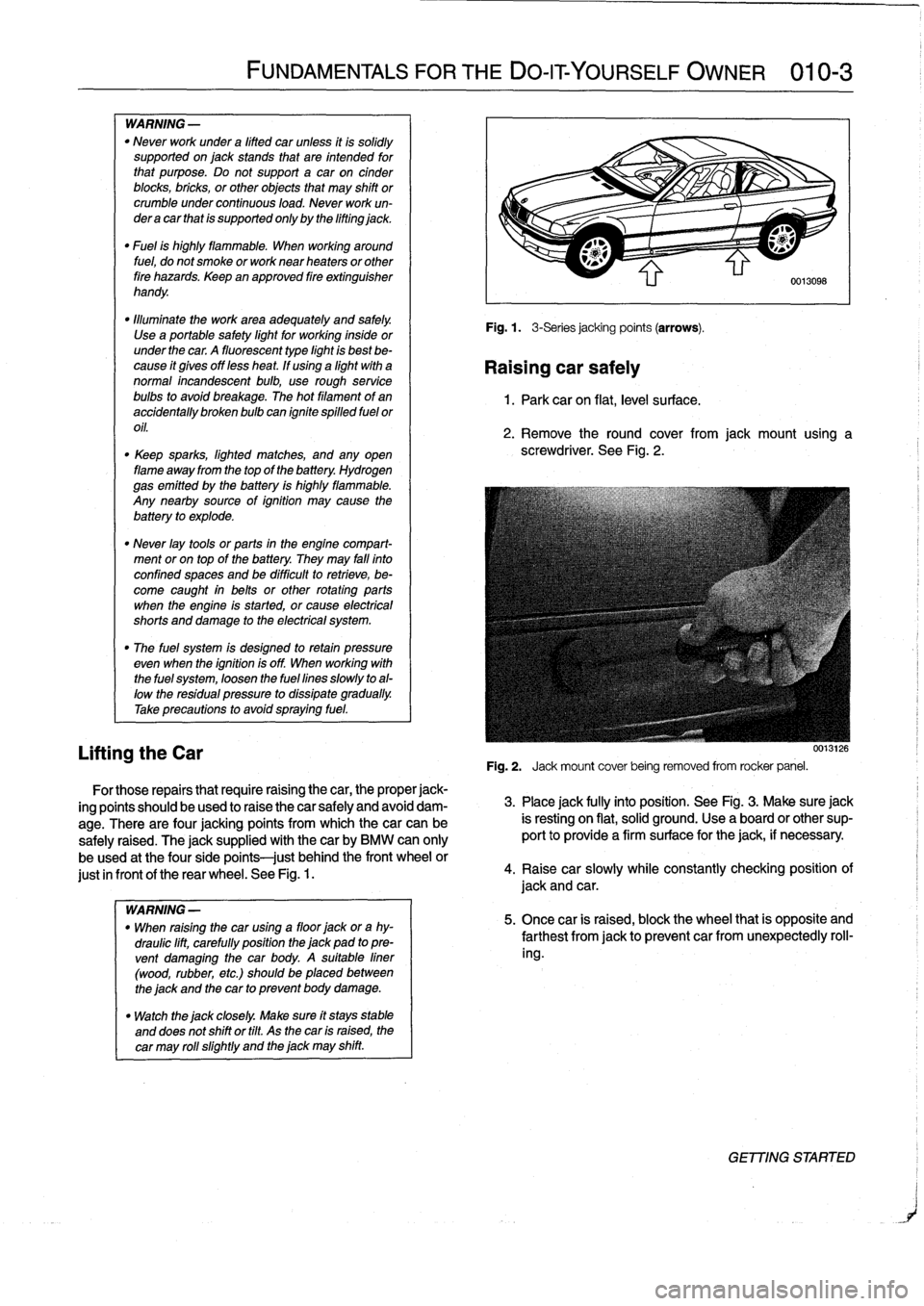
four
jacking
points
from
which
thecar
can
be
safely
raised
.
The
jacksupplied
with
thecar
by
BMW
can
only
be
used
at
the
fourside
points
just
behindthe
front
wheel
or
just
in
frontof
the
rear
wheel
.
See
Fig
.
1.
WARNING
-
"
When
raising
the
car
using
a
floor
jack
ora
hy-
draulic
lift,
carefully
position
the
jack
pad
topre-
vent
damaging
the
car
body
.
A
suitable
liner
(wood,
rubber,
etc
.)
should
be
placed
between
the
jack
and
the
car
to
prevent
body
damage
.
"
Watch
the
jack
closely
.
Make
sure
ft
stays
stable
and
does
not
shift
or
tilt
.
As
the
car
is
raised,
the
car
may
rol¡
slightly
and
the
jack
may
shift
.
Fig
.
1
.
3-Seriesjacking
points
(arrows)
.
Raising
car
safely
1
.
Park
car
on
flat,
leve¡
su
rface
.
2
.
Remove
the
round
cover
from
jack
mount
using
a
screwdriver
.
See
Fig
.
2
.
0013126
Fig
.
2
.
Jack
mount
cover
being
removed
from
rocker
panel
.
3
.
Place
jack
fully
into
position
.
See
Fig
.
3
.
Make
sure
jack
is
resting
on
flat,
solid
ground
.
Use
a
board
or
other
sup-
port
to
provide
a
firm
surface
for
the
jack,
if
necessary
.
4
.
Raisecar
slowly
while
constantly
checking
position
of
jack
and
car
.
5
.
Once
car
is
raised,
block
the
wheel
that
is
opposite
and
farthest
from
jackto
prevent
car
fromunexpectedly
roll-
ing
.
GET77NG
STARTER
Page 19 of 759

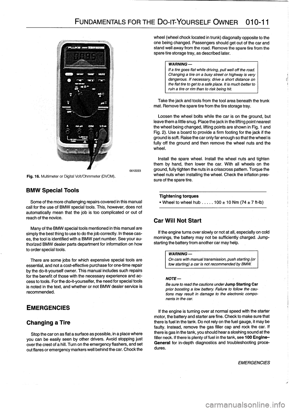
Fig
.
16
.
Multimeter
or
Digital
Volt/Ohmmeter
(DVOM)
.
BMW
Special
Tools
FUNDAMENTALS
FOR
THE
DO-ITYOURSELF
OWNER
010-11
0012223
Some
of
the
more
challenging
repairs
covered
in
this
manual
cal¡
for
the
use
of
BMW
special
tools
.
This,
however,
does
not
automatically
mean
that
thejob
is
too
complicated
or
out
of
reach
of
thenovice
.
Many
of
the
BMW
special
tools
mentioned
in
this
manual
are
simplythe
best
thing
to
use
to
do
thejob
correctly
.
In
these
cas-
es,
the
tool
is
identified
with
a
BMW
part
number
.
See
your
au-
thorized
BMW
dealer
parts
department
for
information
on
how
to
order
special
tools
.
There
are
some
jobs
for
which
expensive
special
tools
are
essential,
and
not
a
cost-effective
purchase
for
one-time
repair
by
the
do-it-yourself
owner
.
This
manual
includes
such
repairs
for
the
benefit
of
these
with
the
necessary
experience
and
ac-
cess
to
tools
.
For
the
do-it-yourselfer,
the
need
for
special
tools
is
noted
in
the
text,
and
whether
or
not
BMW
dealer
service
is
recommended
.
EMERGENCIES
Changing
a
Tire
Stop
thecar
onas
flat
a
surface
as
possible,
in
a
place
where
you
canbe
easily
seen
by
other
drivers
.
Avoid
stopping
just
over
the
crest
of
a
hill
.
Turnon
the
emergency
flashers,
and
set
out
(lares
or
emergency
markers
well
behindthecar
.
Chock
the
wheel
(wheel
chock
located
in
trunk)
diagonally
opposite
to
the
one
being
changed
.
Passengers
shouldgetout
of
thecar
and
stand
well
away
from
the
road
.
Remove
the
spare
tire
from
the
spare
tire
storage
tray,
as
described
later
.
WARNING
-
If
a
tire
goes
fíat
while
drtving,
pull
well
off
the
road
.
Changing
a
tire
ona
busy
street
or
highway
is
very
dangerous
.
If
necessary,
drive
a
short
distance
on
the
fíat
tire
to
get
to
a
sale
place
.
tt
is
much
better
to
ruin
a
tire
or
rim
than
to
risk
being
hit
.
Take
the
jack
and
tools
from
the
tool
area
beneath
the
trunk
mat
.
Remove
the
spare
tire
from
the
tire
storage
tray
.
Loosen
the
wheel
bolts
while
the
car
is
on
the
ground,
but
leave
them
a
little
snug
.
Placethe
jack
in
the
lifting
point
nearest
the
wheel
beingchanged,
lifting
points
are
shown
in
Fig
.
1
and
Fig
.
2)
.
Use
a
board
to
provide
a
firm
footing
for
the
jack
if
the
ground
is
soft
.
Raise
the
car
only
lar
enough
so
that
the
wheel
is
fully
off
the
ground
and
then
remove
the
wheel
nuts
and
the
wheel
.
Insta¡¡
the
spare
wheel
.
Install
the
wheel
nuts
and
tighten
them
by
hand,
then
lower
the
car
.
With
all
wheelson
the
ground,
fully
tighten
the
nuts
in
a
crisscross
pattern
.
Torque
the
wheel
nuts
when
installing
the
wheel
.
Check
the
inflation
pres-
sure
of
the
spare
tire
.
Tightening
torques
"
Wheel
to
wheel
hub
.....
100
t
10
Nm
(74
t
7
ft-Ib)
Car
Will
Not
Start
If
the
engine
tucos
over
slowly
or
not
at
all,
especially
on
cold
mornings,
the
battery
may
not
be
sufficiently
charged
.
Jump-
starting
the
battery
from
another
car
may
help
.
WARNING
-
On
carswith
manual
transmisston,
push
starting
(or
tow
starting)
acar
ts
not
recommended
by
BMW
.
NOTE-
Be
sure
to
read
the
cautions
underJump
Starting
Car
prior
boosting
a
low
battery
.
Fatlure
to
followthe
cau-
tions
may
result
in
damage
to
the
electronic
compo-
nents
in
the
car
.
If
the
engine
is
turning
over
at
normal
speed
with
the
starter
motor,
the
battery
and
starter
are
fine
.
Check
to
make
sure
that
there
is
fuel
in
the
tank
.
Do
not
rely
on
the
fuel
gauge,
it
may
be
faulty
.
Instead,
remove
the
gas
filler
cap
and
rock
thecar
.
If
there
is
gas
in
the
tank,
you
should
hear
a
sloshing
sound
at
the
filler
neck
.
lf
there
is
plenty
offuel
in
the
tank,
see100
Engine-
General
for
in-depth
diagnostics
and
troubleshootingproce-
dures
.
EMERGENCIES
Page 265 of 759

STABILIZER
BAR
Stabilizer
bar,
removing
and
installing
Stabilizer
bar
link
arrangements
differ
slightly
among
mod-
els
.
In
most
models
the
links
attach
lo
the
control
arms
near
the
outboard
end
.
OnM3
models
the
links
attach
lo
the
strut
assemblies
.
1
.
Raise
car
and
remove
both
front
wheels
.
WARNING
-
Make
sure
that
the
car
is
firmly
supported
on
jack
stands
desígned
for
the
purpose
.
Place
the
jack
stands
beneath
a
structural
chassís
point
.
Do
not
place
jack
stands
under
suspension
parts
.
uul
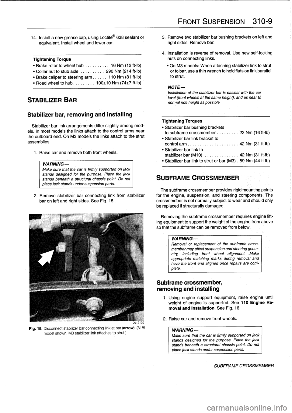
Fig
.
15
.
Disconnect
stabilizer
bar
connecting
link
at
bar
(arrow)
.
(3181
model
shown
.
M3
stabilizer
link
attaches
lo
strut
.)
FRONT
SUSPENSION
310-
9
14
.
Insta¡¡
a
new
grease
cap,
using
Loctite
©
638
sealant
or
3
.
Remove
two
stabilizer
bar
bushing
brackets
on
left
and
equivalent
.
Insta¡¡
wheel
and
lower
car
.
right
sides
.
Remove
bar
.
4
.
Installation
is
reverse
of
removal
.
Use
new
seif-lockíng
Tightening
Torque
núts
on
connecting
links
.
"
Brake
rotor
lo
wheel
hub
..........
16
Nm
(12
ft-Ib)
"
On
M3
models
:
When
attaching
stabilizer
link
lostrut
"
Collar
nut
lo
stubaxle
.
.........
290
Nm
(214
ft-Ib)
orlobar,
usea
thin
wrench
lo
hold
flats
on
link
parallel
"
Brake
caliper
losteering
arm
......
110
Nm
(81
ft-Ib)
lo
strut
.
"
Road
wheel
lo
hub
...
...
.
.
.
100±10
Nm
(74t7
ft-Ib)
NOTE-
Installation
of
the
stabilizer
bar
is
easiest
with
thecar
leve¡
(front
wheels
at
the
same
height),
and
as
near
to
normal
ride
height
as
possible
.
Tightening
Torques
"
Stabilizer
bar
bushing
brackets
lo
subframe
crossmember
...
..
.
..
.
22
Nm
(16
ft-Ib)
"
Stabilizer
bar
link
bracket
lo
control
arm
................
.
.
.
.
.
42
Nm
(31
ft-1b)
"
Stabilizer
bar
link
lo
stabilizer
bar
(M10)
.............
.
42
Nm
(31
ft-Ib)
"
Stabilizer
bar
link
lostrut
or
bar
(M3)
.
59
Nm
(44
ft-Ib)
SUBFRAME
CROSSMEMBER
The
subframe
crossmember
provides
rigid
mounting'poínts
2
.
Remove
stabilizer
bar
connecting
link
from
stabilizer
for
the
engine,
suspension,
and
steering
components
.
The
baron
left
and
right
sides
.
See
Fig
.
15
.
crossmember
is
not
normally
subject
lo
wear
and
should
ohly
be
replaced
if
structurally
damaged
.
Removing
the
subframe
crossmember
requires
engine
lift-
ing
equipment
lo
support
theweight
of
tfhe
engine
from
above
so
that
the
subframe
can
be
removed
from
below
.
WARNING-
Removal
or
replacement
of
the
subframe
cross-
member
may
affect
suspension
and
steering
geom-
etry,
including
front
wheel
afignment
.
Make
appropriate
matching
marks
during
removal
and
have
the
front
end
aligned
once
repairs
are
com-
plete
.
Subframe
crossmember,
removing
and
installing
1
.
Using
enginesupport
equipment,
raise
engine
until
weight
of
engine
is
supported
.
See
110EngineRe-
moval
and
Installation
.
See
Fig
.
16
.
2
.
Raise
car
andremove
front
wheels
.
WARNING-
Make
sure
that
the
car
is
firmly
supportedon
jack
stands
desígned
for
the
purpose
.
Place
the
jack
stands
beneatha
structural
chassís
point
Do
not
place
jack
standsundersuspension
parts
.
SUBFRAME
CROSSMEMBER
Page 284 of 759

330-
1
2
REAR
SUSPENSION
Upper
control
arm,
removing
and
installing
1.
Raise
rear
end
of
car
and
remove
wheel
.
WARNING
-
Make
sure
that
the
car
is
firmly
supportedon
jack
stands
designed
for
the
purpose
.
Place
the
jack
stands
beneatha
structural
chassis
point
.
Do
not
place
jack
stands
under
suspension
parts
.
2
.
Remove
drive
axle
as
described
earlier
.
3
.
Remove
stabilizer
bar
link
fromupper
control
arm
.
4
.
Support
trailing
arm
from
below
with
a
transmission
jackorequivalent
.
WARNING
-
It
is
recommended
that
a
retaining
chain
be
in-
stalled
between
the
bottom
coil
of
the
coil
spring
and
the
upper
control
arm
to
retain
thespring
in
case
of
accidental
release
.
Personal
injury
can
re-
sult
if
the
compressed
coil
spring
ís
not
released
slowly
and
carefully
.
5
.
Remove
lower
shock
absorber
bolt
.
Refer
to
Fig
.
18
.
Slowly
lower
trailing
arm
until
coil
spring
is
fully
re-
leased
.
Remove
restraining
chain
and
remove
spring
.
7
.
Installation
is
reverse
of
removal
.
"
Always
use
new
self-locking
nuts
.
"
Have
car
professionally
aligned
when
job
is
complete
.
"
Insta¡¡
drive
axle
as
described
earlier
.
Tightening
Torques
"
Drive
axleto
final
drive
flange
M8
Torx
bolt
..........
..
.
..
....
64
Nm
(47
ft-Ib)
M10
Torx
bolt
.........
..
..
.
...
100
Nm
(74
ft-Ib)
"
Shock
absorber
to
trailing
arm
..
..
..
77
Nm
(57
ft-Ib)
"
Upper
control
arm
to
final
drive
carrier
(M12
bolt)
...
..
.
77
Nm
(57
ft-Ib)
"
Upper
control
arm
to
trailing
arm
(M12
bolt)
.........
110
Nm
(81
ft-Ib)
Lower
control
arm,
1
.
Raise
rear
end
of
car
and
support
it
securely
on
jack-
stands
.
Remove
rear
wheel
.
2
.
Remove
both
lower
control
arm
mounting
bolts
.
FINAL
DRIVE
CARRIER
3
.
Use
a
soft
hammer
to
tap
control
arm
out
of
its
mount-
ing
points
.
4
.
Installation
is
reverse
of
removal
.
NOTE-
Use
a
new
bolt
and
washer
assembly
at
the
final
drive
carrier
mountíng
point
forthe
control
arm
.
Tightening
Torque
"
Lower
control
arm
to
final
drive
carrier
(M12
bolt)
......
77
Nm
(57
ft-Ib)
"
Lower
control
arm
to
trailing
arm
(M12
bolt)
....
..
.
..
110
Nm
(81
ft-Ib)
FINAL
DRIVE
CARRIER
Final
drive
carrier,
removing
and
installing
1
.
Raise
rear
end
of
car
and
support
it
securely
on
jack
stands
.
Remove
rear
wheels
.
2
.
Remove
driveshaft
.
See
260
Driveshaft
.
3
.
Remove
both
drive
axles
as
described
earlier
.
6
.
Remove
both
upper
control
arm
mounting
bolts
.
Re-
move
control
arm
.
4
.
Disconnect
stabilizer
bar
from
upper
control
arms
.
Re-
move
stabilizer
bar
mounts
.
5
.
Disconnect
speedometer
harness
connector
on
final
drive
(where
applicable)
.
6
.
Remove
rear
section
of
exhaust
system
.
See
180
Ex-
haust
System
.
NOTE-
It
may
be
easier
to
remove
complete
exhaust
asonepiece
.
See
180
Exhaust
System
.
7
.
Remove
upper
and
lower
control
arms
as
described
earlier
.
8
.
Support
final
drive
carrierwith
transmissíon
jack
.
Re-
move
mounting
bolts
and
nuts
at
final
drive
carrier
bushing
mounts
.
See
Fig
.
22
.
9
.
Slowly
lower
final
drive
and
final
drive
carrier,
detaching
removing
and
installing
wire
harness
and
connectors
as
necessary
.
10
.
Finaldrive
may
now
be
unbolted
from
final
drive
carrier
.