lights BMW 328i 1994 E36 Owner's Guide
[x] Cancel search | Manufacturer: BMW, Model Year: 1994, Model line: 328i, Model: BMW 328i 1994 E36Pages: 759
Page 418 of 759
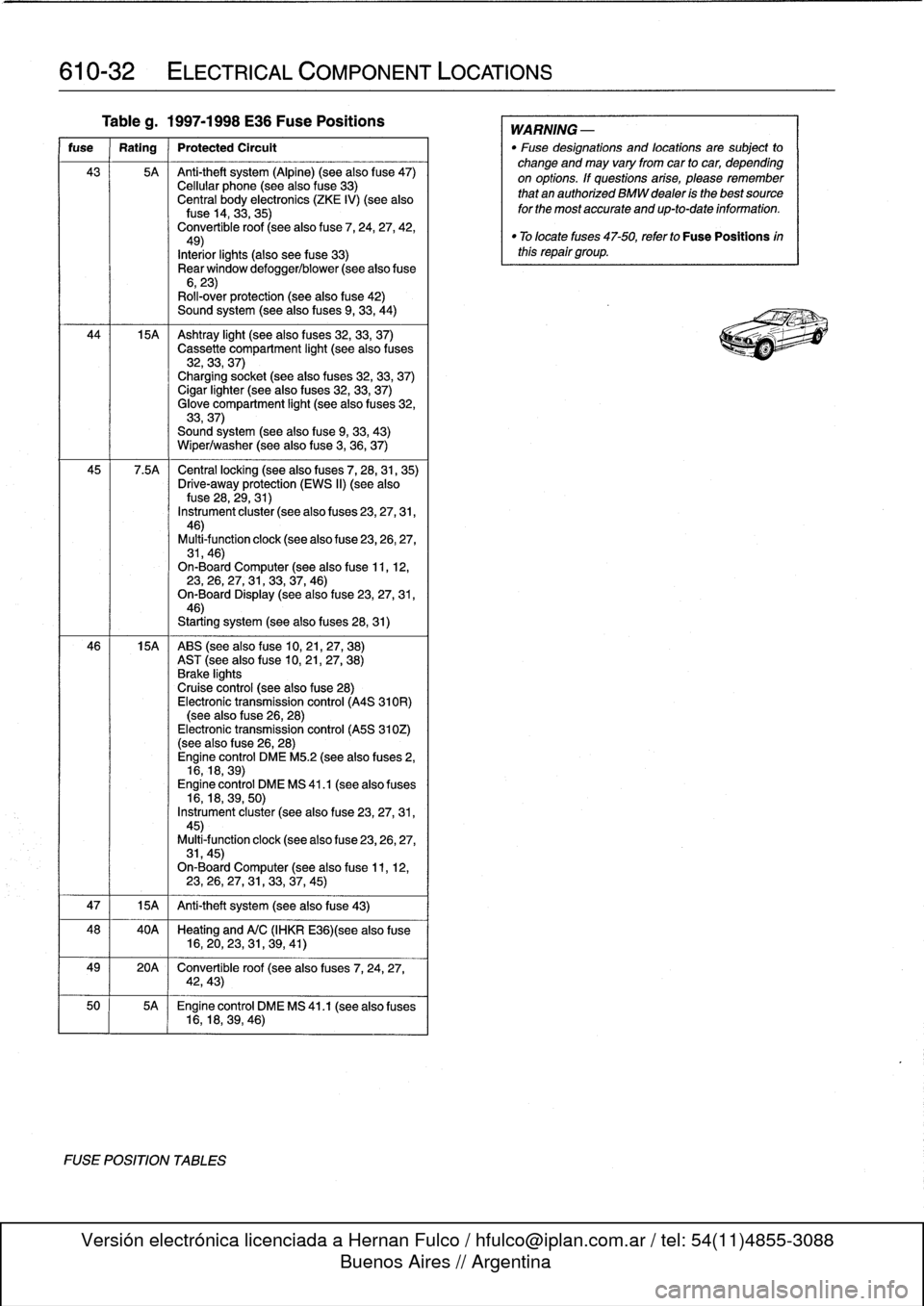
610-32
ELECTRICAL
COMPONENT
LOCATIONS
Tableg
.
1997-1998
E36
Fuse
Positions
fuse
Rating
Protected
Circult
43
5A
Anti-theft
system
(Alpine)
(see
also
f
use47)
Cellular
phone
(seealso
fuse
33)
Central
body
electronics
(ZKE
IV)
(see
alsofuse
14,
33,35)
Convertible
roof
(seealso
fuse
7,
24,
27,
42,49)
Interiorlights
(also
see
fuse
33)
Rear
window
defogger/blower
(see
alsofuse
6,23)
Roll-over
protection
(see
also
fuse
42)
Sound
system
(seealso
fuses
9,
33,
44)
44
15A
Ashtray
light
(seealso
f
uses
32,
33,
37)
Cassette
compartment
light
(seealso
fuses
32,33,
37)
Charging
socket
(seealso
fuses
32,33,
37)
Cigar
lighter
(seealso
fuses
32,33,
37)
Glove
compartment
light
(seealso
f
uses
32,
33,37)
Sound
system
(seealsofuse
9,
33,
43)
Wiper/washer
(seealsofuse
3,
36,
37)
45
7
.5A
Central
locking
(see
also
fuses
7,
28,31,
35)
Drive-away
protection
(EWS
II)
(see
alsofuse
28,
29,31)
Instrument
cluster
(see
also
f
uses
23,27,31,
46)
Multi-function
clock
(see
also
f
use
23,26,27,
31,46)
On-Board
Computer
(see
alsofuse
11,
12,23,
26,27,
31,33,37,
46)
On-Board
Display
(seealsofuse
23,27,31,
46)
Starting
system
(seealso
fuses
28,31)
46
15A
ABS
(see
also
fuse
10,21,27,
38)
AST
(seealsofuse
10,
21,27,
38)
Brake
lights
Cruise
control
(see
also
fuse
28)
Electronic
transmission
control
(A4S
310R)
(see
also
fuse
26,
28)
Electronic
transmission
control
(A5S
310Z)
(see
also
f
use
26,28)
Engine
control
DME
M5
.2
(see
also
fuses
2,
16,18,
39)
Engine
control
DME
MS
41
.1
(seealso
fuses
16,18,39,
50)
Instrument
cluster
(see
also
fuse
23,27,31,
45)
Multi4unction
clock
(see
also
fuse
23,26,27,
31,45)
On-Board
Computer
(seealsofuse
11,
12,23,26,27,
31,
33,37,
45)
47
1
15A
1
Anti-theft
system
(see
also
fuse
43)
48
40A
Heating
and
A/C
(IHKR
E36)(see
also
fuse
16,20,23,
31,
39,
41)
49
20A
Convertible
roof
(see
also
fuses
7,
24,
27,
42,43)
50
5A
Engine
control
DME
MS
41
.1
(seealso
fuses
16,18,39,
46)
FUSE
POSITION
TABLES
WARNING
-
"
Fuse
designations
and
locations
are
subject
to
change
and
may
vary
fromcar
to
car,
depending
on
options
.
If
questions
arise,
please
remember
that
an
authorized
BMW
dealer
is
the
bestsource
for
the
most
accurate
and
up-to-date
information
.
"
Tolocate
fuses
47-50,
refer
to
Fuse
Positions
inthis
repair
group
.
Page 429 of 759
612
Switches
and
Electrical
Accessories
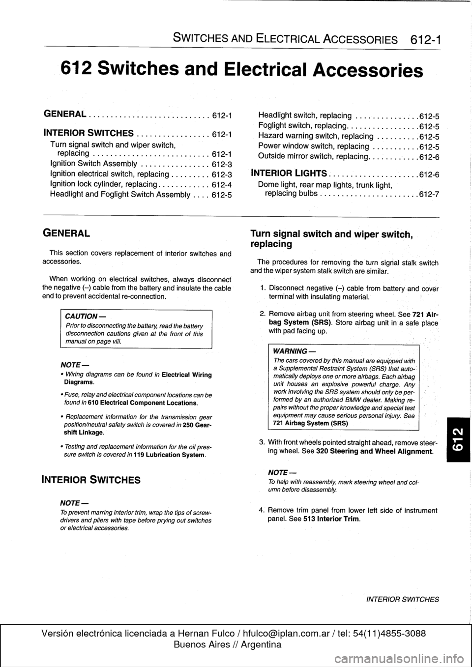
GENERAL
.
.
.
.
.
.
.
.
.
...
.
.
.
.
.
...
.
......
.612-1
Headlight
switch,
replacing
..
.
...
.
.
.
.
.
.
.
.
.
612-5
Foglight
switch,
replacing
....
.
.
.
.
.
.
.
.
.
.
.
.
.
612-5
INTERIOR
SWITCHES
.
.
...
.
.
.
.
.
.
.
.....
612-1
Hazard
warning
switch,
replacing
.
.
.
.
.
.
.
.
.
.612-5
Turn
signal
switch
and
wiper
switch,
Powerwindow
switch,
replacing
.
.
.
...
.
.
.
.
.
612-5
replacing
.
.
.
.
.
.
.
...
.
.
.
.....
.
....
.
.
.
.
612-1
Outside
mirrorswitch,
replacing
.
.
.
.
.....
.
.
.612-6
Ignition
Switch
Assembly
.
.
.
.
.
.
.
.
....
.
...
612-3
Ignition
electrical
switch,
replacing
.
...
.
....
612-3
INTERIOR
LIGHTS
.
.
................
.
..
612-6
Ignition
lock
cylinder,
replacing
.
.
.
.
.....
.
..
612-4
Dome
light,
rear
map
lights,
trunk
light,
Headlight
and
Foglight
Switch
Assembly
.
.
.
.
612-5
replacing
bulbs
.
......
.
.
.
.
.
.
.
.
.
.....
.
.612-7
GENERAL
Turn
signal
switch
and
wiper
switch,
replacing
Thissection
covers
replacement
of
interior
switches
and
accessories
.
The
procedures
for
removing
the
turn
signal
stalk
switch
and
the
wiper
system
stalk
switchare
similar
.
When
working
on
electrical
switches,
always
disconnect
the
negative
(-)
cable
from
the
battery
and
insulate
the
cable
end
to
prevent
accidental
re-connection
.
CAUTION-
Prior
to
disconnectiog
the
battery,
read
the
battery
disconnection
cautions
given
at
the
front
of
this
manual
on
page
viii
.
WARNING
-
The
cars
covered
by
this
manual
are
equipped
with
a
Supplemental
Restraint
System
(SRS)
that
auto-'
matically
deploys
one
or
more
airbags
.
Each
airbag
unit
houses
an
explosive
powerful
charge
.
Any
work
involving
the
SRS
system
should
only
be
per-
formed
byan
authorized
BMW
dealer
.
Making
re-
pairs
without
the
proper
knowledge
and
special
test
equipment
may
cause
serious
personal
injury
.
See
721
Airbag
System
(SRS)
3
.
With
front
wheels
pointed
straight
ahead,
remove
steer-
"
Testing
and
replacement
information
for
the
oil
ores-
¡ng
wheel
.
See
320
Steering
and
Wheel
Alignment
.
sure
switch
is
covered
in
119
Lubrication
System
.
NOTE-
"
Wirfng
diagramscan
be
found
in
Electrical
Wiring
Diagrams
.
"
Fuse,
relay
and
electrical
component
locations
can
be
found
in
610
Electrical
Component
Locations
.
"
Replacement
information
for
thetransmission
gear
position/neutral
safety
switch
is
covered
in
250
Gear-
shift
Unkage
.
INTERIOR
SWITCHES
NOTE
-
To
preventmarring
interior
trim,
wrap
the
tips
of
screw-
drivers
and
pliers
with
tape
beforeprying
out
switches
or
electrical
accessories
.
SWITCHES
AND
ELECTRICAL
ACCESSORIES
612-1
1
.
Disconnect
negative
(-)
cable
from
battery
and
cover
terminal
with
insulating
material
.
2
.
Remove
airbag
unit
from
steering
wheel
.
See
721
Air-
bag
System
(SRS)
.
Store
airbag
unit
in
a
safe
placew¡th
pad
facing
up
.
NOTE
-
To
helo
with
reassembly,
mark
steering
wheel
and
col-
umn
before
disassembly
.
4
.
Remove
trim
panel
from
lower
left
side
of
instrument
panel
.
See513
Interior
Trim
.
INTERIOR
SWITCHES
Page 433 of 759
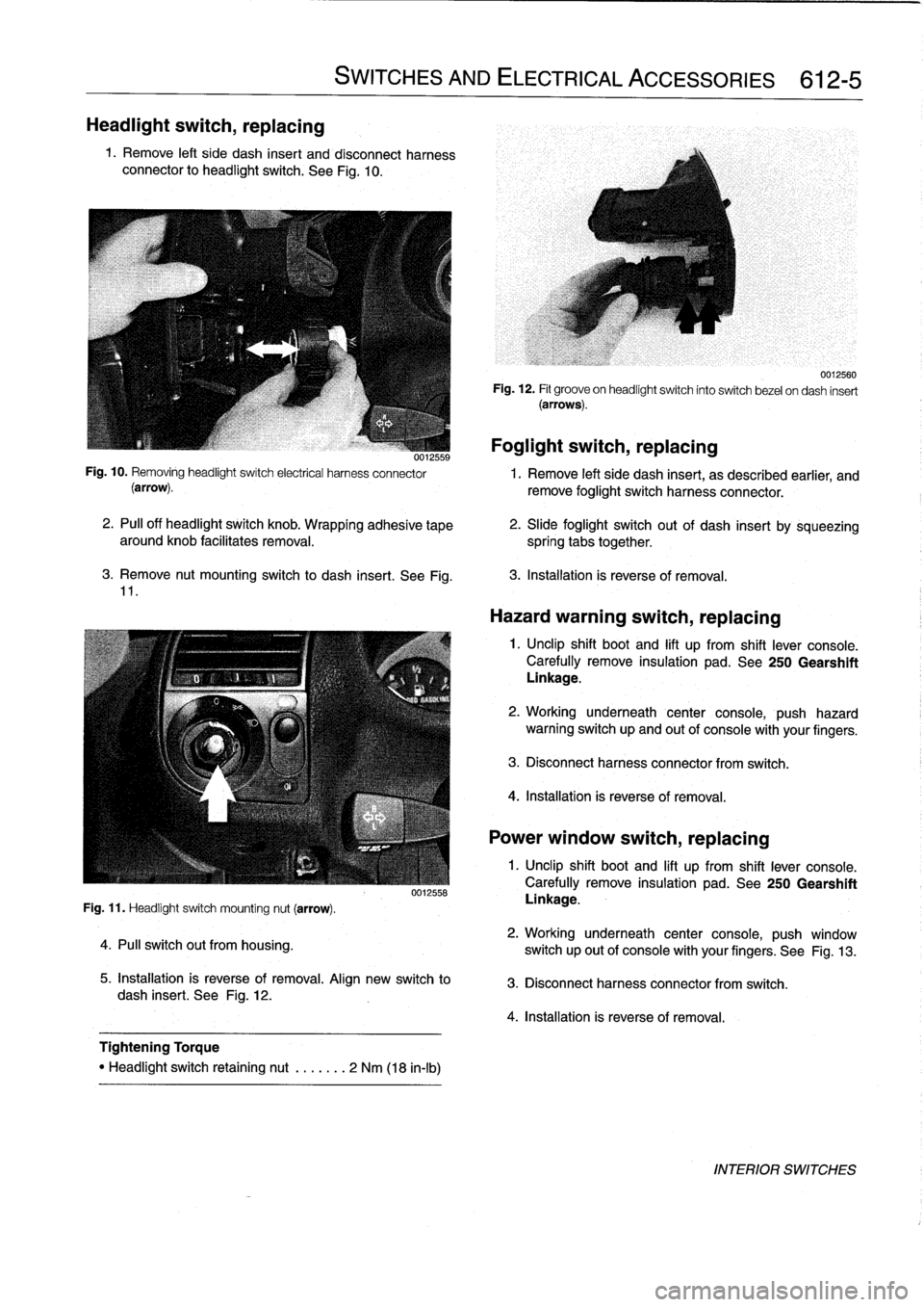
Headlight
switch,
replacing
1
.
Remove
left
side
dash
insert
and
disconnect
harness
connector
to
headlight
switch
.
See
Fig
.
10
.
3
.
Remove
nut
mounting
switch
to
dash
insert
.
See
Fig
.
11
.
Fig
.
11
.
Headlight
switch
mounting
nut
(arrow)
.
4
.
Pull
switch
out
from
housing
.
SWITCHES
AND
ELECTRICAL
ACCESSORIES
612-5
0012558
5
.
Installation
is
reverse
of
removal
.
Align
new
switch
to
dash
insert
.
See
Fig
.
12
.
Tightening
Torque
"
Headlight
switch
retaining
nut
.
......
2
Nm
(18
in-lb)
Foglight
switch,
replacing
0012559
Fig
.
10
.
Removing
headlightswitch
electrical
harness
connector
1
.
Remove
left
side
dash
insert,
as
described
earlier,
and
(arrow)
.
remove
foglight
switch
harness
connector
.
2
.
PA
off
headlight
switch
knob
.
Wrapping
adhesive
tape
aroundknob
facilitates
removal
.
spring
tabs
together
.
0012560
Fig
.
12
.
Fit
groove
on
headlightswitch
into
switch
bezel
ondash
insert
(arrows)
.
2
.
Slide
foglight
switch
out
of
dash
insert
by
sqúeezing
3
.
Installation
is
reverse
of
removal
.
Hazard
warning
switch,
replacing
1
.
Unclip
shift
boot
and
lift
up
from
shift
lever
console
.
Carefully
remove
insulation
pad
.
See
250
Gearshift
Linkage
.
2
.
Working
underneath
center
console,
push
hazard
warning
switch
up
and
out
of
console
with
your
fingers
.
3
.
Disconnect
harness
connector
from
switch
.
4
.
Installation
is
reverse
of
removal
.
Power
window
switch,
replacing
1
.
Unclip
shift
boot
and
lift
up
from
shift
lever
console
.
Carefully
remove
insulation
pad
.
See250
Gearshift
Linkage
.
2
.
Working
underneath
center
console,
push
window
switch
up
out
of
console
with
your
fingers
.
See
Fig
.
13
.
3
.
Disconnect
harness
connector
from
switch
.
4
.
Installation
is
reverse
of
removal
.
INTERIOR
SWITCHES
Page 434 of 759
612-6
SWITCHES
AND
ELECTRICAL
ACCESSORIES
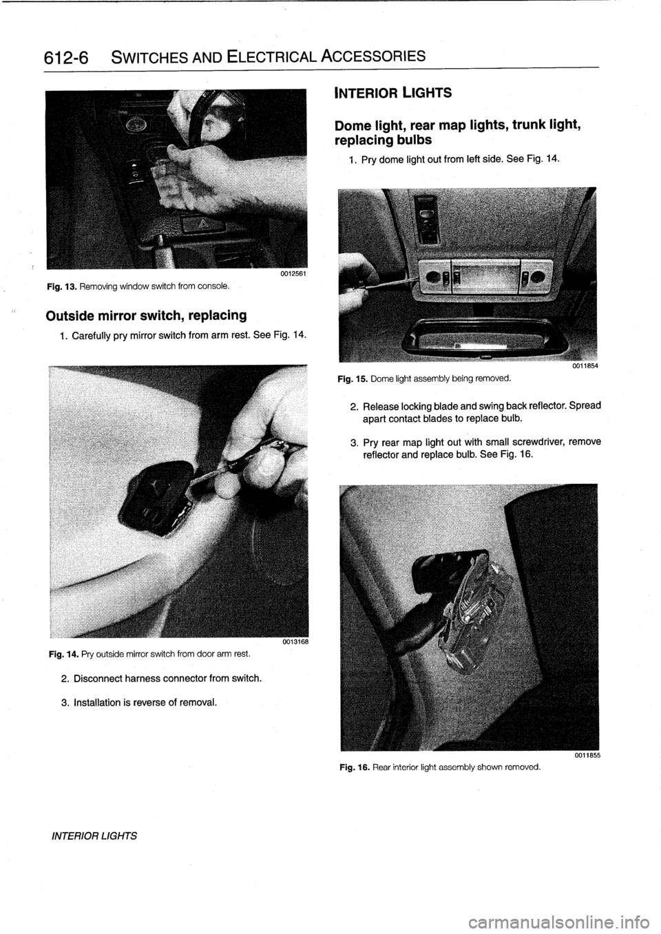
Fig
.
13
.
Removing
window
switch
from
console
.
Outside
mirror
switch,
replacing
0012561
1
.
Carefully
pry
mirror
switch
from
arm
rest
.
See
Fig
.
14
.
Fig
.
14
.
Pry
outside
mirror
switch
from
door
arm
rest
.
2
.
Disconnectharness
connector
from
switch
.
3
.
Installation
is
reverseof
removal
.
INTERIOR
LIGHTS
0013168
INTERIOR
LIGHTS
Dome
light,
rear
map
lights,
trunk
light,
replacing
bulbs
1
.
Pry
dome
light
out
from
left
side
.
See
Fig
.
14
.
Fig
.
15
.
Dome
light
assembly
being
removed
.
2
.
Release
locking
blade
and
swing
back
reflector
.
Spread
apart
contact
blades
toreplace
buib
.
3
.
Pry
rear
map
light
out
with
small
screwdriver,
remove
reflector
and
replace
bulb
.
See
Fig
.
16
.
Fig
.
16
.
Rear
interior
light
assembly
shown
removed
.
0011855
Page 435 of 759
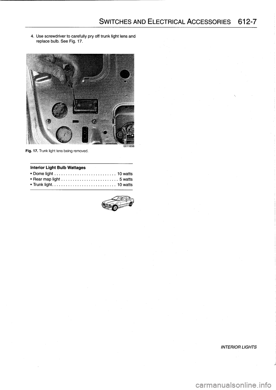
4
.
Use
screwdriver
to
carefully
pry
off
trunk
light
lens
and
replace
bulb
.
See
Fig
.
17
.
Fig
.
17
.
Trunk
light
lens
being
removed
.
Interior
Light
Bulb
Wattages
"
Dome
light
..
..
.
..
..
..................
10
watts
"
Rear
map
light
.
.
.
.
.
....................
5
watts
"
Trunk
light
...
..
.
..
....................
10
watts
SWITCHES
AND
ELECTRICAL
ACCESSORIES
612-7
uulio56
INTERIOR
LIGHTS
Page 438 of 759
620-2
INSTRUMENTS
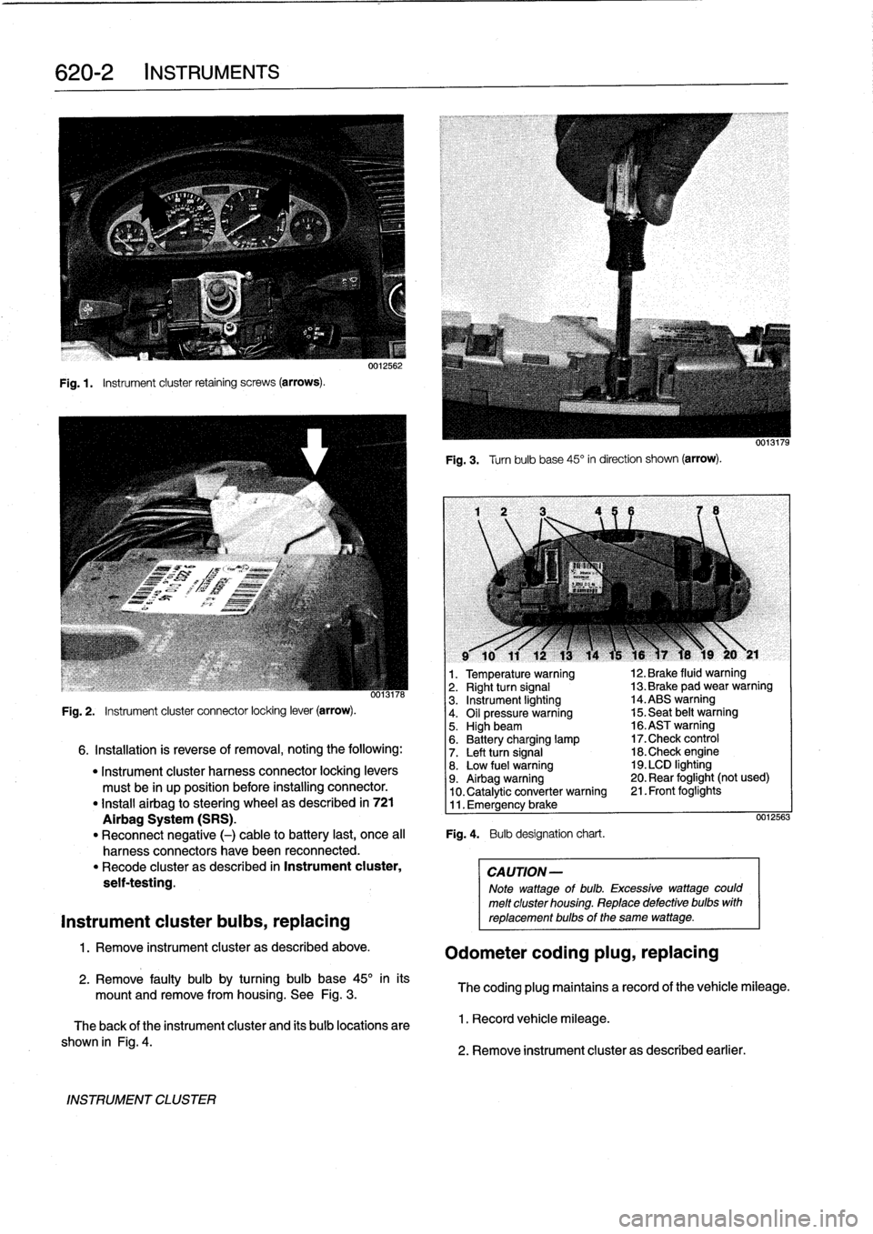
Fig
.1.
Instrument
cluster
retaining
screws
(arrows)
.
INSTRUMENT
CLUSTER
0012562
Fig
.
3
.
Turnbulb
base
45°
in
direction
shown
(arrow)
.
l
v
w
r
v
9
10
11
12
13
14
15
16
)7
18
19
20
y
21
1
.
Temperature
warning
12
.
Brake
fluid
warning
oo13n6
2
.
Right
turn
signal
13
.
Brake
pad
wear
warning
3
.
Instrument
lighting
14
.ABS
warning
Fig
.
2
.
Instrument
cluster
connector
locking
lever
(arrow)
.
4
.
Oil
pressure
warning
15
.
Seat
belt
warning5
.
Highbeam
16
.ASTwarning
6
.
Battery
charging
lamp
17
.Check
control
6
.
Installation
is
reverse
of
removal,
noting
the
following
:
7
.
Left
turn
signal
18
.Check
engine
"
Instrument
cluster
harness
connector
locking
levers
8
.
Low
fuel
warning
19
.
LCD
lighting
must
be
in
up
position
before
installing
connector
.
9
.
Airbag
warning
20
.
Rear
foglight
(not
used)
10
.
Catalytic
converter
warning
21
.
Front
foglights
"
Install
airbag
to
steering
wheel
as
described
in
721
11
.
Emergency
brake
Airbag
System
(SRS)
.
0012563
"
Reconnect
negative
(-)
cable
to
battery
last,
once
al¡
Fig
.
4
.
Bulb
designation
chart
.
harness
connectors
have
been
reconnected
.
"
Recode
cluster
as
described
in
Instrument
cluster,
CAUTION-
seif-testing
.
Note
wattage
of
bulb
.
Excessive
wattage
could
melt
cluster
housing
.
Replace
defective
bulbs
with
Instrument
cluster
bulbs,
replacing
reptacementbulbs
of
the
same
wattage
.
1
.
Remove
instrument
cluster
as
described
above
.
Odometer
coding
plug,
replacing
2
.
Remove
faulty
bulb
by
turning
bulb
base
45°
inits
mount
and
remove
from
housing
.
See
Fig
.
3
.
The
coding
plug
maintains
a
record
of
thevehicle
mileage
.
The
back
of
the
instrument
cluster
and
its
bulb
locations
are
1
.
Record
vehicle
mileage
.
shown
in
Fig
.
4
.
2
.
Remove
instrument
cluster
as
described
earlier
.
Page 441 of 759
FRONT
LIGHTING
.
...........
.
....
.
.
.
.
630-1
Headlight
buib,
replacing
............
.
.
.
.
630-1
Headlight
assembly,
removing
and
installing
.......
.
....
.
.
.
.
630-2
Foglight
assembly,
removing
and
installing
..
630-3
Front
turn
signal
assembly,
removing
and
installing
.....
.
.
.
........
630-4
GENERAL
The
headlight
and
foglight
assemblies
usehalogen
bulbs
.
To
ensure
the
longevity
of
halogen
bulbs,
the
bulb
glass
should
not
be
handied
.
Dirt
and
skin
oíls
may
cause
a
bulbto
fail
prematurely
.
If
necessarywipe
bulb
using
a
clean
cloth
dampened
with
rubbing
alcohol
.
NOTE-
Use
only
original
equipment
replacement
bulbs
.
Non-
original
equipment
bulbs
may
cause
false
failure
read-
ings
on
the
check
control
display
(where
applicable)
.
WARNING
-
INhenworking
on
electrical
systems,
remove
the
fuse
protecting
the
circuit
under
repair
.
See
610
Electrical
Component
Locations
.
FRONT
LIGHTING
Headlight
bulb,
replacing
1
.
Open
engine
hood
.
2
.
Working
in
back
of
headlight
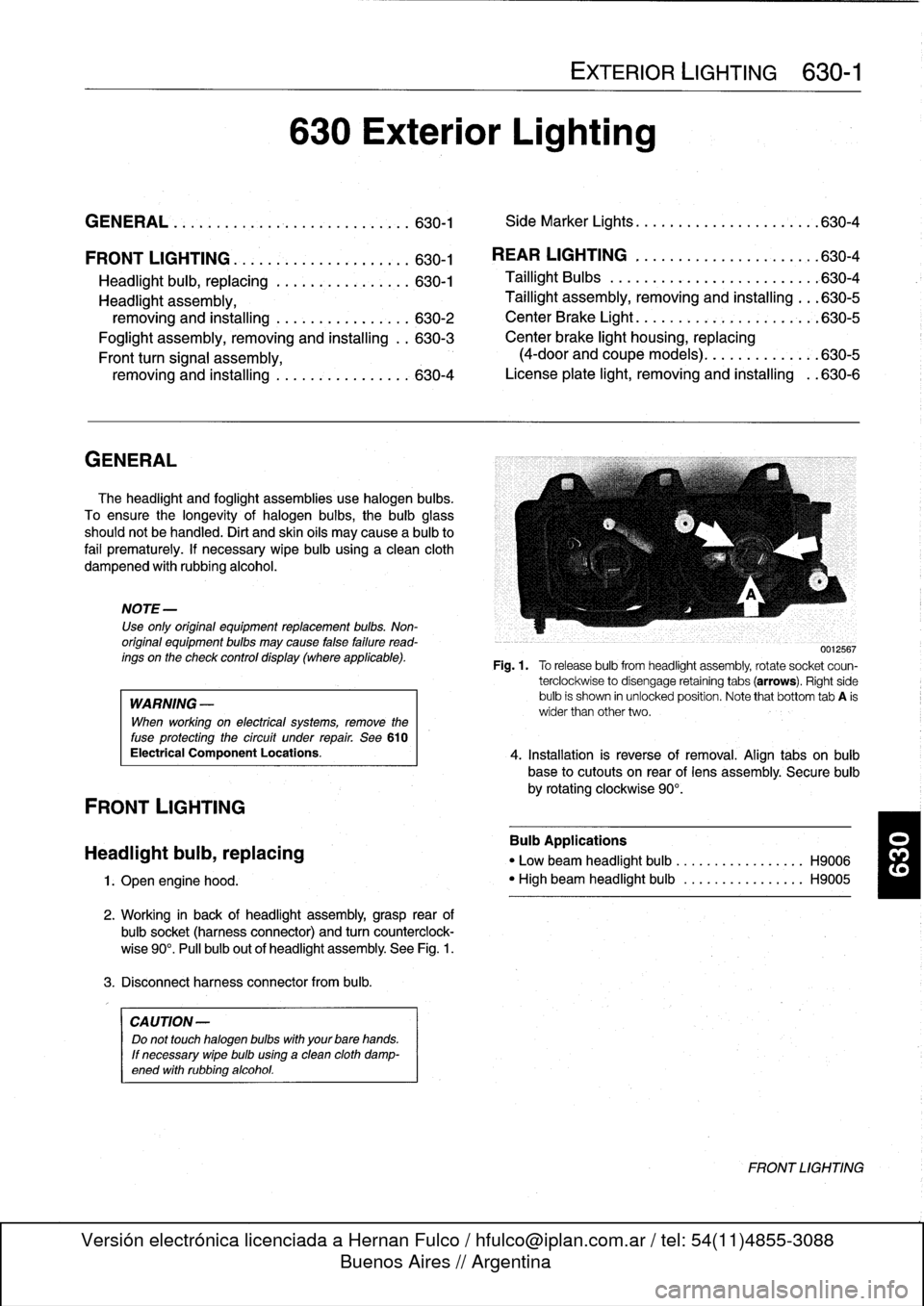
assembly,grasp
rear
of
bulbsocket
(harnessconnector)
and
turn
counterclock-
wise
90°
.
Pull
bulb
out
of
headlight
assembly
.
See
Fig
.
1
.
3
.
Disconnect
harness
connector
from
bulb
.
CA
UTION-
Do
not
touch
halogen
bubs
with
yourbare
hands
.
If
necessary
wipe
bulb
using
a
clean
cloth
damp-
ened
with
rubbing
alcohol
.
630
Exterior
Lighting
EXTERIOR
LIGHTING
630-1
GENERAL
.
.
.
.
...
.
................
.
.
.
.
630-1
Side
Marker
Lights
.......
.
.
.
.
.
.......
.
..
630-4
REAR
LIGHTING
.
......
.
.
.
.
.
.
.
...
.
.
.
..
630-4
Taillight
Bulbs
..........
.
.
.
.
.
.....
.
.
.
.
.
630-4
Taillight
assembly,
removing
and
installing
.
.
.
630-5
CenterBrake
Light
.......
.
.
.
.
.
.
.
.
.
.
.
.
.
.
.
630-5
Center
brake
light
housing,
replacing
(4-door
and
coupe
models)
.
.
.
.
.......
.
.
.630-5
License
plate
light,
removingand
installing
.
.630-6
0012567
Fig
.1.
Torelease
bulbfrom
headlight
assembly,
rotate
socket
coun-
terclockwise
to
disengage
retaining
tabs
(arrows)
.
Right
side
bulb
is
shown
in
unlocked
position
.
Note
that
bottom
tab
A
is
wider
than
other
two
.
4
.
Installation
is
reverse
of
removal
.
Align
tabs
on
bulb
base
to
cutouts
on
rear
of
lens
assembly
.
Secure
bulb
by
rotating
clockwise
90°
.
Bulb
Applications
"
Low
beam
headlight
bulb
...
.
..
..
.........
H9006
"
High
beam
headlight
bulb
..
.
..
..
.........
H9005
FRONT
LIGHTING
Page 444 of 759
630-
4
EXTERIOR
LIGHTING
Front
turn
signal
assembly,
Side
Marker
Lights
removing
and
installing
Side
marker
lights
on
later
model
E36
cars
are
snapped
into
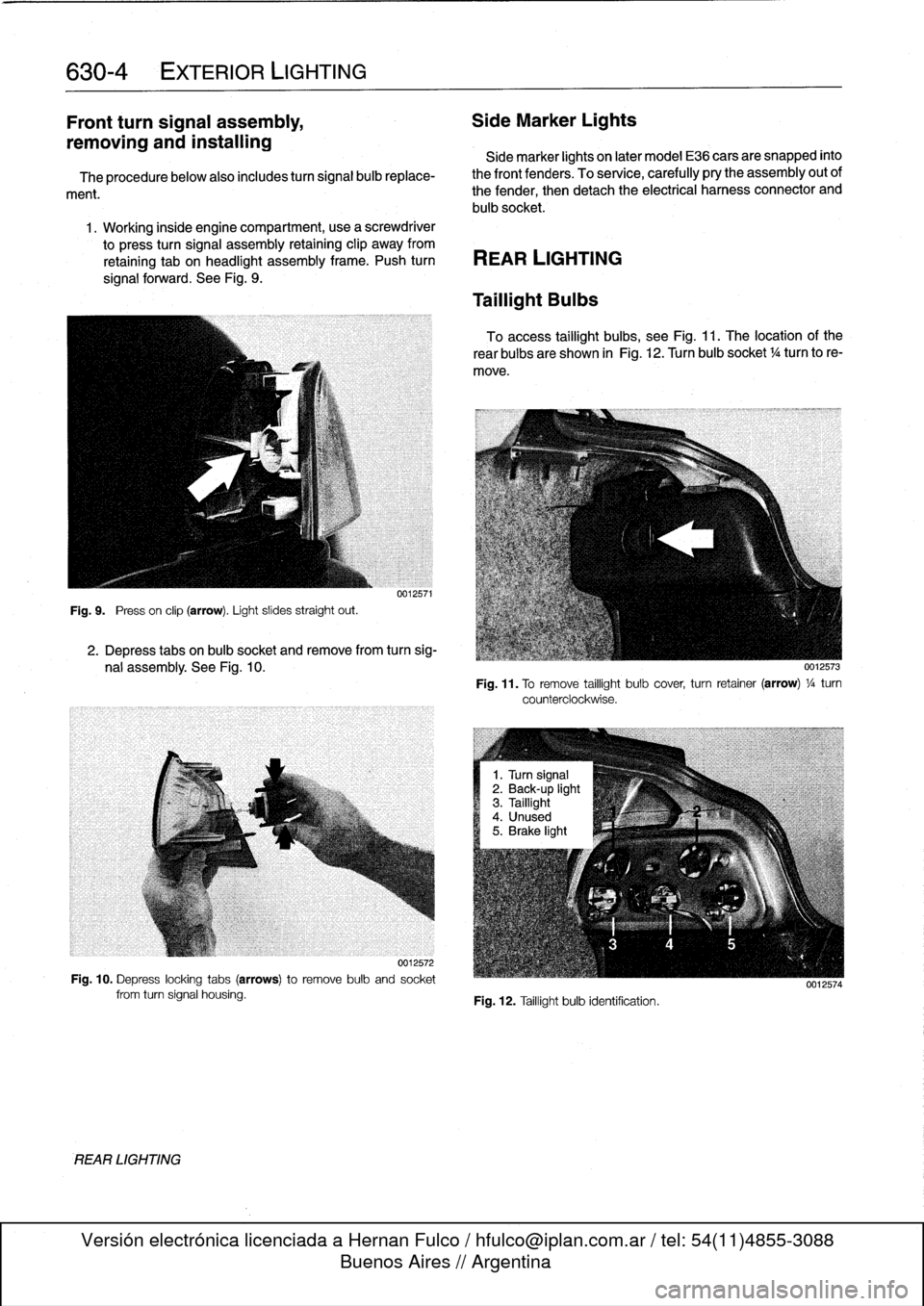
The
procedurebelow
also
includes
turn
signal
bulb
replace-
the
front
fenders
.
To
service,
carefully
pry
the
assembly
out
of
ment
.
the
fender,
then
detach
the
electrical
harness
connector
and
bulb
socket
.
1
.
Working
inside
engine
compartment,usea
screwdriver
to
press
turn
signal
assembly
retaining
clip
away
from
retaining
tab
on
headlight
assembly
frame
.
Push
turn
REAR
LIGHTING
signal
forward
.
See
Fig
.
9
.
Fig
.
9
.
Press
on
clip
(arrow)
.
Light
slides
straight
out
.
REAR
LIGHTING
0012571
2
.
Depress
tabs
on
bulb
socket
and
remove
from
turn
sig-
nal
assembly
.
See
Fig
.
10
.
0012572
Fig
.
10
.
Depress
locking
tabs
(arrows)to
remove
bulb
and
socket
from
turn
signal
housing
.
Taillight
Bulbs
To
access
taillight
bulbs,
see
Fig
.
11
.
The
location
of
the
rear
bulbs
are
shown
in
Fig
.
12
.
Turn
bulb
socket
1
/4turn
to
re-
move
.
Fig
.
11
.
To
remove
taillight
bulb
cover,
turn
retainer
(arrow)
1
/a
turn
counterclockwise
.
Fig
.
12
.
Taillight
bulb
identification
.
0012574
Page 485 of 759
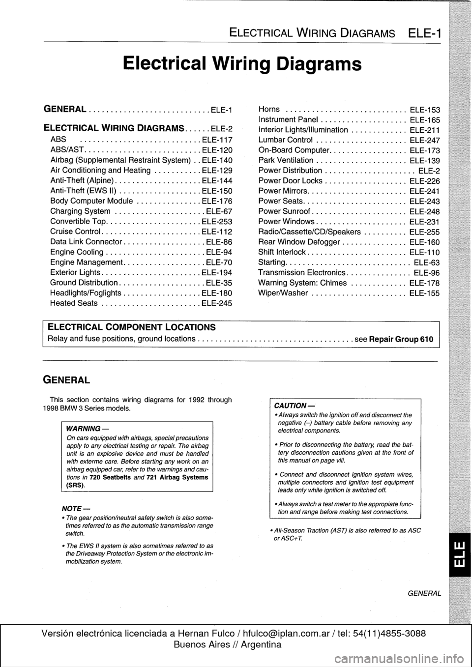
GENERAL
This
section
contains
wiring
diagrams
for
1992
through
1998
BMW
3
Series
models
.
WARNING
-
On
cars
equipped
with
airbags,
special
precautions
apply
to
any
electrical
testing
or
repair
.
The
airbag
unit
is
an
explosive
device
and
must
be
handled
with
exterme
care
.
Before
starting
any
work
onan
airbag
equipped
car,
refer
to
the
warnings
and
cau-
tions
in
720
Seatbelts
and
721
Airbag
Systems
(SRS)
.
NOTE-
The
"
gear
position/neutral
safetyswitch
is
also
some-
timesreferred
to
as
the
automatic
transmission
range
switch
.
"
The
EWS
11
system
is
also
sometimes
referred
to
as
the
Driveaway
Protection
System
or
the
electronic
im-
mobilization
system
.
ELECTRICAL
WIRING
DIAGRAMS
ELE-1
Electrical
Wiring
Diagrams
GENERAL
.
.
.
.
.
.
.
.
.
................
.
.
.
ELE-1
Horns
.....
.
.....
.
.
.
....
.
.
.
.
.
...
.
.
ELE-153
Instrument
Panel
.
.
.
.
.
.
..............
ELE-165
ELECTRICAL
WIRING
DIAGRAMS
...
.
.
.
ELE-2
Interior
Lights/Illumination
.............
ELE-211
ABS
..............
.
.
.
.....
.
.....
ELE-117
Lumbar
Control
.
....................
ELE-247
ABS/AST
.............
.
.
.
...
.
.
.
.....
ELE-120
On-Board
Computer
..................
ELE-173
Airbag
(Supplemental
Restraint
System)
..
ELE-140
Park
Ventilation
.
.
.
...........
.
...
.
..
ELE-139
Air
Conditioning
and
Heating
.
.
.
.
.
.
.....
ELE-129
Power
Distribution
......
.
...
.
.
.
.
.
.
.
...
.
ELE-2
Anti-Theft
(Alpine)
..........
.
.
.
...
.
...
ELE-144
Power
Door
Locks
.
.
......
.
.
.
.
.
.
.
.
.
..
ELE-226
Anti-Theft
(EWS
II)
.
........
.
.
.
...
.
...
ELE-150
Power
Mirrors
...
.
.
.
......
.
.
.
.
.
.
.
.
.
..
ELE-241
Body
Computer
Module
.....
.
.....
.
...
ELE-176
Power
Seats
......
.
......
.
.
.
...
.
.
.
..
ELE-243
Charging
System
.
.
................
.
.
.
ELE-67
Power
Sunroof
.
.
.
.
.
.
.
...............
ELE-248
Convertible
Top
.
.
.
.
................
.
.
ELE-253
Power
Windows
.
.
.
.
.
.
.....
.
.........
ELE-231
Cruise
Control
..
.
.
.
...........
.
....
.
.
ELE-112
Radio/Cassette/CD/Speakers
..........
ELE-255
Data
Link
Connector
................
.
.
.
ELE-86
Rear
Window
Defogger
...............
ELE-160
Engine
Cooling
.......
.
.......
.
....
.
.
.
ELE-94
Shift
Interlock
.
.
.
.
.
.
.
.
...............
ELE-110
Engine
Management
...
.
.......
.
....
.
.
.
ELE-70
Starting
....
.
.
.
.
.
...
.
................
ELE-63
Exterior
Lights
........
.
.
.
.
.
.
.
.
.
......
ELE-194
Transmission
Electronics
.
..............
ELE-96
Ground
Distribution
....
.
.
.
.
.
.
.
.
.
.......
ELE-35
Warning
System
:
Chimes
.............
ELE-178
Headlights/Foglights
...
.
.
.
.
.
.
.
.
.
......
ELE-180
Wiper/Washer
.
.....
.
...............
ELE-155
Heated
Seats
........
.
.
.
.
.
.
.
.
.
......
ELE-245
ELECTRICAL
COMPONENT
LOCATIONS
Relayand
fuse
positions,
ground
locations
...........
.
.
.
.
.
.
.
.
.
................
seeRepair
Group
610
CAUTION-
Always
switchthe
ignition
off
and
disconnect
the
negative
(-)
battery
cablebefore
removing
any
electrical
components
.
"
Prior
to
disconnecting
the
battery,
read
the
bat-tery
disconnection
cautions
given
at
the
front
of
this
manual
on
page
viii
.
"
Connect
and
disconnect
ignition
system
wires,
multiple
connectors
and
ignition
test
equipment
leads
only
while
ignition
is
switched
off
.
-Always
switch
a
test
meter
to
the
appropiate
func-
tion
and
range
before
making
test
connections
.
"
All-Season
Traction
(AST)
is
also
referred
to
as
ASC
or
ASC+T
.
GENERAL
Page 489 of 759
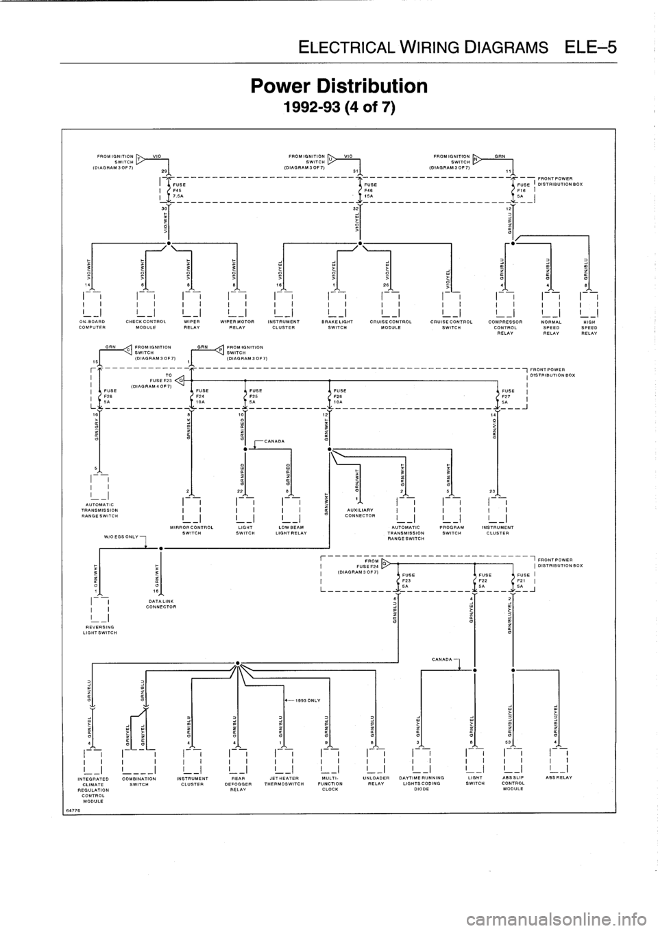
EKE
Power
1992-
VIO
FROMIGNITION
U
VIO
FROM
IGNITI
ON
SWITCH
SWITCH
2S
(DIAGRAM3OF7)
31
(DIAGRAM3OF7)
I
-
______________-__________--
4
-_____________________I_-FRONT
POWER
O
3
3
3
3
i
14
8
8
B
18
7
26
-
4
4
I
i
I
I
i
-F-
I
i
I
-
,
I
,
I
I
F-,
ON
-BOARD
CHECKCONTROL
WIPER
WIPER
MOTOR
INSTRUMENT
BRAKELIGHT
CRUISE
CONTROL
CRUISE
CONTROL
COMPRESSOR
NORMALCOMPUTER
MODULE
RELAYRELAY
CLUSTER
SWITCH
MODULE
SWITCH
CONTROL
SPEEDRELAYRELAY
GRN
0
FROM
IGNITION
GRN
P
FROM
IGNITION
~I
I
VSWITCH
SWITCH
(DIAGRAM
30F7)
,~
(DIAGRAM
3OF7)
-------_-_____________________________________________~FRONT
POWER
TO
I
DISTRIBUTIONBOX
FUSE
F23
G
(DIAG
RAM
4
0F
7)
I
FUSE
FUSE
FUSE
FUSE
FUSE
'
F26
F24
F25
F26
-
F27
6A
10A
SA
ICA
5A
is
S
,0
12
,4
o3
>
CANADA
5
I
~
~
~
3
33
-
2
22
B
F
O
2
5
23
AUTOMATIC
I
I
I
3
1
I
TRANSMISSION
AUXILIARY
RANGESWITCH
I
-
I
I
-
I
I
-
I
CONNECTOR
MIRRORCONTROL
LIGHT
LOWBEAM
AUTOMATIC
PROGRAM
INSTRUMENT
SWITCHSWITCH
LIGHTRELAY
TRANSMISSION
SWITCH
CLUSTER
WIOEGSONLY
RANGESWITCH
FROM
___________-----1FRONTPOWER
FUSEF24
CI
DISTRIBUTION
BC
3
(DIAGRAM30F7)
FUSE
FUSEFUSE
F23
F22
F21
O
O
SA
SA
5A
DATA
LINK
6
j
2
I
CONNECTOR
REVERSING
LIGHTSWITCH
CANADA
O
"
-1993
ONLY
O4
4
4
1
S
B
3
B
53
4
I
v
I~
i
I
i
I
v
I
i
I
v
I
i
I
v
I
i
I
i
I
i
v
v
v
v
~
v
v
~
~
v
v
~
v
v
o
n
v
v
v
v
v
v
_I
INTEGRATED
COMBINATION
INSTRUMENT
REAR
JETHEATER
MULTI-
UNLOADER
DAYTIMERUNNING
LIGHT
ASSSLIP
ABSRELAY
CLIMATE
SWITCH
CLUSTER
DEFOGGER
THERMOSWITCH
FUNCTION
RELAY
LIGHTSCODING
SWITCH
CONTROL
REGULATION
RELAY
CLOCK
DIODE
MODULE
CONTROL
MODULE
64776