airbag off BMW 328i 1995 E36 User Guide
[x] Cancel search | Manufacturer: BMW, Model Year: 1995, Model line: 328i, Model: BMW 328i 1995 E36Pages: 759
Page 387 of 759
610
Electrical
Component
Locations
GENERAL
...........
.
.
.
.
.
.
.
.
.
........
610-1
FOSE
POSITION
TABLES
..
.
.
.
.
.
.....
.
610-19
FUSE
AND
RELAY
POSITIONS
.
...
.
.
.
.
.
610-1
Fuse
Positions
.
.
.
................
.
.
.
.
.
610-1
Relay
Positions
.
.
.
.....
.
.
.
........
.
.
.
.
.
610-2
Auxiliary
RelayPanel
.....
.
...
.
........
.
610-2
SplicePanel,
Left
.
.
.
...
.
.
.
...
.
........
.
610-2
SplicePanel,
Right
.
.
.
.
.
.
.
.
...
.
.........
610-3
COMPONENT
LOCATIONS
.
.
.
.
.......
.
.610-3
Component
Location
Table
.
.
.
.
.
.
.........
610-9
GENERAL
FUSE
AND
RELAY
POSITIONS
This
repair
group
covers
f
use,
relay,
and
control
module
lo-
The
front
power
distribution
box,
an
auxiliary
relay
panel,cation
information
.
Electrical
equipment
and
accessories
in-
and
two
auxiliary
splice
panels
contain
most
of
the
fuses
and
stalled
varies
depending
on
model
and
model
year
.
Always
relays
in
E36
vehicles
.
Refer
to
the
component
location
later
confirm
that
the
proper
electrical
component
has
been
identi-
in
this
section,
as
well
as
the
tables
at
the
end
of
this
repair
fied
by
using
the
electrical
wiring
diagrams
.
group
for
electrical
component
location
.
WARNING
-
On
cars
equipped
with
airbags,
special
precautionsapply
to
any
electrical
system
testing
orrepair
.
Air-
bag
units
areexplosive
devices
and
mustbe
han-
dled
with
extremecare
.
Before
starting
any
work
onan
airbag
equipped
car,
refer
to
the
wamings
and
cautions
in
721
Airbag
System
(SRS)
.
CAUTION
-
"
Prior
to
disconnectiog
the
battery,
read
the
bat-
tery
disconnection
cautions
given
at
the
front
of
this
manual
on
page
viii
.
"
Relay
and
fuse
positions
are
subject
to
changeand
may
varyfrom
car
to
car
.
If
questions
arise,
an
authorized
BMW
dealer
is
the
best
source
for
the
most
accurate
and
up-to-date
information
.
"
A
good
way
to
verify
a
relay
position
isto
com-
pare
the
wiring
colors
at
the
relay
socket
to
thecolors
indicated
on
the
wiring
diagrams
located
at
the
rear
of
this
manual
.
"
Always
switchthe
ignition
off
and
disconnect
the
negative
(-)
battery
cable
before
removing
any
electrical
components
.
"
Connect
and
disconnect
ignition
system
wires,
multiple
connectors,
and
ignition
test
equipment
leads
only
while
the
ignition
is
switched
off
.
"
Only
usea
digital
multimeter
for
electrical
tests
.
ELECTRICAL
COMPONENT
LOCATIONS
610-1
TABLES
a
.
E36Component
Locations
...........
.
.
..
...
610-10b
.
1992
E36
Fuse
Positions
..........
..
.
.
.....
610-20c
.
1993
E36
Fuse
Positions
..........
..
..
.
....
610-22d
.
1994
E36
Fuse
Positions
.........
...
.......
610-24e
.
1995
E36
Fuse
Positions
.........
...
.......
610-26
f
.
1996
E36
Fuse
Positions
.........
...
.......
610-28g
.
1997-1998
E36
Fuse
Positions
..
.
..
...
.......
610-30
Fuse
Positions
CAUTION
-
"
Replace
fuses
with
those
of
the
same
rating
.
In-
stalling
a
fuse
with
higher
rating
can
lead
to
cir-
cuit
failure
and
may
also
start
a
fire
.
"
Relay/fuse
positions
vary
by
model
and
equip-
ment
.
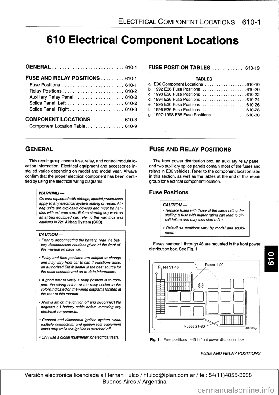
Fuses
number
1
through
46
are
mounted
in
the
front
power
distribution
box
.
See
Fig
.
1.
Fuses
31-46
~
Illlllllllll
°
-
Ilmmlmomlmoi
Fuses
1-20
(a
1
:1
E
El
~
~O!7
L~~n
4~
i
Fuses
21-30
Fig
.1.
Fuse
positions
1-46
in
front
power
distribution
box
.
0013034
FUSE
AND
RELAY
POSITIONS
Page 394 of 759
610-$
ELECTRICAL
COMPONENT
LOCATIONS
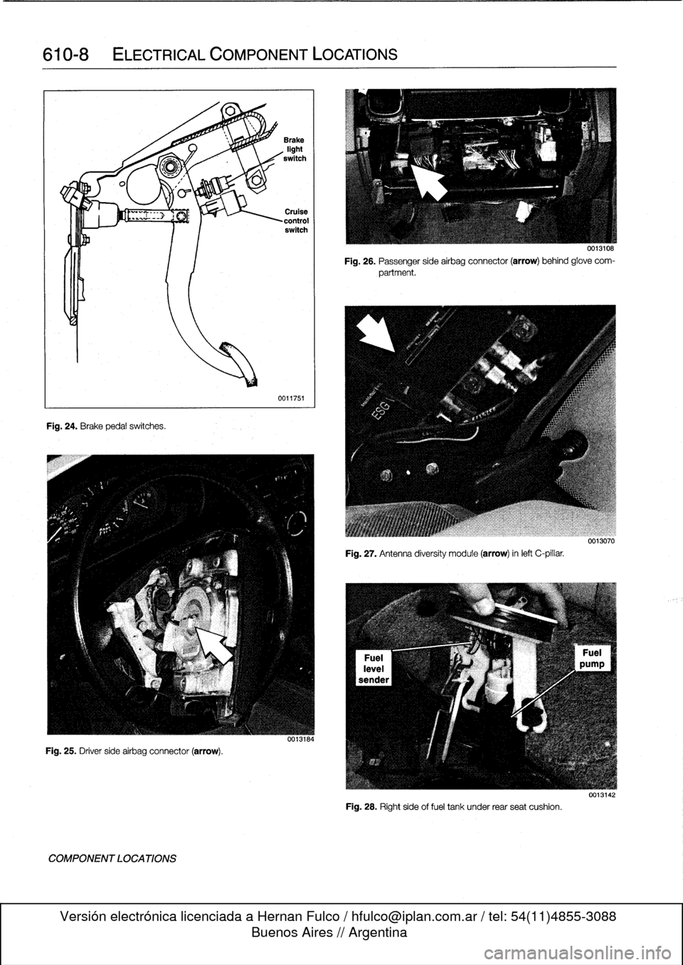
Fig
.
24
.
Brake
pedalswitches
.
Fig
.
25
.
Driver
side
airbag
connector
(arrow)
.
COMPONENT
LOCATIONS
0011751
Fig
.
26
.
Passenger
sideairbag
connector
(arrow)
behind
glove
com-
partment
.
Fig
.
27
.
Antenna
diversity
module
(arrow)
inleft
C-pillar
.
Fig
.
28
.
Right
side
offuel
tank
under
rear
seat
cushion
.
0013108
0013010
0013142
Page 430 of 759
612-2
SWITCHES
AND
ELECTRICAL
ACCESSORIES
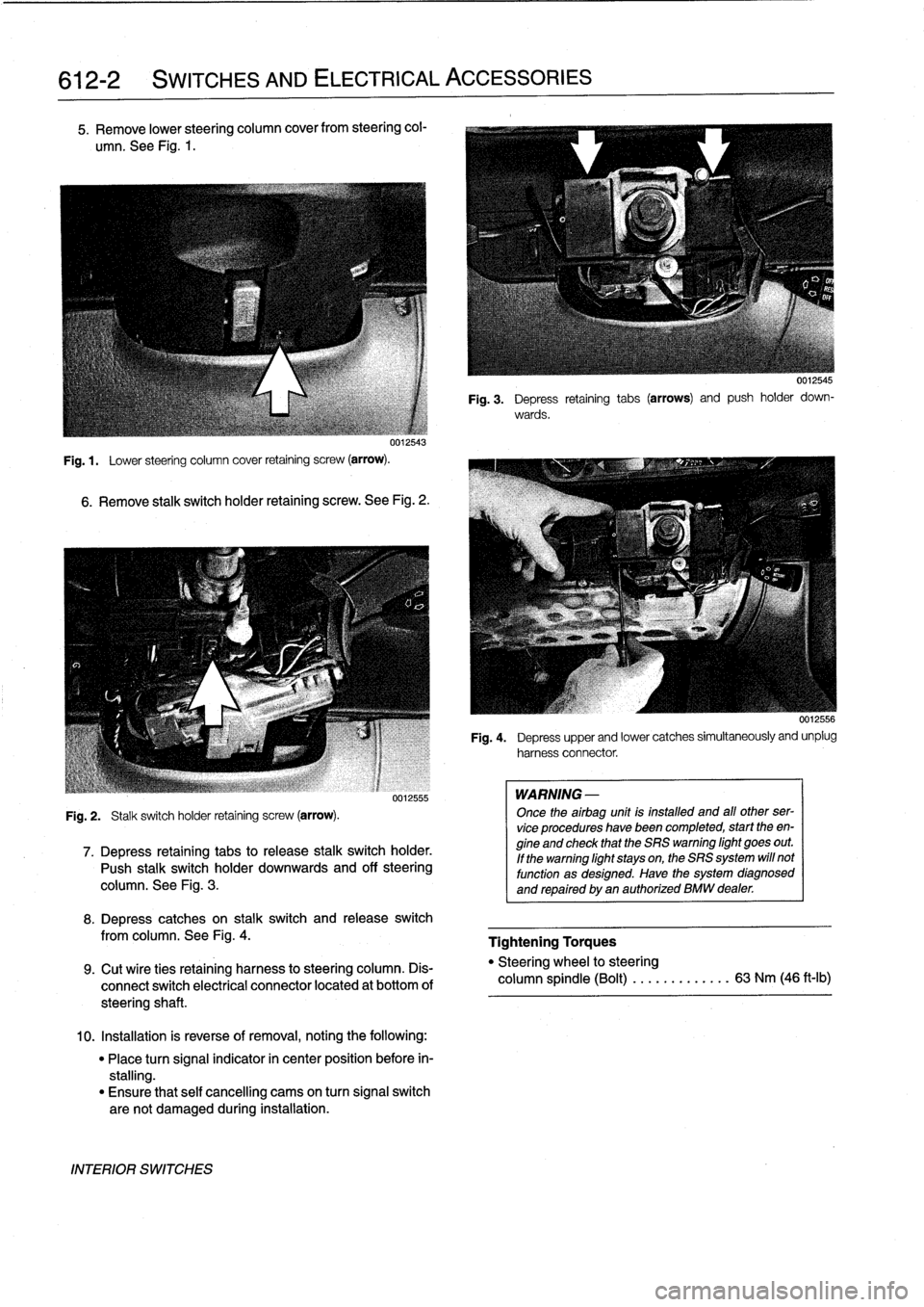
5
.
Remove
lower
steering
column
cover
from
steering
col-
umn
.
See
Fig
.
1
.
uu12543
Fig
.
1
.
Lower
steering
column
cover
retaining
screw
(arrow)
.
6
.
Remove
stalk
switch
holder
retaining
screw
.
See
Fig
.
2
.
Fig
.
2
.
Stalk
switch
holder
retaining
screw
(arrow)
.
0012555
7
.
Depress
retaining
tabs
to
release
stalk
switchholder
.
Push
stalk
switchholder
downwards
and
off
steering
column
.
See
Fig
.
3
.
8
.
Depress
catches
on
stalk
switch
and
release
switch
from
columna
See
Fig
.
4
.
9
.
Cut
wíre
ties
retaining
harness
to
steering
column
.
Dis-
connect
switch
electrical
connector
located
at
bottom
of
steeringshaft
.
10
.
Installation
is
reverse
of
removal,
noting
the
following
:
"
Place
turn
signal
indicator
in
center
position
before
in-
stalling
.
"
Ensure
that
self
cancelling
cams
on
turn
signal
switch
are
not
damaged
during
installation
.
INTERIOR
SWITCHES
WARNING
-
Once
theairbag
unit
is
installed
and
all
other
ser-
vice
procedures
havebeen
completed,
start
theen-
gine
and
check
that
the
SRS
warning
light
goes
out
.
If
the
warning
light
stays
on,
the
SRS
system
will
not
function
as
designed
.
Have
the
system
diagnosed
and
repaired
by
an
authorized
BMW
dealer
.
0012545
Fig
.
3
.
Depress
retaining
tabs
(arrows)
and
push
holder
down-
wards
.
0012556
Fig
.
4
.
Depress
upper
and
lower
catches
simultaneously
and
unplug
harnessconnector
.
Tightening
Torques
"
Steering
wheel
to
steering
column
spindle
(Bolt)
...
.
.
.
..
.....
63
Nm
(46
ft-lb)
Page 437 of 759
INSTRUMENT
CLUSTER
....
.
.
.
.
.
...
.
..
620-1
Instrument
cluster,
seif-testing
.
.
.......
.
..
620-1
Instrument
cluster,
removing
and
installing
...
620-1
Instrument
cluster
bulbs,
replacing
.
.
.
.
.
.
...
620-2
GENERAL
This
repair
group
covers
removal
and
installation
of
the
in-
strument
cluster
and
the
Multi-information
Display
(MID)
mod-
ule
.
Bulb
replacement
information
for
these
units
is
also
included
here
.
NOTE
-
A
quick
check
of
the
temperature
gauge
and
its
electri-
cal
circuitis
given
in
170
Radiator
and
Cooling
Sys-
tem
.
Use
this
procedure
to
diagnosea
faulty
temperature
gauge
INSTRUMENT
CLUSTER
When
servicing
the
instrument
cluster,
always
disconnect
the
negative
(-)
cable
from
the
battery
and
insulate
the
cable
end
to
prevent
accidental
re-connection
.
Instrument
cluster,
seif-testing
Severa¡
different
versions
of
the
basic
instrument
cluster
havebeen
fitted
in
E36
cars
.
It
is
possibleto
perform
an
instru-
ment
cluster
test
and
display
system
test
information
.
Some
of
the
information
displayed
by
the
instrument
cluster
during
seif-testing
is
used
for
interna¡
BMW
organizationpur-
poses,
suchasmatching
the
correct
instrument
cluster
com-
ponents
during
parts
replacement
.
Other
functions
test
the
various
instrument
modules
.
Self-test
is
also
used
to
recode
the
instrument
cluster
after
removal
.
In
later
production
vehicles
(1996
and
later)
the
test
results
canbe
downioaded,
via
the
diagnostic
plug,
byan
authorized
BMW
dealertechnician
.
1
.
Turn
ignition
to
"radio"position
.
2
.
Press
and
hold
reset
button
on
trip-odometer
untiltrip-
odometer
display
shows
numerical
codes
.
620
Instruments
4
.
Turn
off
ignition
.
Instrument
cluster,
removing
and
installing
INSTRUMENTS
620-1
GENERAL
.....
.
.
.
.
.
.
.
.
.
.........
.
....
620-1
Odometer
coding
plug,
replacing
.....
.
.
.
.
.
.
620-2
Vehicle
speed
sender,
replacing
...
.
.
.
.
.
.
.
.
620-3
MULTI-INFORMATION
DISPLAY
(MID)
.
.
.
620-4
Multi-Information
Display,
removing
and
installing
..
.
....
.
.........
620-4
3
.
With
each
subsequent
press
of
the
button,
a
different
function
is
tested
.
Some
functions
will
activate
need1e
gauges
.
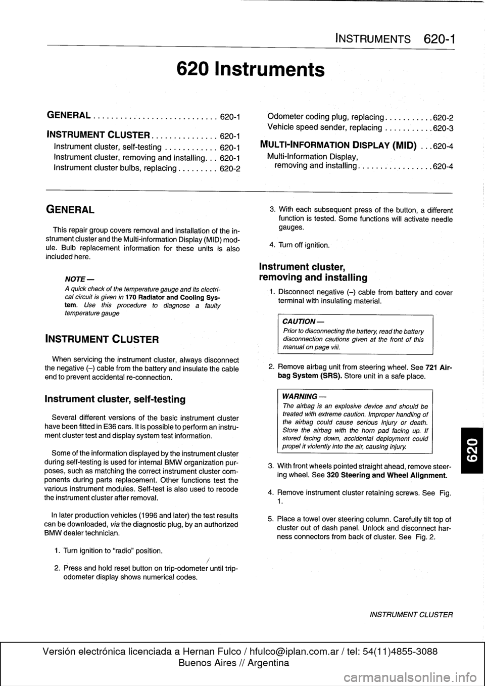
1
.
Disconnect
negative
(-)
cable
from
battery
and
cover
terminal
with
insulating
material
.
CAUTION-
Prior
to
disconnectiog
the
battery,
read
the
battery
disconnection
cautionsgiven
at
the
front
of
this
manual
on
page
vi¡¡
.
2
.
Remove
airbag
unit
from
steering
wheel
.
See
721
Air-
bag
System
(SRS)
.
Store
unit
in
a
safe
place
.
WARNING
-
The
airbag
is
an
explosive
devfce
and
should
be
treated
with
extreme
caution
.
Improper
handling
of
the
airbag
could
cause
serious
injury
or
death
.
Store
the
airbag
with
the
horn
pad
facing
up
.
If
stored
facing
down,
accidental
deployment
couldpropel
it
vfolently
into
the
air,
causing
injury
.
3
.
With
front
wheels
pointed
straight
ahead,
remove
steer-
ing
wheel
.
See
320
Steering
and
Wheel
Alignment
.
4
.
Remove
instrument
cluster
retaining
screws
.
See
Fig
.
1
.
5
.
Place
a
towel
over
steering
column
.
Carefully
tilt
top
of
cluster
out
of
dash
panel
.
Unlock
and
disconnect
har-
ness
connectors
from
back
of
cluster
.
See
Fig
.
2
.
INSTRUMENT
CLUSTER
Page 469 of 759
Rear
speaker,
removing
and
installing
Door
panel
speaker,
removing
and
installing
NOTE
-
Rear
speakers
in
convertible
models
are
installed
un-
der
the
rear
side
panels
.
For
rearside
panelremoval
procedure,
see
411Doors
.
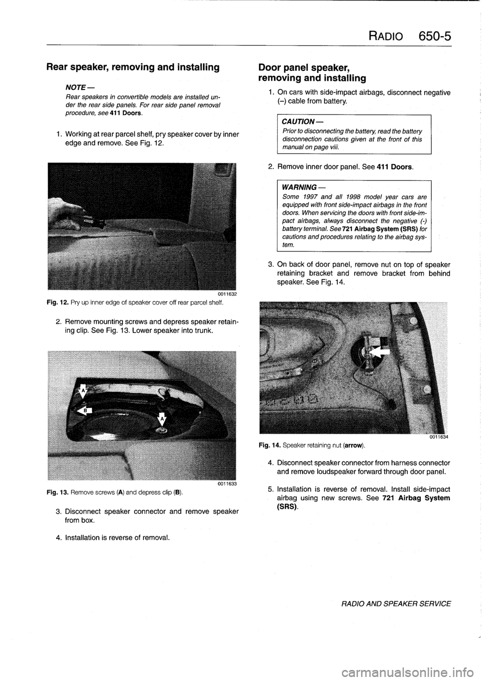
1
.
Working
at
rear
parcel
shelf,
pry
speakercoverby
inner
edge
and
remove
.
See
Fig
.
12
.
0011632
Fig
.
12
.
Pry
up
inner
edge
of
speaker
cover
off
rear
parcel
shelf
.
2
.
Remove
mountingscrews
and
depress
speaker
retain-
ing
clip
.
See
Fig
.
13
.
Lower
speaker
into
trunk
.
Fig
.
13
.
Remove
screws
(A)
and
depress
clip
(B)
.
4
.
Installation
is
reverse
of
removal
.
0011633
3
.
Disconnect
speaker
connector
andremove
speaker
from
box
.
RAM
650-5
1.
On
carswith
side-impact
airbags,
disconnect
negative
(-)
cable
from
battery
.
CAUTION-
Prior
to
disconnecttog
the
battery,
read
the
battery
disconnection
cautions
given
at
the
front
of
this
manual
on
page
vi¡¡
.
2
.
Remove
inner
door
panel
.
See
411
Doors
.
WARNING
-
Some
1997
and
all
1998
model
year
cars
are
equipped
with
front
side-impact
airbags
in
the
front
doors
.
When
servicing
the
doors
with
front
side-im-
pact
airbags,
alwaysdisconnect
the
negative
()
battery
terminal
.
See
721Airbag
System
(SRS)
for
cautions
and
procedures
relating
to
theairbag
sys-
tem
.
3
.
On
back
of
door
panel,
remove
nut
on
top
of
speaker
retaining
bracket
and
remove
bracket
from
behind
speaker
.
See
Fig
.
14
.
Fig
.
14
.
Speaker
retaining
nut
(arrow)
.
4
.
Disconnect
speaker
connector
from
harness
connector
and
remove
loudspeaker
forwardthrough
door
panel
.
5
.
Installation
is
reverse
of
removal
.
Install
side-impact
airbag
using
new
screws
.
See
721
Airbag
System
(SRS)
.
RADIO
AND
SPEAKER
SERVICE
Page 477 of 759
721
Airbag
System
(SRS)
Airbag
Systems
.......
.
...
.
.
.
.
.
....
.
.
.
.
721-1
AIRBAG
SENSORS
AND
ELECTRONICS
721-2
SRS
Warning
Light
and
Fault
Display
.
.
.
.
.
..
721-2
Airbagcontact
ring,
replacing
........
.
.
.
.
.
721-3
Airbag
crash
sensor,replacing
..
.
....
.
...
.
721-4
ZAE
control
module,
replacing
.
.
.
.........
721-5
GENERAL
This
repair
group
covers
only
removal
and
installation
of
air-
bag
components
.
Airbag
system
repair
and
fault
diagnosis
is
not
covered
here
.
Diagnostics,
component
testing,
and
airbag
system
repair
should
be
carried
out
by
trained
BMW
service
technicians
.
NOTE-
Special
test
equipment
is
required
to
retrieve
SRS
fault
codes,
diagnose
system
faults,
and
resetltum
off
the
SRS
indicator
light
.
The
SRS
indicator
light
will
remain
on
until
any
problem
has
been
corrected
and
the
fault
memory
has
been
cleared
.
When
servicing
cars
equipped
with
SRS,
the
precautions
on
this
page
mustbeobserved
to
prevent
personal
injury
.
Airbag
Systems
The
airbag
system
installed
on
E36
cars
through
the
1993
model
year
consisted
of
a
single
airbag
in
the
steering
wheel
.
This
systemcan
be
identified
by
the
orange
crash
sensors
lo-
cated
on
the
front
wheel
wells
and
the
absence
of
a
passenger
side
airbag
.
The
ZAE
airbag
system,
starting
in
model
year
1994
(pro-
duction
date9/93
and
later),
provides
both
a
driver
side
and
a
passenger
sideairbag
.
On
ZAE
vehicles,
the
crash
sensorsare
integrated
into
the
airbag
control
module,
located
under
thecenter
of
the
rear
seat
.
The
ZAE
control
module
triggers
deployment
of
the
airbags
When
it
sensos
the
vehicle
deceler-
ating
at
a
rate
equivalent
to
a
head-on
collisionof
at
least
13
mph
(18
km/h)
.
In
some
1997
4-door
models
and
all
1998
models,
side-impact
airbags
were
installed
in
the
front
doors
.
The
airbag
units
are
mounted
behindthe
door
trim
panels
.
Caution
mustbeused
when
working
on
vehicle
systems
in
the
proximity
of
air
bags,
such
as
the
steering
column,
the
dashboard,
or
the
doors
.
AIRBAG
SYSTEM
(SRS)
721-1
GENERAL
.
.
.
.
.
.
.
.
.
.
.......
.
......
.
.
.
.
721-1
Front
side-impact
airbag
crash
sensor,
removing
and
installing
....
.
.....
.
.....
.
721-5
AIRBAGS
..............
.
.
.
.
.
.
.
.
.
.
.
.
.
.
.
721-5
Driver
side
airbag,
removing
and
installing
.
.
.
721-5
Passenger
side
airbag,
removing
and
installing
..............
.
.
.721-6
Front
side-impact
airbag,
removing
and
installing
.
.
.
.
.
.
.
.
.
.
......
.721-7
WARNING
-
"
Airbag(s)
are
inflated
byan
explosive
device
.
Handled
improperly
or
without
adequate
safe-
guards,
the
System
can
be
very
dangerous
.
Spe-
cial
precautions
must
be
observed
prior
to
any
work
ator
near
the
driverside
airbag,
the
passen-
ger
side
airbag
(where
applicable)
or
the
side-im-
pact
airbags
(where
applicable)
.
"
The
airbag
is
a
vehicle
safety
system
.
Serious
in-
jury
may
result
if
System
service
is
attempted
by
persons
unfamiliar
with
the
BMW
SRS
and
its
ap-
proved
service
procedures
.
BMW
advises
that
all
inspection
and
service
be
performed
by
an
autho-
rized
BMW
dealer
.
"
Always
disconnect
the
battery
and
cover
the
neg-
ative
()
battery
terminal
with
an
insulator
before
startingdiagnostic,
troubleshooting
or
service
worknot
associated
with
SRS,
and
before
doing
any
welding
on
the
car
.
"
If
an
airbag
has
been
activated
due
to
an
acci-dent,
BMW
specifies
that
SRS
components
be
replaced
.
For
more
information
on
post-collision
SRS
service,
see
an
authorized
BMW
dealer
.
"
Do
not
allow
the
airbag
unit
to
come
in
contact
with
cleaning
solutions
orgrease
.
Never
subject
an
airbag
unit
to
temperatures
aboye
212°F
(100°C)
.
When
reconnecting
the
battery,
no
per-
son
should
be
inside
the
vehicle
.
"
Always
place
an
airbag
unitthat
has
been
re-
moved
from
its
packaging
with
the
padded
sidefacing
upward
.
Do
not
leave
an
airbag
unlt
unat-
tended
.
"
!f
the
airbag
unit
or
airbag
control
modulehas
been
dropped
froma
height
of
!
1
2
meter
(1
Y2
ft.)
ormore,
theairbag
unit
should
not
be
installed
.
Aírbag
system
components
are
shown
in
Fig
.
1.
GENERAL
Page 481 of 759
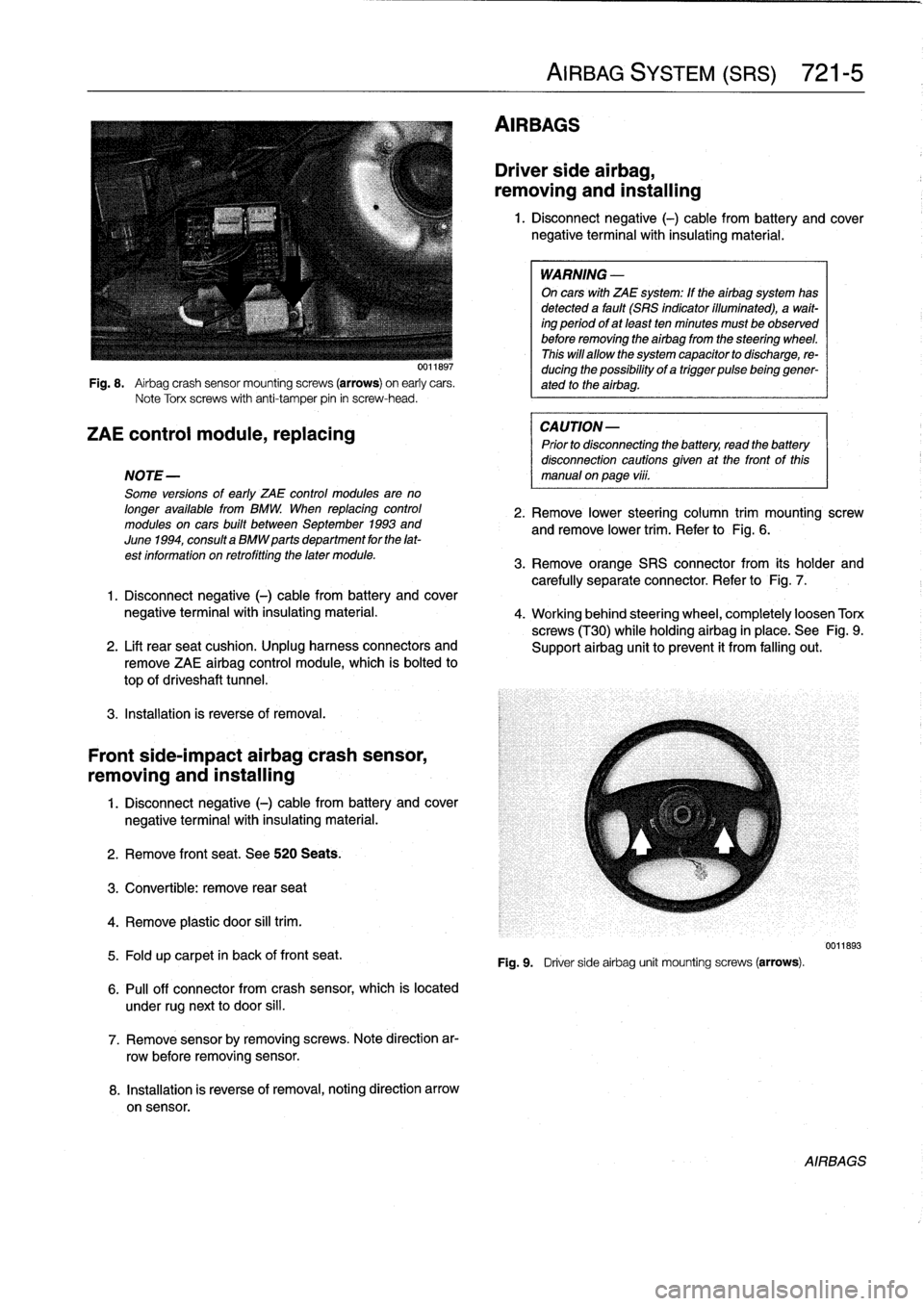
Fig
.
8
.
Airbag
crash
sensor
mountingscrews
(arrows)
on
early
cars
.
Note
Torx
screws
with
anti-tamper
pin
in
screw-head
.
ZAE
control
module,
replacing
NOTE-
Some
versions
of
early
ZAE
control
modules
are
no
longer
available
from
BMW
.
When
replacing
control
modules
on
cars
built
between
September
1993
and
June
1994,
consulta
BMW
parts
department
for
the
lat-
est
information
on
retrofitting
the
later
module
.
3
.
Remove
orange
SRS
connector
from
its
holder
and
carefully
separate
connector
.
Refer
to
Fig
.
7
.
1
.
Disconnect
negative
(-)
cable
from
battery
and
cover
negative
terminalwith
insulating
material
.
4
.
Working
behind
steering
wheel,
completely
loosen
Torx
screws
(T30)
while
holdingairbag
in
place
.
See
Fig
.
9
.
2
.
Lift
rearseat
cushion
.
Unplug
harness
connectors
and
Support
airbag
unit
toprevent
it
from
falling
out
.
remove
ZAE
airbag
control
module,
which
is
bolted
to
top
of
driveshaft
tunnel
.
3
.
Installation
is
reverse
of
removal
.
Front
side-impact
airbag
crash
sensor,
removing
and
installing
1
.
Disconnect
negative
(-)
cable
from
battery
and
cover
negative
terminal
with
insulating
material
.
2
.
Remove
front
seat
.
See520
Seats
.
3
.
Convertible
:
remove
rear
seat
4
.
Remove
plastic
door
sill
trim
.
5
.
Fold
up
carpet
in
back
of
front
seat
.
6
.
Pull
off
connector
from
crash
sensor,
which
is
located
under
rugnext
to
door
si¡¡
.
7
.
Remove
sensorby
removing
screws
.
Note
direction
ar-
row
before
removing
sensor
.
8
.
Installation
is
reverse
of
removal,noting
direction
arrow
on
sensor
.
AIRBAGS
AIRBAG
SYSTEM
(SRS)
721-
5
Driver
side
airbag,
removing
and
installing
1
.
Disconnect
negative
(-)
cable
from
battery
and
cover
negative
terminal
with
insulating
material
.
WARNING
-
On
cars
with
ZAE
system
:
If
theairbag
system
has
detected
a
fault
(SRS
indicator
illuminated),
a
wait-
ing
period
ofat
least
ten
minutes
must
be
observed
before
removing
the
airbag
from
the
steering
wheel
.
This
will
allow
the
system
capacitor
to
discharge,
re-
ducing
the
possibility
of
a
trigger
pulsebeinggener-
ated
to
the
airbag
.
CAUTION-
Prior
to
disconnecting
the
battery,
read
the
battery
disconnection
cautions
given
at
the
front
of
this
manual
on
page
vi¡¡
.
2
.
Remove
lower
steering
column
trim
mounting
screw
andremove
lower
trim
.
Refer
to
Fig
.
6
.
Fig
.
9
.
Driver
sideairbag
unit
mounting
screws
(arrows)
.
0011893
AIRBAGS
Page 482 of 759
721-
6
AIRBAG
SYSTEM
(SRS)
5
.
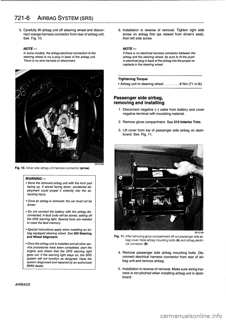
Carefully
lift
airbag
unit
off
steering
wheel
and
discon-
6
.
Installation
is
reverse
of
removal
.
Tighten
right
side
nect
orange
harness
connector
from
rear
of
airbag
unit
.
screw
on
airbag
first
(as
viewedfrom
driver's
seat),
See
Fig
.
10
.
then
left
side
screw
.
NOTE-
NOTE-
In
some
models,
theairbag
electrical
connection
to
the
If
there
is
no
electrical
harness
connector
between
the
steering
wheel
isvia
aplug
in
back
of
the
airbag
unit
.
airbag
and
the
steering
wheel,
be
sure
to
fit
the
push
There
is
no
wire
harness
to
disconnect
.
in
electrical
plug
in
back
of
the
airbag
finto
the
proper
re-
ceptacle
in
the
steering
wheel
.
Fig
.
10
.
Driver
sideairbag
unit
harness
connector
(arrow)
.
AIRBAGS
WARNING
-
"
Store
the
removed
airbag
unit
with
the
horn
pad
facing
up
.
If
stored
facing
down,
accidental
de-
ployment
couldpropel
it
violently
into
the
air,
causing
injury
.
"
Once
an
airbag
is
removed,
the
car
must
not
be
driven
.
"
Do
not
connect
the
battery
with
the
airbag
dis-
connected
.
A
fault
code
will
be
stored,
setting
off
the
SRS
warning
light
.
Special
tools
are
needed
to
reset
the
fault
memory
.
"
Special
instructions
apply
when
installing
an
air-
bag
equipped
steering
wheel
.
See
320
Steering
and
Wheel
Alignment
.
"
Once
the
airbag
unit
is
installnd
and
all
other
ser-vice
procedureshave
been
completed,
start
the
engíne
and
check
that
the
SRS
warning
light
goes
out
.
If
the
warning
light
stays
on,
the
SRS
system
will
not
function
as
designed
.
Have
the
system
diagnosed
and
repaired
by
an
authorized
BMW
dealer
.
0013184
Tightening
Torque
"
Airbag
unitto
steering
wheel
........
8
Nm
(71
in-lb)
Passenger
side
airbag,
removing
and
installing
1
.
Disconnect
negative
(-)
cable
from
battery
and
cover
negative
terminal
with
insulating
material
.
2
.
Remove
glove
compartment
.
See
513
Interior
Trim
.
3
.
Lift
cover
from
topof
passenger
sideairbag
on
dash-
board
.
See
Fig
.
11
.
0013108
Fig
.
11
.
After
removing
glove
compartment,
lift
out
passenger
side
air-
bag
cover
.
Note
airbag
mounting
bolts
(A)
and
airbag
electri-
cal
connector
(B)
.
4
.
Remove
passenger
sideairbag
mounting
bolts
.
Dis-
connect
electrical
harness
connector
from
rear
of
air-
bag
unit
and
remove
airbag
.
5
.
Installation
is
reverse
of
removal
.
Make
sure
wiring
har-
ness
is
not
pínched
when
installing
airbag
unit
in
dash-board
.
Page 485 of 759
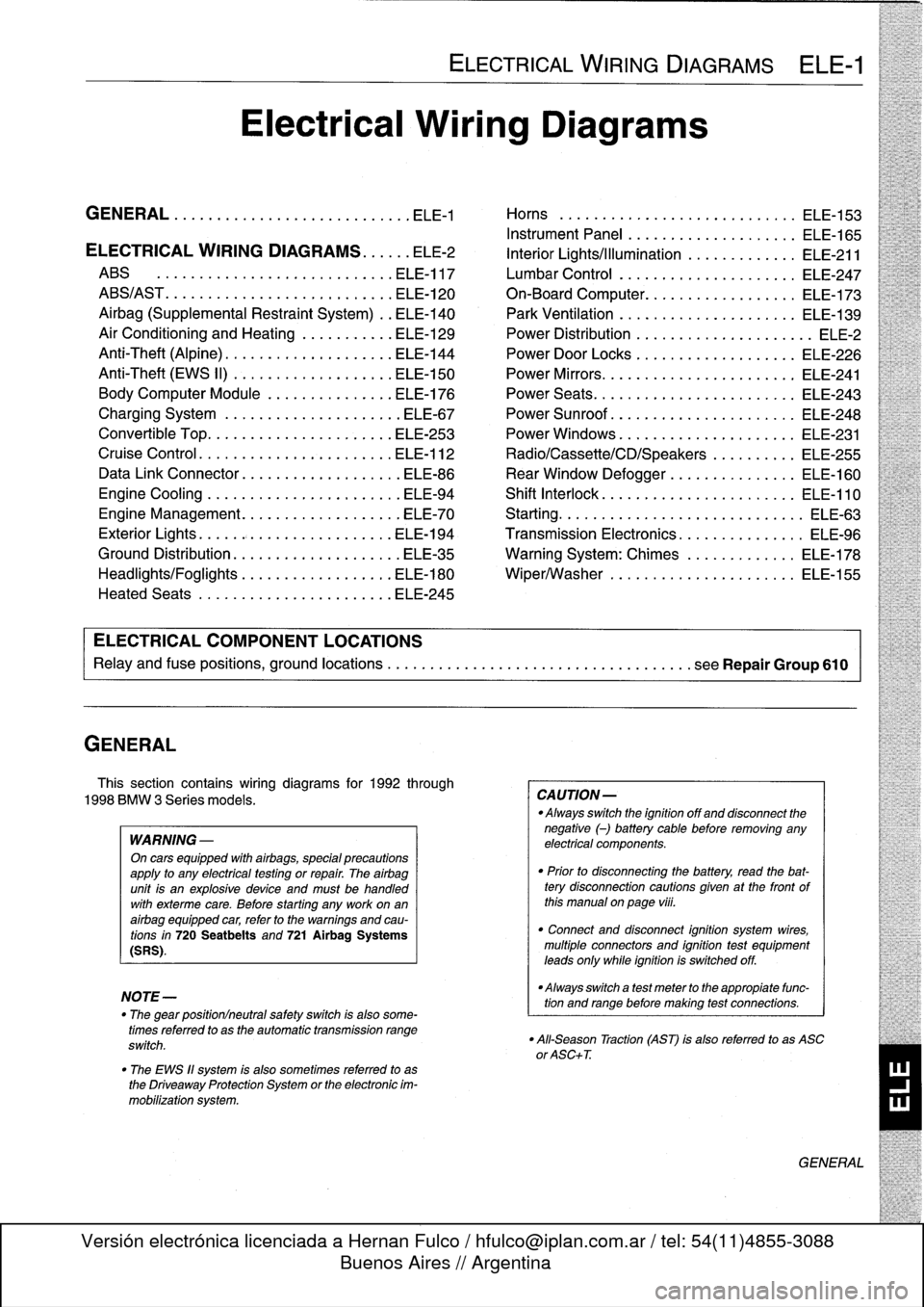
GENERAL
This
section
contains
wiring
diagrams
for
1992
through
1998
BMW
3
Series
models
.
WARNING
-
On
cars
equipped
with
airbags,
special
precautions
apply
to
any
electrical
testing
or
repair
.
The
airbag
unit
is
an
explosive
device
and
must
be
handled
with
exterme
care
.
Before
starting
any
work
onan
airbag
equipped
car,
refer
to
the
warnings
and
cau-
tions
in
720
Seatbelts
and
721
Airbag
Systems
(SRS)
.
NOTE-
The
"
gear
position/neutral
safetyswitch
is
also
some-
timesreferred
to
as
the
automatic
transmission
range
switch
.
"
The
EWS
11
system
is
also
sometimes
referred
to
as
the
Driveaway
Protection
System
or
the
electronic
im-
mobilization
system
.
ELECTRICAL
WIRING
DIAGRAMS
ELE-1
Electrical
Wiring
Diagrams
GENERAL
.
.
.
.
.
.
.
.
.
................
.
.
.
ELE-1
Horns
.....
.
.....
.
.
.
....
.
.
.
.
.
...
.
.
ELE-153
Instrument
Panel
.
.
.
.
.
.
..............
ELE-165
ELECTRICAL
WIRING
DIAGRAMS
...
.
.
.
ELE-2
Interior
Lights/Illumination
.............
ELE-211
ABS
..............
.
.
.
.....
.
.....
ELE-117
Lumbar
Control
.
....................
ELE-247
ABS/AST
.............
.
.
.
...
.
.
.
.....
ELE-120
On-Board
Computer
..................
ELE-173
Airbag
(Supplemental
Restraint
System)
..
ELE-140
Park
Ventilation
.
.
.
...........
.
...
.
..
ELE-139
Air
Conditioning
and
Heating
.
.
.
.
.
.
.....
ELE-129
Power
Distribution
......
.
...
.
.
.
.
.
.
.
...
.
ELE-2
Anti-Theft
(Alpine)
..........
.
.
.
...
.
...
ELE-144
Power
Door
Locks
.
.
......
.
.
.
.
.
.
.
.
.
..
ELE-226
Anti-Theft
(EWS
II)
.
........
.
.
.
...
.
...
ELE-150
Power
Mirrors
...
.
.
.
......
.
.
.
.
.
.
.
.
.
..
ELE-241
Body
Computer
Module
.....
.
.....
.
...
ELE-176
Power
Seats
......
.
......
.
.
.
...
.
.
.
..
ELE-243
Charging
System
.
.
................
.
.
.
ELE-67
Power
Sunroof
.
.
.
.
.
.
.
...............
ELE-248
Convertible
Top
.
.
.
.
................
.
.
ELE-253
Power
Windows
.
.
.
.
.
.
.....
.
.........
ELE-231
Cruise
Control
..
.
.
.
...........
.
....
.
.
ELE-112
Radio/Cassette/CD/Speakers
..........
ELE-255
Data
Link
Connector
................
.
.
.
ELE-86
Rear
Window
Defogger
...............
ELE-160
Engine
Cooling
.......
.
.......
.
....
.
.
.
ELE-94
Shift
Interlock
.
.
.
.
.
.
.
.
...............
ELE-110
Engine
Management
...
.
.......
.
....
.
.
.
ELE-70
Starting
....
.
.
.
.
.
...
.
................
ELE-63
Exterior
Lights
........
.
.
.
.
.
.
.
.
.
......
ELE-194
Transmission
Electronics
.
..............
ELE-96
Ground
Distribution
....
.
.
.
.
.
.
.
.
.
.......
ELE-35
Warning
System
:
Chimes
.............
ELE-178
Headlights/Foglights
...
.
.
.
.
.
.
.
.
.
......
ELE-180
Wiper/Washer
.
.....
.
...............
ELE-155
Heated
Seats
........
.
.
.
.
.
.
.
.
.
......
ELE-245
ELECTRICAL
COMPONENT
LOCATIONS
Relayand
fuse
positions,
ground
locations
...........
.
.
.
.
.
.
.
.
.
................
seeRepair
Group
610
CAUTION-
Always
switchthe
ignition
off
and
disconnect
the
negative
(-)
battery
cablebefore
removing
any
electrical
components
.
"
Prior
to
disconnecting
the
battery,
read
the
bat-tery
disconnection
cautions
given
at
the
front
of
this
manual
on
page
viii
.
"
Connect
and
disconnect
ignition
system
wires,
multiple
connectors
and
ignition
test
equipment
leads
only
while
ignition
is
switched
off
.
-Always
switch
a
test
meter
to
the
appropiate
func-
tion
and
range
before
making
test
connections
.
"
All-Season
Traction
(AST)
is
also
referred
to
as
ASC
or
ASC+T
.
GENERAL
Page 623 of 759
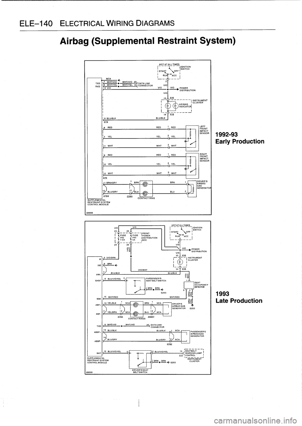
ELE-140
ELECTRICAL
WIRING
DIAGRAMS
Airbag
(Supplemental
Restraint
System)
88996
_HO_T
_AT
ALL
TIMES
IGNITION
SWITCH
!START
START
OFF
NCA
1Ru1~T
-
ACC
_(
7
WHT1110
AI,
I
WHT1VI0
20,
22
T%D
~
"
~~
DATA
LINK
XD
B
"
WHT
EL
1
CONNECTOR
VIO
12
VIO
VIO
VIO
POWER
"
-
i
DISTRIBUTION
VIOI
ABF-
15
~~
.
X-14-
1~
-----
I
INS
I
CR
T
IF
.1ENT
NDICTO~
I1
14T=
`9
BLU
/BLK
BLU/BLK
X74
8
RED
RED
'E
RED
17
VEL
YEL
2
YE-
1
11
WHT
WHT
3
WHT
I
9
RED
RED
1
RED
110
YEL
YEL
?,
YEL
LIT
It
I
VIO/WHT
14
I
X16
AWL
7
BLU/BLK
BLU/BLK
8
BLU11
IO
/VEL
3
PASSENGER'S
>3
GKBF
~~
f7
T
CH
1
1
BRNBRN
~DETECTOR
OY
58E
j
15
WHT/RED
WHT/RED
I
m0
e
,BF+
10
YEL/BLK
1
NCA
BRN
1
7
-
N
-
CA
~~
DRIVER'S
m
i
11
1OE
R
NERATOR
G203
E
TXD
)
9
WWHT/VIO
"
ABBF+
13
BLU/BLK
1
J
BLU/GRV
ABBF-
I
~-
12
XZ83
Xanz
CONTACT
RINGS
WHTIVIO
GKF
12
BLU/VIO/YEL
3
SUPPLEMENTAL
RESTRAINTSVSTEM
CONTROLMODULE
DRIVER'SSEAT
8900D
BELTSWITCH
NC
20
DATALINK
CONNECTOR
BLU/BL
BLUIG
X782
BLU/VIO/VEL
18RN
BRN
"
-#
G203
HOTATALLTIMES
(IGNITION
START
OFFSWITCH
I
I
I
I
RUN
ACC
__I
POWER
V15
IOJ
DISTRIBUTION
XLB
INSTRUMENT
CLUSTER
C
RIGHT
FRONT
IMPACT
SENSOR
DRIVER'S
AIRBAG
GASGENERATOR
PASSENGER'S
AIRBAG
GASGENERATOR
14
~SEATBELT
WARNING
LAMP
XIZICONTROL
INSTRUMENTCLUSTER
LEFT
FRONT
IMPACT
SENSOR
11992-93
Early
Production
1993
Late
Production