catalytic converter BMW 328i 1995 E36 User Guide
[x] Cancel search | Manufacturer: BMW, Model Year: 1995, Model line: 328i, Model: BMW 328i 1995 E36Pages: 759
Page 438 of 759

620-2
INSTRUMENTS
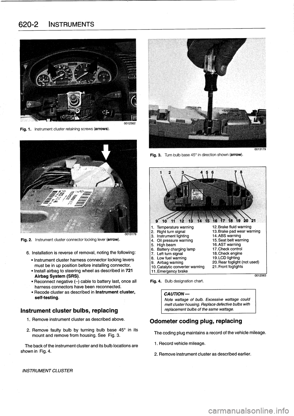
Fig
.1.
Instrument
cluster
retaining
screws
(arrows)
.
INSTRUMENT
CLUSTER
0012562
Fig
.
3
.
Turnbulb
base
45°
in
direction
shown
(arrow)
.
l
v
w
r
v
9
10
11
12
13
14
15
16
)7
18
19
20
y
21
1
.
Temperature
warning
12
.
Brake
fluid
warning
oo13n6
2
.
Right
turn
signal
13
.
Brake
pad
wear
warning
3
.
Instrument
lighting
14
.ABS
warning
Fig
.
2
.
Instrument
cluster
connector
locking
lever
(arrow)
.
4
.
Oil
pressure
warning
15
.
Seat
belt
warning5
.
Highbeam
16
.ASTwarning
6
.
Battery
charging
lamp
17
.Check
control
6
.
Installation
is
reverse
of
removal,
noting
the
following
:
7
.
Left
turn
signal
18
.Check
engine
"
Instrument
cluster
harness
connector
locking
levers
8
.
Low
fuel
warning
19
.
LCD
lighting
must
be
in
up
position
before
installing
connector
.
9
.
Airbag
warning
20
.
Rear
foglight
(not
used)
10
.
Catalytic
converter
warning
21
.
Front
foglights
"
Install
airbag
to
steering
wheel
as
described
in
721
11
.
Emergency
brake
Airbag
System
(SRS)
.
0012563
"
Reconnect
negative
(-)
cable
to
battery
last,
once
al¡
Fig
.
4
.
Bulb
designation
chart
.
harness
connectors
have
been
reconnected
.
"
Recode
cluster
as
described
in
Instrument
cluster,
CAUTION-
seif-testing
.
Note
wattage
of
bulb
.
Excessive
wattage
could
melt
cluster
housing
.
Replace
defective
bulbs
with
Instrument
cluster
bulbs,
replacing
reptacementbulbs
of
the
same
wattage
.
1
.
Remove
instrument
cluster
as
described
above
.
Odometer
coding
plug,
replacing
2
.
Remove
faulty
bulb
by
turning
bulb
base
45°
inits
mount
and
remove
from
housing
.
See
Fig
.
3
.
The
coding
plug
maintains
a
record
of
thevehicle
mileage
.
The
back
of
the
instrument
cluster
and
its
bulb
locations
are
1
.
Record
vehicle
mileage
.
shown
in
Fig
.
4
.
2
.
Remove
instrument
cluster
as
described
earlier
.
Page 563 of 759

GRN/VIO
HOT
IN
RUNAND
START
HOT
FILM
AIR
HALLEFFECT
CRANKSHAFT
ELCTRONIC
r
-1FRONT
MASSMETER
CAMSHAFTSENSOR
POSITION/RPM
IMMOBILIZERCONTROL
I
(POWER
r
-
-
1
1
1
SENSOR
MODULE
(EWS11)
FUSE
I
FSSE
F
IDIS7RIBUTION
I
iDA
ISA
(BOX
I
I
(199fi)
(1997)
I
is
Y
iBy
$
1D01B
I
D
-
22
OXYGENSENSOR
(BEHIND
CATALYTIC
CONVERTER)
88648
FUEL
PUMP
SPLICE
BLK
-----
.--_
.-------
OXYGENSENSOR
(FRONT
OFCATALYTIC
CONVERTER)
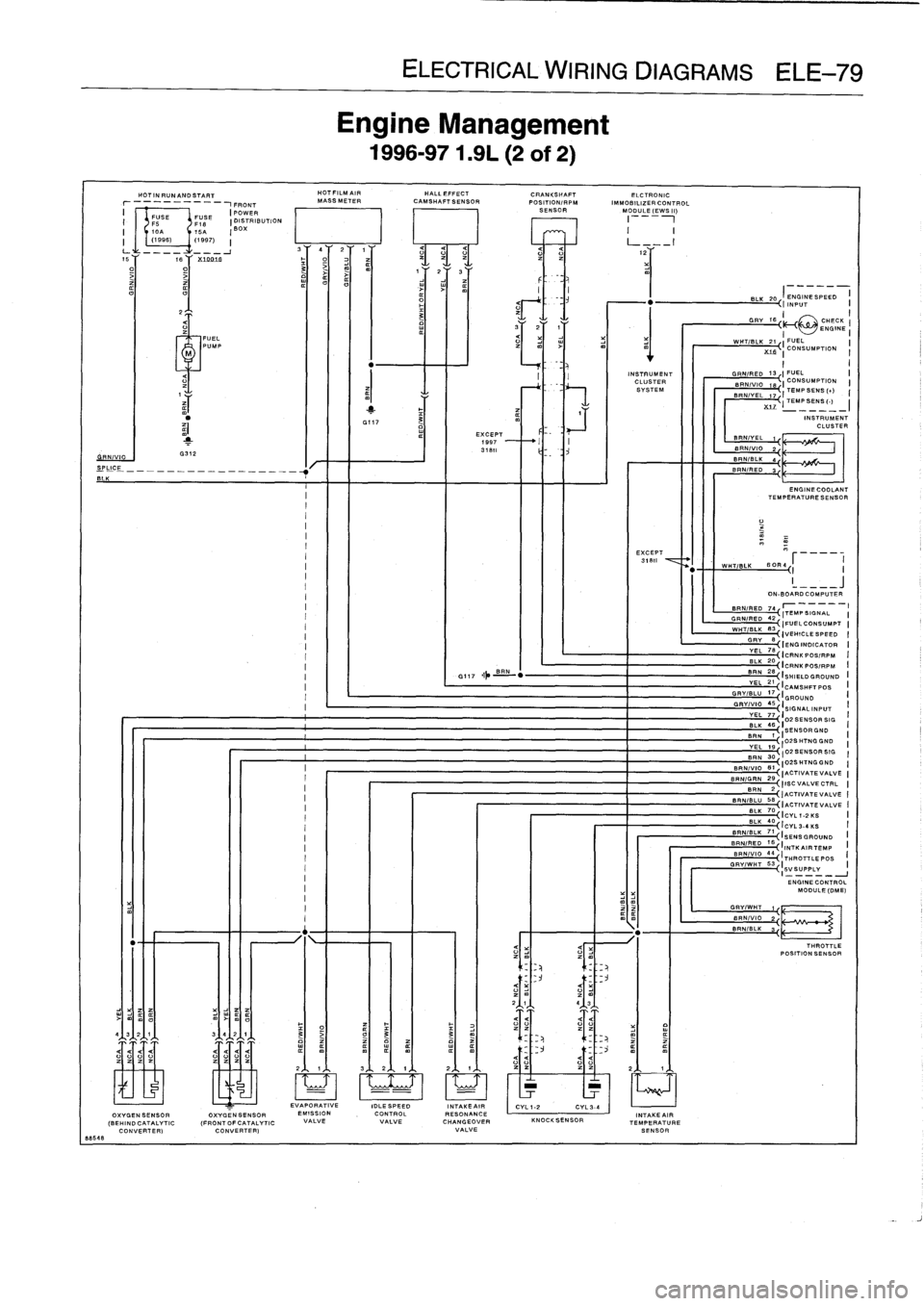
Engine
Management
1996-971
.91-(2
of
2)
EVAPORATIVE
IDLESPEED
EMISSION
CONTROL
VALVEVALVE
ELECTRICAL
WIRING
DIAGRAMS
ELE-79
EXCEPT
1997
318
ti
INSTRUMENT
CLUSTER
SYSTEM
EXCEPT
31811
INTAKEAIR
I
CYL1-2
CYL3-4
RESONANCE
INTAKEAIR
CHANGEOVERKNOCKSENSORTEMPERATURE
VALVE
SENSOR
BLK
IENGINESPEED
I
-
2
k
I
INPUT
I
GRG=1fi~
CHECK
ENGINE
I
WHT/BLK
21
I
FUEL
X
t
fi
'C
CONSUMPTION
I
~GRN/RED
13
3
I
FUEL
I
CONSUMPTION
SRN/VI
jg
TEMPSENS
(L)
BRN/V=L
17{iTEMPSENS(-)
INSTRUMENT
CLUSTER
ENGINECOOLANT
TEMPERATURESENSOR
WW=TIBLK
BOR4
(I
I
__J
ON-BOARD
COMPUTER
BRN/RED
74,
r
_
----
I
~ITEMPSIGNAL
I
-
~GRN/RED
42
J
~IFUELCONSUMPT
I
WHT/BLK
83
~~
I
VEHICLE
SPEED
I
GRV
S,
IENGINDICATOR
I
VEL
78
-
-~{ICRNKPOS/RPM
_ILL
-(ICRNKPOSIRPM
BRN
(SHIELD
GROUND
YEL
I21
CAMSHFTPOS
GRV/BLU
17
'GROUND
GRV/V
-
10
4S
`
VEL77,
:SIGNAL
8-{
I02
SENSOR
SIG
B-
:
..
.SORGND
OISHTNGGND
VEL
19
I
B
3D~I023ENSORBIG
02SHTNGGND
BRN/VIO
B7
I
{
ACTIVATEVALVE
-
-
~BRNIG
RN29
J
I
~
I
ISC
VALVE
CTRL
BRN
2
BRNIBLU~JACTIVATE
VALVE
BIACTIVATEVALVE
-
BILK
70
'
~
BLK
40
;CVL
1-2KS
-~{
I
CYL
3-6
KS
BRN/BLK
711
SENSGROUND
BRN/RED
~
IINTKAIRTEMP
BRN/VIO
44
I
I
~
W
L~~~
THROTTLEPOS
GRVRY/
-
W
I
SVSUPPLY
I
ENGINECONTROL
MODULE
(DME)
THROTTLE
POSITION
SENSOR