fuel filter BMW 328i 1995 E36 User Guide
[x] Cancel search | Manufacturer: BMW, Model Year: 1995, Model line: 328i, Model: BMW 328i 1995 E36Pages: 759
Page 76 of 759
113-10
CYLINDER
HEAD
REMOVAL
AND
INSTALLATION
Tightening
Torques
"
Coolant
drain
plug
to
cylinder
block
.
.
25
Nm
(18
ft-1b)
"
Intake
manifold
support
to
manifold
.
.
15
Nm
(11
ft-Ib)
"
Lower
intake
manifold
to
cylinder
head
.
..........
.
..
...
15
Nm
(11
ft-Ib)
"
Lower
intake
manifold
to
upper
manifold
..........
.
..
...
15
Nm
(11
ft-Ib)
"
Radiator
cooling
fan
to
coolant
pump
.
40
Nm
(30
ft-Ib)
"
Radiator
drain
screw
to
radiator
...
.
2
.5
Nm
(22
in-lb)
CYLINDER
HEAD,
6-CYLINDER
For
ease
of
use
this
procedure
is
broken
into
subsections,
as
follows
:
General
Coolingsystem,
draining
Cyiinder
head
cover,
removing
Intake
manifold,
removing
Timing
chains,
uncoupling
Cylinder
head
assembly,
removing
WARNING
-
Allow
the
engine
to
cool
before
beginning
this
pro-
cedure
.
General
1
.
Working
inside
luggage
compartment,
disconnect
neg-
ative
(-)
battery
cable
.
CAUTION-
"
Prior
to
disconnectiog
the
battery,
read
the
bat-
tery
disconnection
cautions
given
at
the
front
of
this
manual
on
page
vi¡¡
.
"
Disconnecting
the
battery
may
erase
fault
code(s)
stored
in
control
module
memory
.
Check
for
fault
codes
using
special
BMW
diagnostic
equipment
2
.
Remove
front
exhaust
pipes
from
manifolds
.
Discard
nuts
.
3
.
Remove
air
filter
housing
complete
with
mass
air
flow
sensor
and
intake
air
ducting
.
Disconnect
vacuum
hos-
es
from
throttle
housing
.
4
.
On
M52
and
S52US
engines
:
Remove
secondary
air
injection
check-valve
from
front
of
engine
and
set
aside
.
CYLINDER
HEAD,
6-CYLINDER
Coolingsystem,
draining
5
.
Drain
engine
coolant
and
Rmove
coolant
hoses
from
thermostat
housing
.
Drain
engine
block
by
removing
block
drain
.
See
170
Radiator
and
Cooling
System
.
NOTE-
The
block
drain
is
on
the
exhaust
side
of
the
engine,
near
cylinder
no
.
5
.
6
.
Remove
radiator
cooling
fan
and
fan
shroud
.
See
170
Radiator
and
Cooling
System
.
NOTE-
The
radiator
cooling
fannut(32
mm
wrench)
has
left-
hand
threads
.
Cylinder
head,
removing
(6-cylinder
engine)
7
.
Disconnect
heater
hoses
at
rear
of
cylinder
head
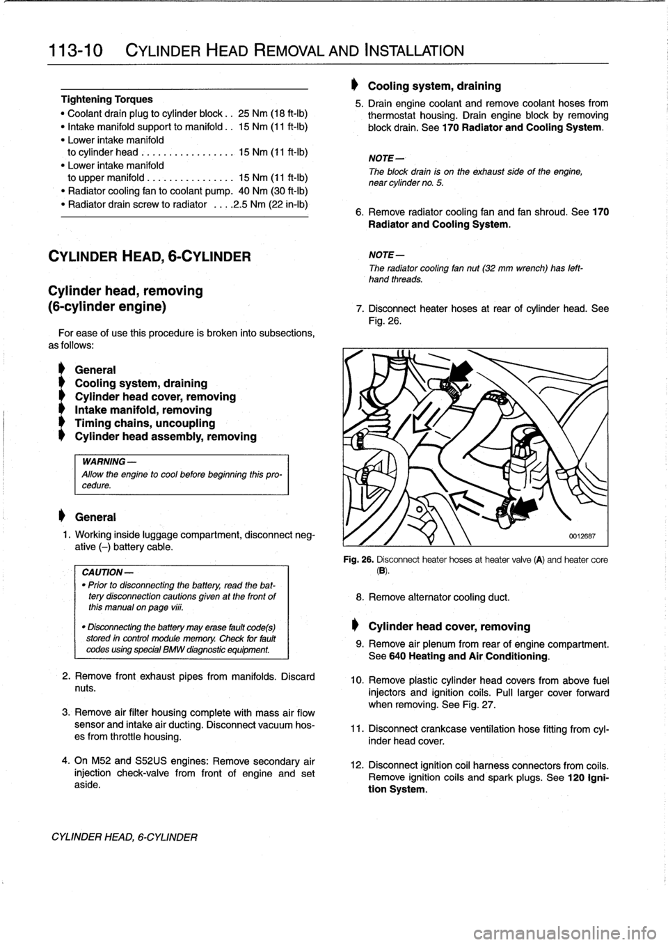
.
See
Fig
.
26
.
'i
8
.
Remove
alternator
cooling
duct
.
Cylinder
head
cover,
removing
0012687
Fig
.
26
.
Disconnect
heater
hoses
at
heater
valve
(A)
and
heater
core
(B)
.
9
.
Remove
air
plenum
from
rear
of
engine
compartment
.
See640
Heating
and
Air
Conditioning
.
10
.
Remove
plastic
cylinder
head
covers
from
above
fuel
injectors
and
ignition
coils
.
Pull
larger
cover
forward
when
removing
.
See
Fig
.
27
.
11
.
Disconnect
crankcase
ventílation
hose
fitting
from
cyl-
inder
head
cover
.
12
.
Disconnect
ignition
coil
harness
connectors
from
coiis
.
Remove
ignition
coiis
and
spark
plugs
.
See
120
Igni-
tion
System
.
Page 121 of 759
5
.
Remove
air
filter
housingcomplete
with
mass
air
flow
sensor
.
See113
Cylinder
HeadRemoval
and
Instal-
lation
.
6
.
Remove
oil
dipstick
guide
tube
mounting
bolt
.
Discon-
nect
oil
separator
hose
frombase
of
guide
tube
and
re-
move
tubefrom
oil
pan
(where
applicable)
.
See
Fig
.
10
.
NOTE-
The
guide
tube
is
sealed
in
the
blockusing
an
O-ring
.
Check
that
the
O-ring
comes
out
with
the
tube
.
Use
a
new
O-ring
when
installing
the
tube
.
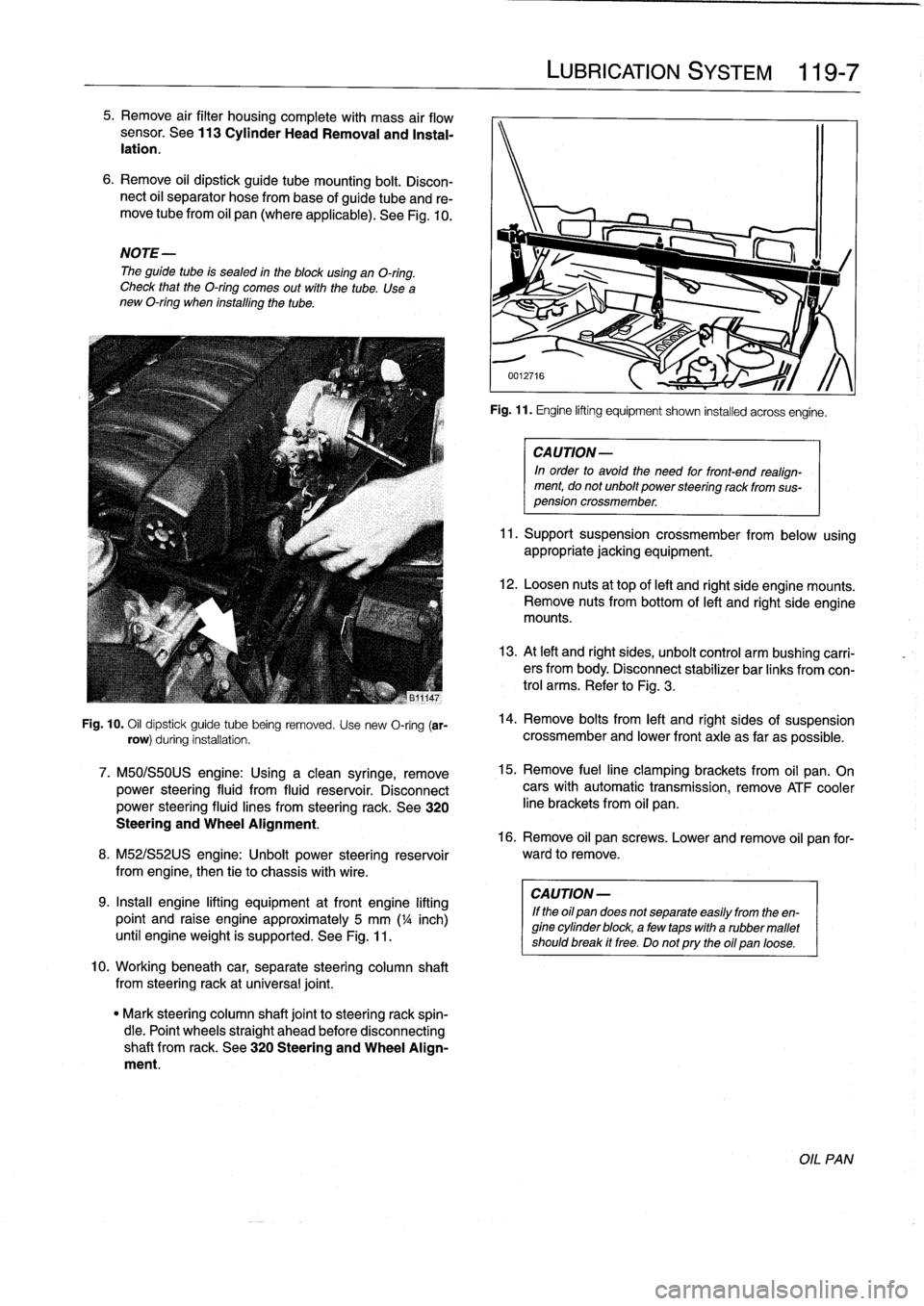
Fig
.
10
.
Oil
dipstick
guide
tube
being
removed
.
Use
new
O-ring
(ar-
row)
during
installation
.
7
.
M50/S50US
engine
:
Using
a
clean
syringe,
remove
power
steering
fluid
from
fluid
reservoir
.
Disconnect
power
steering
fluid
lines
from
steering
rack
.
See
320
Steering
and
Wheel
Alignment
.
8
.
M52/S52US
engine
:
Unbolt
power
steering
reservoir
from
engíne,
then
tie
to
chassis
with
wire
.
9
.
Insta¡¡
engine
lifting
equipment
atfront
engine
lifting
point
and
raise
engine
approximately
5
mm
('/a
inch)
until
engineweight
is
supported
.
See
Fig
.
11
.
10
.
Workingbeneath
car,
separate
steering
column
shaft
from
steeringrack
at
universal
joint
.
"
Mark
steering
column
shaft
jointto
steering
rack
spin-
dle
.
Point
wheels
straight
ahead
before
disconnecting
shaft
from
rack
.
See
320
Steering
and
Wheel
Align-
ment
.
LUBRICATION
SYSTEM
119
Fig
.
11
.
Engine
lifting
equipment
shown
installed
acrossengíne
.
CA
UTION-
In
order
to
avoid
the
need
for
front-end
realign-
ment,
donot
unbolt
power
steering
rack
from
sus-
pension
crossmember
.
11
.
Support
suspension
crossmember
from
below
using
appropriate
jacking
equipment
.
12
.
Loosen
nuts
at
top
of
left
and
right
side
engine
mounts
.
Remove
nuts
from
bottom
of
left
and
right
side
engine
mounts
.
13
.
At
left
and
right
sides,
unbolt
control
arm
bushíng
carri-
ers
from
body
.
Disconnect
stabilizer
bar
links
fromcon-
trol
arms
.
Refer
to
Fig
.
3
.
14
.
Remove
bolts
from
left
and
right
sides
of
suspension
crossmember
and
lower
front
axle
as
far
as
possible
.
15
.
Remove
fuelline
clamping
brackets
from
oil
pan
.
On
cars
with
automatic
transmission,
remove
ATF
cooler
line
brackets
from
oil
pan
.
16
.
Remove
oil
pan
screws
.
Lower
and
remove
oil
pan
for-
ward
to
remove
.
CA
UTION-
If
the
oil
pan
does
not
separate
easily
from
the
en-
gine
cylinder
block,
a
few
taps
with
a
rubber
mallet
shouldbreak
it
free
.
Do
notpry
the
oil
pan
loose
.
OIL
PAN
Page 130 of 759
120-
6
IGNITION
SYSTEM
Crankshaft
position/rpm
sensor,
testing
and
replacing
(front
mounted)
1
.
Disconnect
sensor
harness
connector
.
2
.
Using
a
digital
multimeter,
check
resistance
between
terminals
1
and
2
in
connector
.
See
Fig
.
10
.
n1
n2n3
Fig
.
10
.
Crankshaft
position/rpm
sensorconnector
.
Crankshaft
positionlrpm
sensor
specifications
"
Coil
resistance
(approx
.)
terminais
1
and
2
....
.
..
...
....
1280
±
10%
ohms
"
Air
gap
(sensor
distance
from
toothed
wheel)
..
.
.
........
.1
.0
±
0
.3
mm
(0
.04
±
0
.01
in
.)
3
.
If
the
resistance
is
not
correct,
the
sensor
is
faulty
and
should
be
replaced
.
NOTE
-
When
installing
the
new
sensor,
be
sure
thewiring
Is
rerouted
in
the
same
orientation
.
Secure
the
sensor
us-
ing
new
wire
ties
.
Tightening
Torque
"
Crankshaft
position/rpm
sensor
to
mounting
bracket
.........
.
.
5
t
1
Nm
(62
t
9
in-lb)
Crankshaft
position/rpm
sensor,
4
.
Installation
is
reverse
of
removal
.
Use
a
new
O-ring
replacing
(rear
mounted)
when
installing
sensor
.
Be
sure
wiring
is
rerouted
in
same
orientation
.
1
.
Disconnect
sensor
harness
connector
.
6502AGN56
2
.
Locatesensor
on
rear
left
sideof
cylinder
block
.
Re-
move
sensormounting
bolt
and
remove
sensorfrom
cylinder
block
.
IGNITION
SYSTEM
SERVICE
3
.
Installation
is
reverse
of
removal
.
Use
a
new
O-ring
when
installing
sensor
.
Be
sure
wiring
is
rerouted
in
same
orientation
.
Secure
sensor
using
new
wire
ties
.
NOTE-
It
may
be
easier
to
remove
the
sensor
working
from
the
underside
of
the
vehicle
.
Camshaft
Position
(CMP)
Sensor
The
camshaft
position
(CMP)
sensor
is
usedby
the
engine
management
system
for
sequential
fuel
injection
and
knock
control
.
Camshaft
position
(CMP)
sensor,
replacing
(4-cylinder
engine)
1
.
Remove
CMP
sensorfromtop
timing
cover,
just
above
coolantthermostat
housing
.
See
Fig
.
11
.
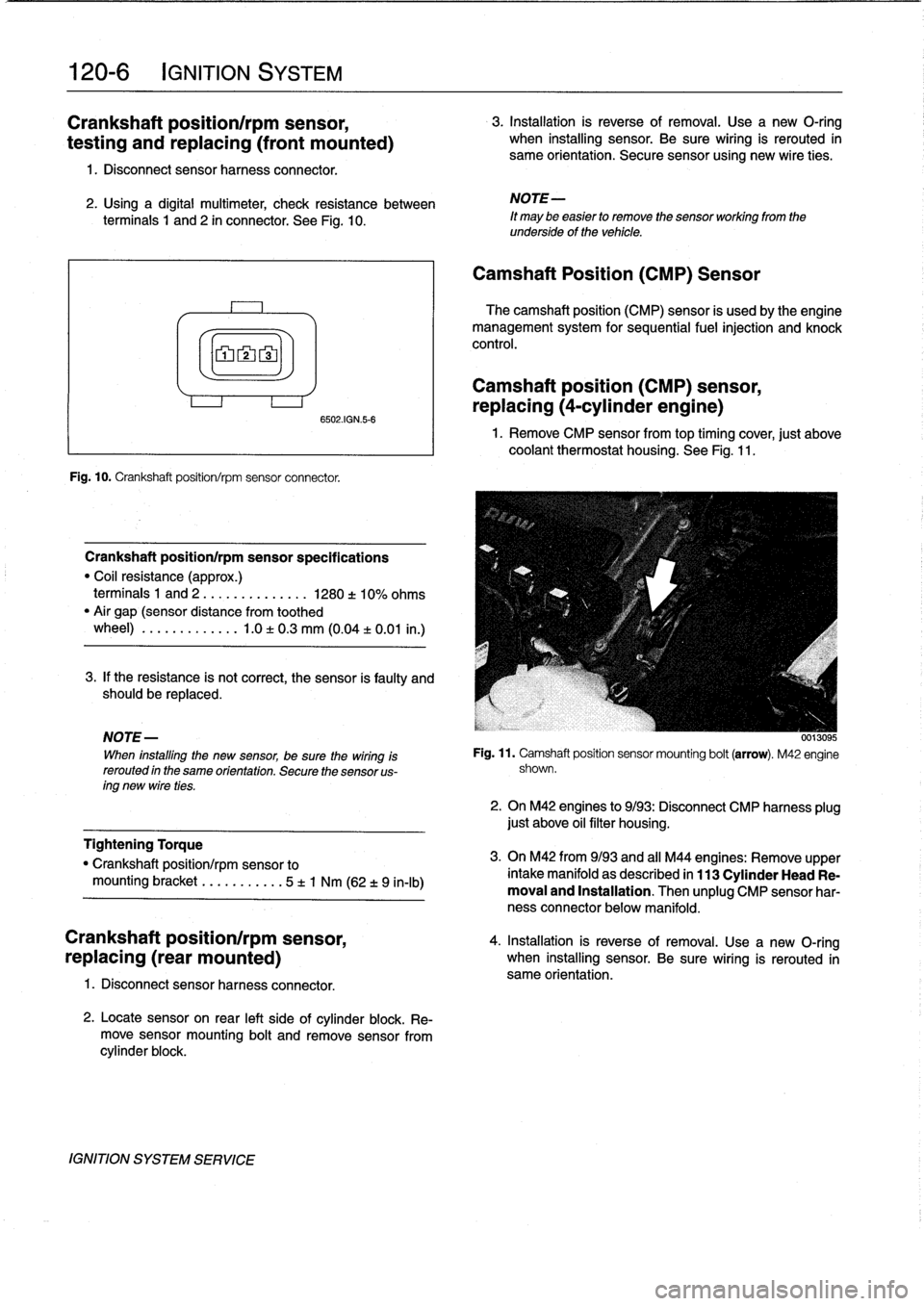
Fig
.
11
.
Camshaft
position
sensor
mounting
bolt
(arrow)
.
M42
engine
shown
.
2
.
On
M42
engines
to
9/93
:
Disconnect
CMP
harness
plug
just
above
oil
filter
housing
.
3
.
On
M42
from9/93
and
all
M44
engines
:
Remove
upper
intake
manifold
as
described
in
113
Cylinder
Head
Re-
moval
and
Installation
.
Then
unplug
CMP
sensor
har-
ness
connector
below
manifold
.
Page 131 of 759
Camshaft
position
(CMP)
sensor,
replacing
(6-cylinder
engine)
1
.
Remove
plastic
cover
from
above
fuel
injectors
.
2
.
Disconnect
harness
connector
from
VANOS
solenoid
and
unscrew
solenoid
from
VANOS
control
unit
.
Re-
"
Clean
contactsurface
on
engine
block
before
fnstall
move
oil
supply
line
from
VANOS
control
unit
.
See
117
ing
knock
sensors
.
Camshaft
Timing
Chain
.
3
.
Remove
camshaft
position
(CMP)
sensor
from
left
frontof
cylinder
head,
next
to
top
of
oil
filter
housing
.
"
Knock
sensor
to
cylinder
block
....
20
Nm
(15
ft
.
lbs
.)
4
.
Disconnect
CMP
sensor
harnessfrom
under
intake
manifold
.
5
.
Installation
is
reverse
of
removal
.
Use
a
new
O-ring
when
installing
sensor
.
Be
sure
wiring
is
rerouted
in
same
orientation
.
Tightening
Torques
"
CMP
sensor
to
cylinder
head
....
.
.
..
5
Nm
(3
.5
ft-Ib)
"
VANOS
oil
supply
pipe
to
VANOS
control
unit
...........
.
..
32
Nm
(24
ft-Ib)
"
VANOS
solenoid
to
VANOS
control
unit
...
.
.................
30
Nm
(22
ft-Ib)
Knock
sensors,
replacing
Knock
sensors
are
usedon
engines
with
Bosch
DME
M1
.7,
Bosch
DME
M3
.3
.1,
Bosch
DME
M5
.2,
and
Siemens
MS
41
.1
engine
management
systems
.
The
knocksensors
are
bolted
to
the
left
sideof
the
cylinder
block
and
monitor
the
combus-
tion
chamber
for
engine-damaging
knock
.
If
engine
knock
is
detected,
the
ignition
point
is
retarded
accordingly
via
the
en-
gine
control
module
.
CA
UTION-
"
Label
knock
sensorharness
connectors
before
disconnecting
them
.
The
connectors
must
not
be
interchanged
.
Engine
damage
may
result
if
the
sensors
are
monitoring
the
wrong
cytinders
.
"
Note
the
installed
angle
of
the
knock
sensoron
the
block
before
removing
it
.
Reinstall
the
sensor
in
the
same
position
.
Be
sure
to
usea
torque
wrench
when
tightening
the
sensormounting
bola
NOTE
-
"
On
M52
engines,
a
single
harness
connects
the
twosensors
to
the
main
harness
connector
.
The
shorter
cable
lead
fs
for
the
knock
sensor
for
cytinders
4,
5,
and
6
.
Tightening
Torque
IGNITION
SYSTEM
120-
7
0012730
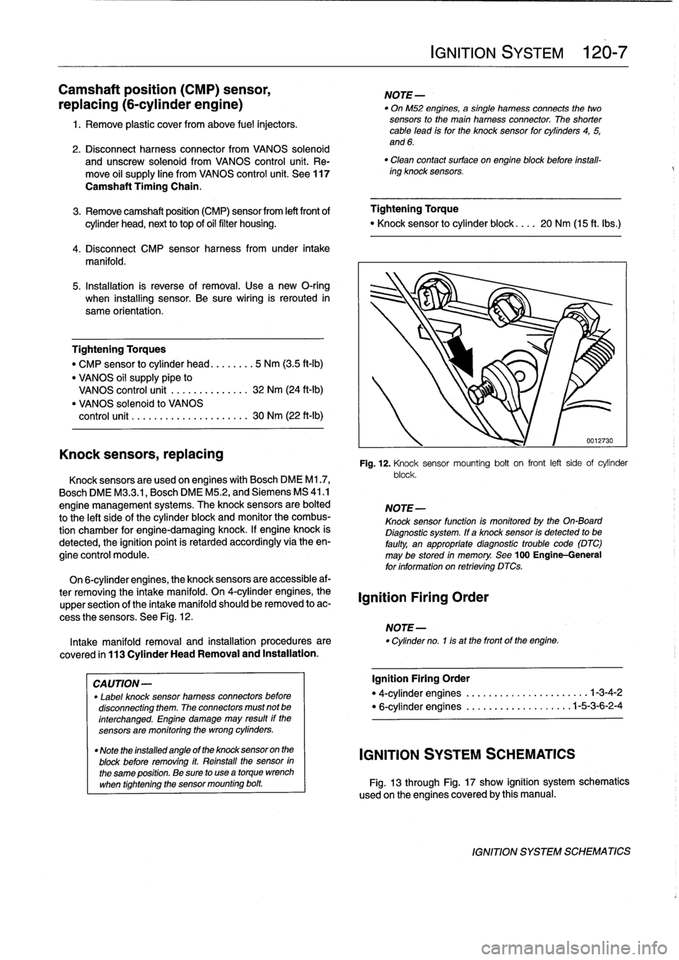
Fig
.
12
.
Knock
sensor
mounting
bolt
on
front
left
side
of
cylinder
block
.
NOTE-
Knock
sensor
function
Is
monitoredby
the
On-Board
Diagnostic
system
.
If
a
knock
sensor
is
detected
to
be
faulty,
an
appropriatediagnostic
trouble
code
(DTC)
may
be
stored
in
memory
.
See
100
Engine-General
for
information
on
retrieving
DTCs
.
On
6-cylinder
engines,
the
knock
sensors
are
accessible
af-
ter
removing
the
intake
manifold
.
On
4-cylinder
engines,
the
upper
section
of
the
intake
manifold
should
be
removed
to
ac-
cess
the
sensors
.
See
Fig
.
12
.
NOTE-
Intakemanifold
removal
and
installation
procedures
are
"
Cylinder
no
.
1is
at
the
front
of
the
engine
.
covered
in
113
Cylinder
HeadRemoval
and
Installation
.
Ignition
Firing
Order
Ignition
Firing
Order
"
4-cylinder
engines
.....
..
...
.
..........
.1-3-4-2
"
6-cylinder
engines
...........
..
.
.
..
..
1-5-3-6-2-4
IGNITION
SYSTEM
SCHEMATICS
Fig
.
13
through
Fig
.
17
show
ignition
system
schematics
usedon
the
enginescoveredby
this
manual
.
IGNITION
SYSTEM
SCHEMATICS
Page 144 of 759
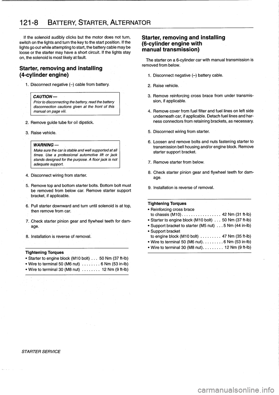
121-
8
BATTERY,
STARTER,
ALTERNATOR
1f
the
solenoid
audibly
cliicks
but
the
motor
does
not
turn,
Starter,
removing
and
installing
switch
on
the
lights
andtum
the
key
to
the
start
position
.
lf
the
(6-cylinder
engine
with
lights
go
out
while
attempting
to
start,
the
battery
cable
may
be
manual
transmission)
loose
or
the
starter
may
have
a
short
circuit
.
If
the
lights
stay
on,the
solenoid
is
most
likely
atfault
.
The
starter
on
a
6-cylinder
car
with
manual
transmission
is
Starter,
removing
and
installing
(4-cylinder
engine)
1
.
Disconnect
negative
(-)
battery
cable
.
1
.
Disconnect
negative
(-)
cable
from
battery
.
CAUTION-
Prior
to
disconnecting
the
battery,
read
the
battery
disconnection
cautions
given
at
the
front
of
this
manual
on
page
viii
.
2
.
Remove
guide
tube
for
oil
dipstick
.
3
.
Raise
vehicle
.
WARNING
-
Make
sure
the
car
ís
stable
and
wefl
supported
at
all
times
.
Use
a
professional
automotive
lift
or
jack
stands
designed
forthe
purpose
.
A
floor
jack
is
not
adequate
support
.
4
.
Disconnect
wiring
from
starter
.
5
.
Remove
top
and
bottom
starter
bolts
.
Bottom
bolt
must
be
removed
from
below
car
.
Remove
starter
support
bracket,
if
applicable
.
removed
from
below
.
2
.
Raise
vehicle
.
3
.
Remove
reinforcing
cross
bracefromunder
transmís-
sion,
if
applicable
.
4
.
Remove
cover
from
fuel
filter
and
fuel
lines
on
left
side
underneath
car,
if
applicable
.
Detach
fuel
lines
and
har-
ness
connectors
from
retainingbrackets,
as
necessary
5
.
Disconnect
wiring
from
starter
.
6
.
Loosen
andremove
bolts
and
nuts
fastening
starter
to
transmission
bell
housing
and/or
engine
block
.
Remove
starter
supportbracket
.
7
.
Remove
starter
from
below
.
8
.
Check
starter
pinion
gear
and
flywheel
teeth
for
dam-
age
.
9
.
Installation
is
reverse
of
removal
.
6
.
Pull
starter
downward
and
turn
until
solenoid
is
at
top,
Tightening
Torques
then
remove
from
car
.
"
Re¡
nforcing
cross
brace
to
chassis
(M10)
..
...............
42
Nm
(31
ft-Ib)
7
.
>Check
starter
pinion
gear
and
flywheel
teeth
for
dam-
"
Starter
to
engine
block
(M10
bolt)
...
50
Nm
(37
ft-Ib)
age
.
"
Support
bracket
to
starter
(M5
nut)
...
5
Nm
(44
in-lb)
"
Support
bracket
8
.
Installation
is
reverse
of
removal
.
to
engine
block
(M10
bolt)
.........
47
Nm
(35
ft-Ib)
"
Wire
to
terminal
50
(M6
nut)
.........
6
Nm
(53
ín-Ib)
"
Wire
to
terminal
30
(M8
nut)
.........
12
Nm
(9
ft-lb)
Tightening
Torques
"
Starter
to
engine
block
(M10
bolt)
...
50
Nm
(37
ft-lb)
Wire
to
terminal
50
(M6
nut)
........
6
Nm
(53
in-lb)
"
Wire
toterminal
30
(M8
nut)
...
,
..:.
12
Nm
(9
ft-Ib)
STARTER
SERVICE
Page 148 of 759
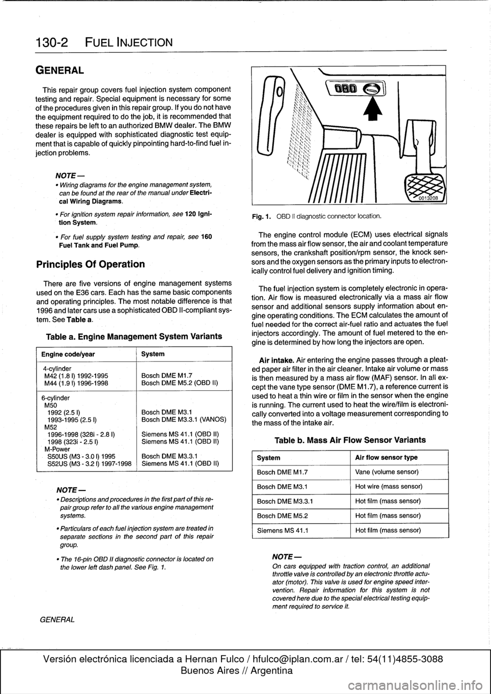
130-2
FUEL
INJECTION
GENERAL
This
repair
group
covers
fuel
injection
system
component
testing
and
repair
.
Special
equipment
is
necessary
for
some
of
the
procedures
given
in
this
repair
group
.
If
you
do
not
have
the
equipment
required
to
do
the
job,
it
is
recommended
that
these
repairs
be
left
to
an
authorized
BMW
dealer
.
The
BMW
dealer
is
equipped
with
sophisticated
diagnostic
test
equip-
ment
that
is
capable
of
quicklypinpointing
hard-to-find
fuel
in-
jection
problems
.
NOTE-
"
Wiring
diagrams
for
the
engine
management
system,
can
be
found
at
the
rear
of
the
manual
under
Electri-
cal
Wiring
Diagrams
.
"
For
ignition
system
repairinformation,
see120
Igni-
tion
System
.
"
For
fuel
supply
system
testing
and
repair,
see160
The
engine
control
module
(ECM)
uses
electrical
signals
Fuel
Tank
and
Fuel
Pump
.
from
the
mass
air
flow
sensor,
the
air
and
coolant
temperature
sensors,
the
crankshaft
position/rpm
sensor,
the
knock
sen
Principies
Of
Operation
sors
and
the
oxygen
sensorsas
the
primary
inputs
to
electron-
ically
control
fuel
delivery
and
ignition
timing
.
There
are
five
versions
of
engine
management
systems
usedon
the
E36
cars
.
Each
has
the
same
basic
components
and
operating
principles
.
The
most
notable
difference
is
that
1996
and
later
cars
use
a
sophisticated
OBD
II-compliant
sys-
tem
.
See
Table
a
.
Table
a
.
Engine
Management
System
Variants
Engine
code/year
1
System
4-cy1inder
M42
(1
.8
I)
1992-1995
Bosch
DME
Ml
.7
M44
(1
.91)
1996-1998
~
Bosch
DME
M5
.2
(OBD
II)
6-cylinder
M50
1992
(2.5
I)
Bosch
DME
M3
.1
1993-1995
(2.5
I)
Bosch
DME
M3
.3.1
(VANOS)
M52
1996-1998
(3281-
2
.8
I)
Siemens
MS
41
.1
(OBD
II)
1998
(3231
-
2
.5
I)
Siemens
MS
41
.1
(OBD
II)
M-Power
S50US
(M3
-
3
.01)
1995
Bosch
DME
M3
.3
.1
S52US
(M3
-
3
.21)
1997-1998
Siemens
MS
41
.1
(0131)
11)
NOTE-
-
Descriptions
and
procedures
in
the
first
partof
this
re-
pairgroup
refer
to
all
the
various
engine
management
systems
.
"
Particulars
of
each
fuel
injection
system
are
treated
in
separate
sections
in
the
second
part
of
this
repair
group
.
GENERAL
Fig
.1
.
OBD
II
diagnostic
connector
locatíon
.
The
fuel
injection
system
is
completely
electronic
in
opera-
tion
.
Air
flow
is
measured
electronically
via
a
mass
air
flow
sensor
and
additional
sensors
supply
information
about
en-
gine
operating
conditions
.
The
ECM
calculates
the
amount
of
fuel
needed
for
the
correct
air-fuel
ratio
and
actuates
the
fuel
injectors
accordingly
.
The
amount
offuel
metered
to
theen-
gine
is
determined
by
how
long
the
injectors
are
open
.
Airintake
.
Air
entering
the
engine
passes
through
a
pleat-
ed
paper
air
filter
in
the
air
cleaner
.
Intake
air
volume
or
mass
is
then
measured
bya
mass
air
flow
(MAF)
sensor
.
In
al¡
ex-
cept
the
vane
type
sensor
(DME
M1
.7),
a
reference
current
is
used
to
heat
a
thin
wireor
film
in
the
sensor
when
the
engine
is
running
.
The
current
used
to
heat
the
wire/film
is
electroni-
cally
converted
into
a
voltage
measurement
corresponding
to
the
mass
of
the
intake
air
.
Table
b
.
Mass
Air
Flow
Sensor
Variants
System
Al
r
flow
sensor
type
Bosch
DME
M1
.7
Vane
(volume
sensor)
Bosch
DME
M3
.1
Hot
wire
(mass
sensor)
Bosch
DME
M3
.3
.1
Hot
film
(mass
sensor)
Bosch
DME
M5
.2
Hot
film
(mass
sensor)
Siemens
MS
41
.1
Hot
film
(mass
sensor)
"
The
16-pin
OBD
11
diagnostic
connector
is
located
on
NOTE-
the
lower
left
dashpanel
.
See
Fig
.
1
.
On
cars
equipped
wíth
tractioncontrol,
an
additional
throttle
valve
is
controlled
by
an
electronic
throttle
actu-
ator
(motor)
.
This
valve
is
used
for
engine
speed
inter
vention
.
Repair
information
forthis
system
is
notcovered
here
due
to
the
special
electrical
testing
equip-
ment
required
to
service
it
.
Page 155 of 759
Oxygen
Sensor
FUEL
DELIVERY
TESTS
FUEL
INJECTION
130-
9
"
Voltage
at
¡dle
..
.
..
..
....
0
.2
to
0
.8
VDC,
fluctuating
Checking
fuel
delivery
is
afundamental
part
of
trouble-
shooting
and
diagnosing
the
engine
management
system
.
Fuel
pressure
directly
influences
fuel
delivery
.
An
accurate
NOTE-
fuel
pressure
gauge
will
be
needed
to
make
the
tests
.
To
check
sensorresponse
to
lean
and
rich
mixtures,
createenairleak,
orpull
vacuumhoseofffue¡
pressure
There
are
three
significant
fuel
delivery
values
to
be
mea-
regulator
to
increase
fuel
pressure
.
sured
:
3
.
Separate
sensorharness
connector
from
sensor
.
Check
for
battery
voltage
between
terminals
3
and
4
(green
wire
and
brown
wire)
in
main
wiring
harness
side
of
con-
nector
with
engine
running
.
If
voltage
is
not
present,
check
oxygen
sensor
heater
relay
.
See610
Electrical
Component
Locations
.
4
.
Check
heater
element
resistance
between
terminals
3
and
4
in
sensor
side
of
connector
.
If
element
is
electri-
cally
open
(no
continuity),
replace
sensor
.
NOTE-
The
oxygen
sensor
heater
relay
is
mounted
in
the
main
power
distributfon
box
in
the
left
rear
of
the
engine
com-
partment
.
Refer
to
Fig
.
6
.
The
heater
relay
is
energized
wíth
positive
(+)
battery
voltage
from
the
main
relayanda
switched
ground
from
the
ECM
.
See
Electrical
Wir-
ing
Diagrams
.
"
Oxygen
sensor
to
exhaust
pipe
...
..
55
Nm
(41
ft-Ib)
"
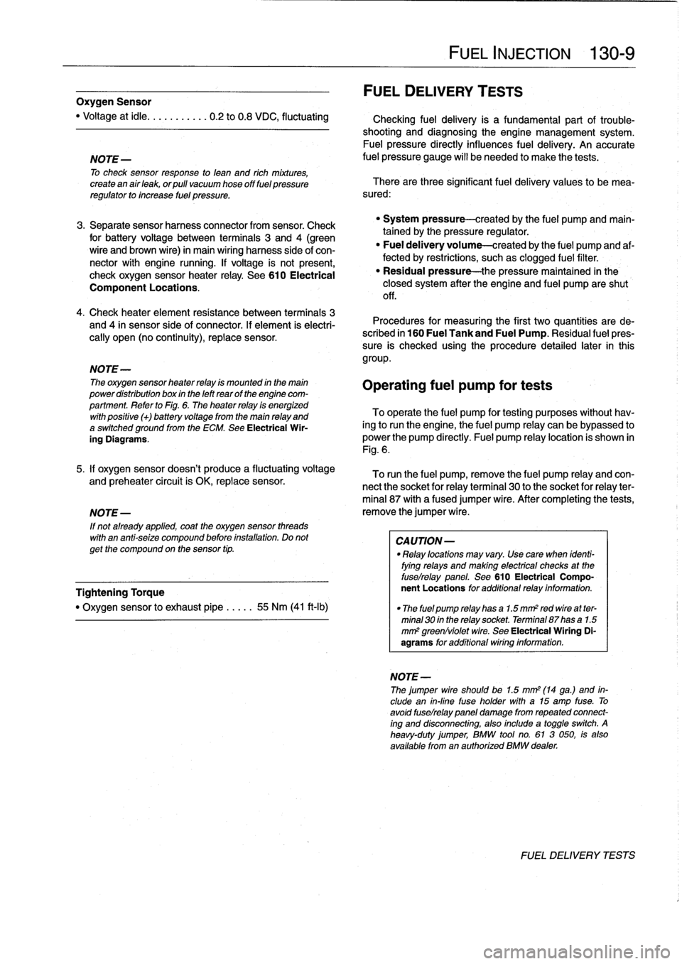
System
pressure-created
by
the
fuel
pump
and
main-
tained
by
the
pressure
regulator
.
"
Fuel
delivery
volume-created
by
the
fuel
pump
and
af-
fected
by
restrictions,
suchasclogged
fuel
filter
.
"
Residual
pressure-the
pressure
maintained
in
the
closed
system
after
the
engine
and
fuel
pump
are
shut
off
.
Procedures
for
measuring
the
first
two
quantities
arede-
scribed
in
160
Fuel
Tank
and
Fuel
Pump
.
Residual
fuel
pres-
sure
is
checked
using
the
procedure
detailed
later
in
this
group
.
Operating
fuel
pump
fortests
To
operate
the
fuel
pump
for
testing
purposes
without
hav-
íng
to
runthe
engine,
the
fuel
pump
relay
can
be
bypassed
to
power
the
pump
directly
.
Fuel
pump
relay
location
is
shown
in
Fig
.
6
.
5
.
¡f
oxygen
sensor
doesn't
produce
a
fluctuating
voltage
To
runthe
fuel
pump,
remove
the
fuel
pump
relay
and
con-
and
preheater
circuit
is
OK,
replace
sensor
.
nect
the
socket
for
relayterminal
30
to
the
socket
for
relay
ter-
mina¡
87
with
a
fused
jumper
wire
.
After
completing
the
tests,
NOTE-
remove
the
jumper
wire
.
If
not
already
applied,
coat
the
oxygen
sensor
threads
with
an
anti-seize
compound
before
installation
.
Do
not
CAUTION-
getthe
compound
on
the
sensor
tip
.
"
Relay
locations
may
vary
.
Use
care
when
identi-
fying
relays
and
making
electrical
checks
at
the
fuselrelay
panel
.
See
610
Electrical
Compo
Tightening
Torque
nent
Locations
for
additional
relay
information
.
"
The
fuel
pump
relay
has
a
1
.5
mm2
red
wire
at
ter-
minal
30
in
the
relay
socket
.
Terminal
87
has
a
1
.5
mm
2
greenlviolet
wire
.
See
Electrical
Wiring
Di-
agrams
for
additional
wiring
information
.
NOTE-
Thejumper
wire
should
be
1.5
mm2
(14
ga
.)
and
in-
clude
an
in-line
tuse
holder
with
a15
amp
tuse
.
To
avoid
fuselrelay
panel
damage
from
repeated
connect-
ing
and
disconnecting,
also
include
a
toggle
switch
.
A
heavy-duty
jumper,
BMW
tool
no
.
61
3
050,
is
also
available
from
an
authorized
BMW
dealer
.
FUEL
DELIVERYTESTS
Page 161 of 759
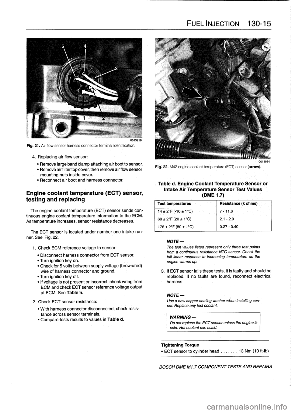
u0
I
.[
Ia
Fig
.
21
.
Air
flow
sensor
harness
connector
terminal
identification
.
4
.
Replacing
air
flow
sensor
:
"
Remove
large
band
clamp
attaching
air
boot
to
sensor
.
"
Remove
airfiltertop
cover,
then
remove
airflow
sensor
mounting
nuts
inside
cover
.
"
Reconnect
air
boot
and
harness
connector
.
Engine
coolant
temperature
(ECT)
sensor,
testing
and
replacing
The
engine
coolant
temperature
(ECT)
sensor
sends
con-
tinuous
engine
coolant
temperature
information
to
the
ECM
.
As
temperature
increases,
sensor
resistance
decreases
.
"
With
harness
connector
disconnected,
check
resis-
tance
across
sensor
terminals
.
"
Compare
tests
results
to
values
in
Table
d
.
FUEL
INJECTION
130-
1
5
0011984
Fig
.
22
.
M42
engine
coolant
temperature
(ECG
sensor
(arrow)
.
Table
d
.
Engine
Coolant
Temperature
Sensoror
Intake
Air
TemperatureSensor
Test
Values
(DME
1
.7)
Test
temperatures
Resistance
(k
ohms)
',
14±2°F(-10t1°C)
7-11
.6
68±2°F
(20
t
1
°C)
2
.1
-2
.9
176
±
2°F
(80
t
V
C)
0
.27-0
.40
The
ECT
sensor
is
located
under
number
one
intake
run-
'
ner
.
See
Fig
.
22
.
NOTE-
1
.
Check
ECM
referente
voltage
to
sensor
:
The
test
values
listed
represent
only
three
test
points
from
a
continuous
resistance
NTC
sensor
.
Check
the
"
Disconnect
harness
connectorfrom
ECT
sensor
.
full
linear
response
to
increasing
temperature
as
the
"
Turn
ignition
key
on
.
engine
warms
up
.
"
Check
for
5
volts
between
supply
voltage
(brown/red)
wire
of
harness
connector
and
ground
.
3
.
If
ECT
sensor
fails
these
tests,
it
is
faulty
and
should
be
"
Turn
ignition
key
off
.
replaced
.
If
no
faults
are
found,
reconnect
electrical
"
If
voltage
is
not
present
or
incorrect,
check
wring
from
harness
.
ECM
and
check
ECT
sensor
reference
voltage
output
at
ECM
.
See
Table
h
.
NOTE-
2
.
Check
ECT
sensor
resistance
:
Use
a
new
copper
sealing
washer
when
installing
sen-
sor
.
Reptace
any
lost
coolant
.
WARNING
-
Do
not
replace
the
ECT
sensor
unlessthe
engine
is
cold
.
Hot
coolant
can
scald
.
Tightening
Torque
"
ECT
sensor
to
cylinder
head
.....
..
13
Nm
(10
ft-Ib)
BOSCH
DME
M1
.7
COMPONENT
TESTS
AND
REPAIRS
Page 168 of 759
130-
2
2
FUEL
INJECTION
Mass
air
flow
sensor,
replacing
1
.
Disconnect
harness
connector
and
intake
air
bootfrom
air
flow
sensor
.
See
Fig
.
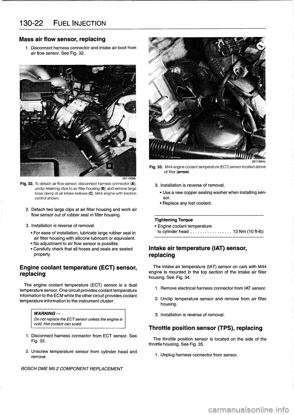
32
.
Fig
.
32
.
To
detach
air
flow
sensor,
disconnect
harness
connector
(A)
;
3
.
Installation
is
reverse
of
removal
.
unclip
retainíng
clips
to
aír
filter
housing
(B)
;
andremove
large
hose
clamp
at
air
intake
bellows
(C)
.
M44
engine
with
traction
"
Use
a
new
copper
sealing
washer
when
installing
sen-
control
shown
.
sor
.
"
Replace
any
lost
coolant
.
2
.
Detachtwo
large
clipsat
air
filter
housing
and
work
air
flow
sensor
out
of
rubber
seal
in
filter
housing
.
Tightening
Torque
3
.
Installation
is
reverse
of
removal
.
"
Engine
coolant
temperature
"
For
ease
of
installation,
lubricate
large
rubber
seal
in
to
cylinder
head
.............
.
..
.
13
Nm
(10
ft-Ib)
air
filter
housing
with
silicone
lubricant
or
equivalent
.
"
No
adjustment
to
air
flow
sensor
is
possible
.
"
Carefully
check
that
all
hoses
and
seals
are
seated
Intake
air
temperature
(IAT)
sensor,
properly
.
replacing
Engine
coolant
temperature
(ECT)
sensor,
replacing
The
engine
coolant
temperature
(ECT)sensor
is
a
dual
temperature
sensor
.
One
circuít
provides
coolant
temperature
information
to
the
ECM
while
the
other
circuít
provides
coolant
temperature
information
to
the
instrument
cluster
.
WARNING
-
Do
not
replace
the
ECT
sensor
unless
the
engine
is
cold
.
Hot
coolant
can
scald
.
1
.
Disconnect
harness
connector
from
ECT
sensor
.
See
Fig
.
33
.
2
.
Unscrew
temperature
sensorfrom
cylinder
head
and
remove
BOSCH
DME
M5
.2
COMPONENT
REPLACEMENT
U1111
bis4a
Fig
.
33
.
M44
engine
coolant
temperature
(ECT)
sensor
located
above
oil
filter
(arrow)
.
The
intake
air
temperature
(IAT)
sensoron
cars
with
M44
engine
is
mounted
in
thetop
section
of
the
intake
air
filter
housing
.
See
Fig
.
34
.
1
.
Remove
electrical
harness
connector
from
IAT
sensor
.
2
.
Unclip
temperature
sensor
and
remove
from
air
filter
housing
.
3
.
Installation
is
reverse
of
removal
.
Throttle
position
sensor
(TPS),
replacing
The
throttle
position
sensor
is
located
on
the
side
of
the
throttle
housing
.
See
Fig
.
35
.
1
.
Unplug
harness
connector
from
sensor
.
Page 169 of 759
001ía4
i
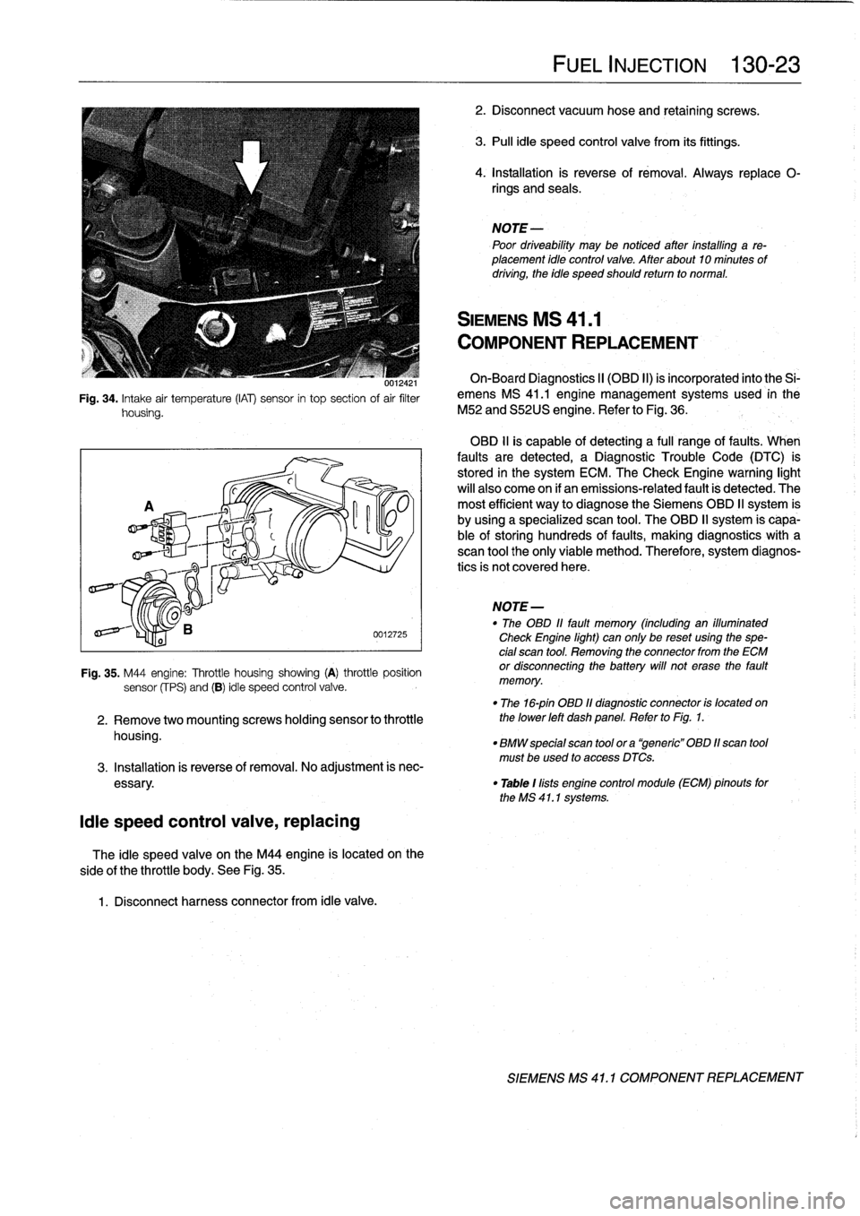
Fig
.
34
.
Intake
air
temperature
(IAT)
sensor
in
top
section
of
air
filter
housing
.
¡die
speed
control
valve,
replacing
side
of
the
throttle
body
.
See
Fig
.
35
.
1
.
Disconnect
harness
connector
from
¡die
valve
.
0012725
Fig
.
35
.
M44
engine
:
Throttle
housing
showing
(A)
throttle
position
sensor
(fPS)
and
(B)
¡die
speed
control
valve
.
2
.
Remove
twomountingscrews
holding
sensor
to
throttle
housing
.
The
¡die
speed
valve
on
the
M44
engine
is
located
on
the
FUEL
INJECTION
130-23
2
.
Disconnect
vacuum
hose
and
retaining
screws
.
3
.
Pull
¡die
speed
control
valve
from
its
fittings
.
4
.
Installation
is
reverse
of
rémoval
.
Always
replace
0-
rings
and
seals
.
NOTE
Poor
driveability
may
be
notíced
after
installing
a
re-
placement
¡dio
control
valve
.
After
about10
minutes
of
driving,
the
idie
speed
should
retum
to
normal
.
SIEMENS
MS
41
.1
COMPONENT
REPLACEMENT
On-Board
Diagnostics
II
(OBD
II)
is
incorporated
into
the
Si-
emens
MS
41
.1
engine
management
systems
used
in
the
M52
and
S52US
engine
.
Refer
to
Fig
.
36
.
OBD
11
is
capable
of
detecting
a
fui¡
range
offaults
.
When
faults
are
detected,
a
Diagnostic
Trouble
Code
(DTC)
is
stored
in
the
system
ECM
.
The
Check
Engine
warning
light
will
also
come
on
if
an
emissions-related
fault
is
detected
.
The
most
efficient
way
to
diagnose
the
Siemens
OBD
II
system
is
by
using
a
specialized
scan
tool
.
The
OBD
II
system
is
capa-
ble
of
storing
hundreds
of
faults,
making
diagnostics
with
a
scan
tool
the
only
viable
method
.
Therefore,
system
diagnos-
tics
is
not
covered
here
.
NOTE
-
"
The
OBD
11
fault
memory
(including
an
illuminated
Check
Engine
light)
can
only
be
reset
using
the
spe-
cial
scan
tool
.
Removing
the
connector
from
the
ECM
or
disconnecting
the
battery
will
not
erase
the
fault
memory
.
"
The
16-pin
OBD
11
diagnostic
connector
is
located
on
the
lower
left
dash
panel
.
Refer
to
Fig
.
1
.
"
BMW
special
scan
tool
ora
"generic"
OBD
11scan
tool
must
be
used
to
access
DTCs
.
3
.
Installation
is
reverse
of
removal
.
No
adjustment
is
nec
essary
.
"
Table
1
lists
engine
control
module
(ECM)
pinouts
forthe
MS
41
.1
systems
.
SIEMENS
MS
41
.
1
COMPONENT
REPLACEMENT