heating BMW 328i 1995 E36 User Guide
[x] Cancel search | Manufacturer: BMW, Model Year: 1995, Model line: 328i, Model: BMW 328i 1995 E36Pages: 759
Page 145 of 759
Starter,
removing
and
installing
(6-cylinder
engine
with
automatic
transmission)
The
starter
on
a
6-cylinder
car
with
automatic
transmission
ís
removed
from
above
.
It
is
necessary
to
remove
the
íntake
manifold
and
disconnect
a
number
of
electrical
harness
con-
nectors
.
1
.
Disconnect
negative
(-)
battery
cable
.
2
.
Remove
air
plenum
from
rear
of
engine
compartment
.
See640
Heating
and
Air
Conditioning
.
3
.
Remove
top
enginecovers
.
See
Fig
.
9
.
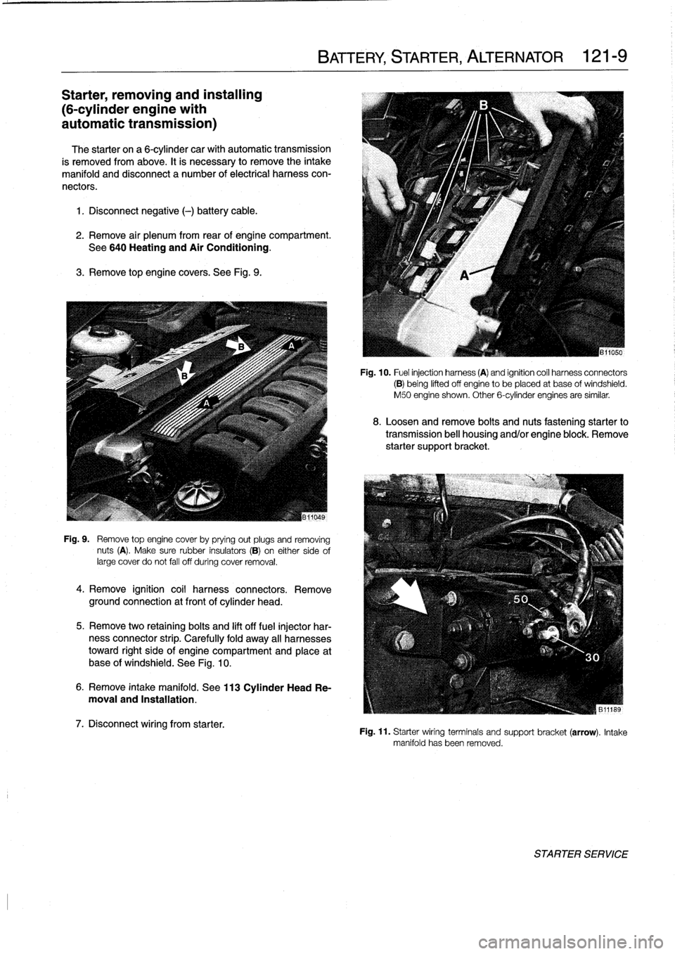
Fig
.
9
.
Remove
top
engine
cover
by
prying
out
plugs
and
removing
nuts
(A)
.
Make
sure
rubber
insulators
(B)
on
either
sideof
large
cover
do
not
fall
off
during
cover
removal
.
4
.
Remove
ignition
coil
harness
connectors
.
Remove
ground
connection
at
front
of
cylinder
head
.
5
.
Remove
two
retaining
bolts
and
lift
off
fuel
injector
har-
ness
connector
strip
.
Carefully
fold
away
all
harnesses
toward
right
side
of
engine
compartment
and
place
at
base
of
windshield
.
See
Fig
.
10
.
6
.
Remove
intake
manifold
.
See
113
Cylinder
Head
Re-
moval
and
Installation
.
7
.
Disconnect
wiring
from
starter
.
BATTERY,
STARTER,
ALTERNATOR
121-
9
Fig
.
10
.
Fuel
injection
harness
(A)
and
ignition
coíl
harness
connectors
(B)
being
lifted
off
engine
to
be
placed
at
base
ofwindshield
.
M50
engine
shown
.
Other
6-cylinder
engines
are
similar
.
8
.
Loosen
and
remove
bolts
and
nuts
fastening
starter
to
transmission
bell
housing
and/or
engine
block
.
Remove
starter
support
bracket
.
Fig
.
11
.
Starter
wiring
terminals
and
support
bracket(arrow)
.
Intake
manifold
has
been
removed
.
STARTER
SERVICE
Page 170 of 759
130-24
FUEL
INJECTION
Jo
'0
o_A
í1
RELAY
..
.
.
CAMSHAFT
POSITION
SENSOR
'
.
~'
~
:UhI~IIUH~W~`bY~7~d~t~II7
.
.
.
,
1111111
~ilf
ASC
TERMINAL
15
MEMORY
POWER
CRANKSHAFT
POSITION
qtcMSENSOR
THROTTLE
POSITION
ENGINE
COOLANT
TEMP
FUELTANK
PRESSURE
SENSOR
S-EML
S-MSR
S-ASC
VEHICLE
SPEED
LOW
FUEL
LEVEL
A/C
SWITCH
ON
(AC)
E36
IHKA
COMPRESSOR
"ON"
SIGNAL
(KO)
INDIVIDUAL
SERIAL
NUMBER
SIEMENS
MS
41
.
1
COMPONENT
REPLACEMENT
FUEL
PUMP
RELAY
CONTROL
AUX
GROUND
P
MAIN
GROUND
AC
COMPRESSOR
RELAY
CONTROL
~®
SECONDARY
AIR
INJECTION
AIR
PUMP
RELAY
CONTROL
-
M
PRE
CAT
POST
CAT
m
nXYGEN
SENSOR
ys
U
~
4
,
HEATING
FUELINJECTOR
CONTROL
(
MS
41
.1
(
MS
PURGE
CONTROL
VALVE
//
PURGE
'
CANISTERSHUT-OFF
VALVE
ECM
RELAY
CONTROL
IGNITION
COILS
CONTROL
1
ASC
o
ayi
THROTTLE
POTENTIOMETER
POWER
,
al
;
..
i
r71a
.
"a
fn7111,
/
r
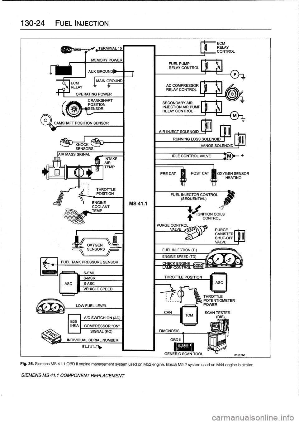
Fig
.
36
.
Siemens
MS
41
.1
OBD
II
engine
management
system
usedon
M52
engine
.
Bosch
M5
.2
systemusedon
M44
engine
is
similar
.
Page 191 of 759
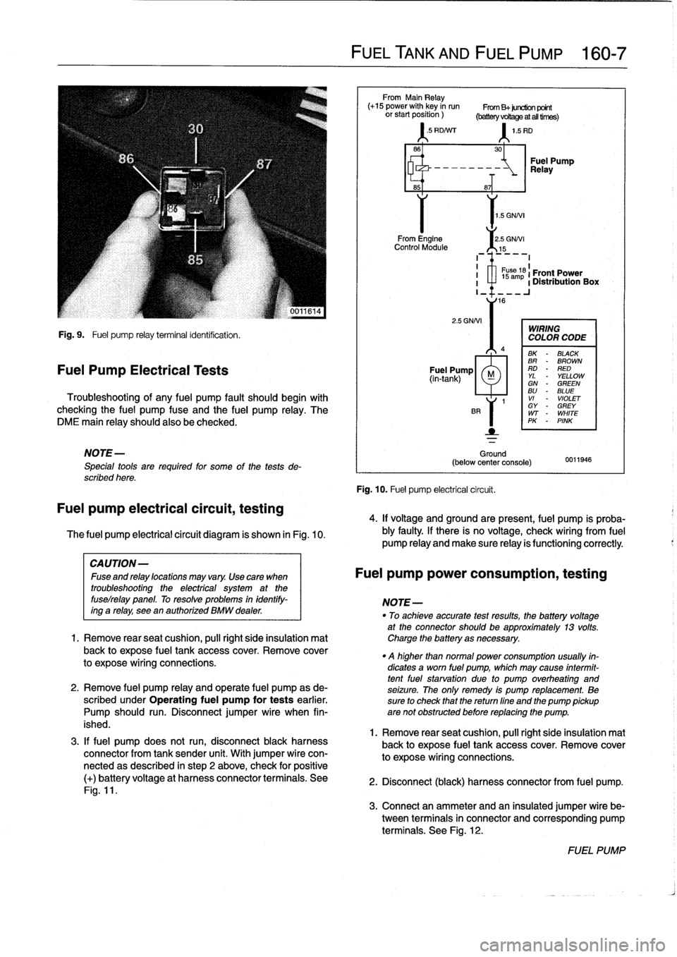
Fig
.
9
.
Fuel
pump
relay
terminal
identification
.
Fuel
Pump
Electrical
Tests
Troubleshooting
of
any
fuel
pump
fault
should
begin
with
checking
the
fuel
pump
fuse
and
the
fuel
pump
relay
.
The
DME
main
relay
should
also
be
checked
.
NOTE-
Special
tools
are
requíred
for
some
of
the
tests
de-
scribed
here
.
Fuel
pump
electrical
circuit,
testing
The
fuel
pump
electrical
circuit
diagram
is
shown
in
Fig
.
10
.
3
.
If
fuel
pump
does
not
run,
disconnect
black
harness
connector
from
tank
sender
unit
.
With
jumper
wire
con-
nectedas
described
in
step
2
above,
check
for
positive
(+)
batteryvoltage
at
harness
connector
terminals
.
See
Fig
.
11
.
FUEL
TANK
AND
FUEL
PUMP
160-
7
From
Main
Relay
(+15
power
with
key
in
run
From
B+juretion
point
orstartposition)
(batteryvoRageatalltirnes)
'
.5
RD/Nrr
1
.5
RD
1
.5
GNNI
From
Engine
2
.5
GNNI
Control
Module
15
2
.5
GNNI
Ground
(below
center
console)
Fig
.
10
.
Fuel
pump
electrical
circuit
.
30
-~
Relay
Fuel
Pump
8~T
I
1
s
ám
61
Front
Power
I
a
1
Distribution
Box
I_
16
WIRING
COLOR
CODE
BK
-
BLACK
BR
-
BROWN
Fuel
Pump
RD
-
RED
(in-tank)
M
YL
YELLOWGN
-
GREENBU
-
BLUE
1
VI
-
VIOLET
GY
-
GREY
WT
-
WHITE
PK
-
PINK
0011946
4
.
If
voltage
and
groundare
present,
fuel
pump
is
proba-
bly
faulty
.
If
there
is
no
voltage,
check
wiring
From
fuel
pump
Reay
and
make
sure
Reay
is
functioning
correctly
.
CAUTION-
Fuseandrelaylocationsmayvary
.
Usecara
when
Fuel
pump
power
consumption,
testing
troubleshooting
the
electrical
system
at
the
fuselrelay
panel
.
To
resolve
problems
in
identify-
NOTE-
ing
a
relay,
see
en
authorízed
BMW
dealer
.
"
To
achieveaccurate
testresults,
fhe
battery
voltage
at
the
connector
should
be
approximately
13
volts
.
1.
Remove
rearseat
cushion,
pull
right
side
insulation
mat
Charge
the
battery
asnecessary
.
back
to
expose
fuel
tank
accesscover
.
Remove
cover
.
q
higher
than
normal
power
consumption
usually
fin-
to
expose
wiring
connections
.
dicates
a
worn
fuel
pump,
which
may
cause
intermit-
tentfuel
starvation
due
lo
pump
overheating
and
2
.
Remove
fuel
pump
relay
and
opérate
fuel
pump
as
de-
seizure
.
The
only
remedy
is
pump
replacement
.
Be
scribed
under
Operating
fuel
pump
for
tests
earlier
.
sure
to
check
that
thereturn
fine
and
the
pump
pickup
Pump
should
run
.
Disconnect
jumper
wire
when
fin-
are
not
obstructed
before
replacing
the
pump
.
ished
.
1
.
Remove
rear
seat
cushion,
pull
right
side
insulation
mal
back
to
expose
fuel
tank
accesscover
.
Remove
cover
to
expose
wiring
connections
.
2
.
Disconnect
(black)
harness
connector
from
fuel
pump
.
3
.
Connect
an
ammeter
and
an
insulated
jumper
wire
be-
tween
terminals
in
connector
and
corresponding
pump
terminals
.
See
Fig
.
12
.
FUEL
PUMP
Page 195 of 759
170
Radiator
and
Cooling
System
GENERAL
.
.
.....
.
...
.
.
.
.
.
....
.
.
.
.
.
.
.
.170-1
Coolant
Pump
and
Thermostat
........
.
.
.
.
170-1
Radiator
and
Expansion
Tank
.........
.
...
170-1
Cooling
Fans
.
....
.
.
.
.
.
.
.
.
.
.....
.
......
170-2
Warnings
and
Cautions
.
.
.
.
.
.
.
.
.
.
.
.
...
.
.
.
170-2
TROUBLESHOOTING
...
.
.
.
...
.
.
.
.
.
.
.
.
.170-2
Cooling
System
Pressure
Test
...
.
.
.
.
.
.
.
.
.
170-3
Thermostat
Quick
Check
.
.
.
.
...
.
.
.
.
.
.
.
.
.
170-3
Temperature
Gauge
Quick
Check
.
.
.
.
.
.
.
.
.
170-3
Cooling
fan,
testing
.
.
.
.
........
.
.
.
.
.
.
.
.
.
170-4
COOLING
SYSTEM
SERVICE
.
.
.
.
.
.
.
.
.
.
170-5
Coolant,draining
and
filling
.
.
......
.
.
.
.
.
..
170-5
Cooling
system,
bleeding
(radiator
with
integral
expansion
tank)
.....
170-6
GENERAL
This
section
covers
repair
and
troubleshooting
information
for
the
engine
cooling
system
.
For
heater
core
and
related
heating
and
air
conditioning
components,
see640
Heating
and
Air
Conditioning
.
Coolant
Pump
and
Thermostat
A
centrifuga¡-type
coolant
pump
is
mounted
to
the
front
of
the
engíne
.
The
belt-driven
pump
circulates
coolant
through
the
system
whenever
the
engíne
is
running
.
A
thermostat
con-
trols
the
flow
of
coolant
into
the
radiator
.
When
the
engíne
is
cold
the
thermostat
is
closed
so
coolant
bypasses
the
radiator,
recirculating
from
the
engíne
directly
back
to
the
pump
.
When
the
engíne
reaches
operating
tem-
perature,
the
thermostat
opens
and
coolant
circulates
through
the
whole
system
including
the
radiator
.
Radiator
and
Expansion
Tank
The
radiator
is
a
crossflow
design
.
A
translucent
expansion
tank
provides
for
coolant
expansion
at
higher
temperatures
and
easy
monitoringof
the
coolant
leve¡
.
On
4-cylinder
modeis,
the
radiator
expansion
tank
is
integral
with
the
radiator
.
See
Fig
.
1
.
RADIATOR
AND
COOLING
SYSTEM
170-1
Belt-driven
cooling
fan,
replacing
.
.......
.
.
.
170-7
Electric
cooling
fan,
replacing
.
.
.
.....
.
.
.
.
.
170-8
Auxiliary
cooling
fan,
replacing
.
.
.....
.
.
.
.
.
170-8
Thermostat,
replacing
.
.
.
.
.
.
.
.
.
.....
.
.
.
.
.
170-9
Coolant
pump,
replacing
..........
.
.
.
.
.
.
170-10
RADIATOR
SERVICE
.....
.
......
.
.
.
.
.
.
170-11
Radiator,
removing
and
installing
....
.
.
.
.
.
.
170-11
TABLES
a
.
Coolant
Temperature
Sensor
Wire
Colors
...
.
..
.
.
170-3b
.
Auxiliary
Cooling
Fan
Switching
Temperatures
.:.
.170-4
c
.
Auxiliary
Cooling
Fan
Temperature
Switch
Tests
..
..
.
...
...
.
.............
.
..
.
.
170-5d
.
Cooling
System
Capacities
..............
..
.
.
.
170-6
A
.
Expansion
tank
C
.
Dualtemperature
fan
switch
B
.
Radiator
drain
screw
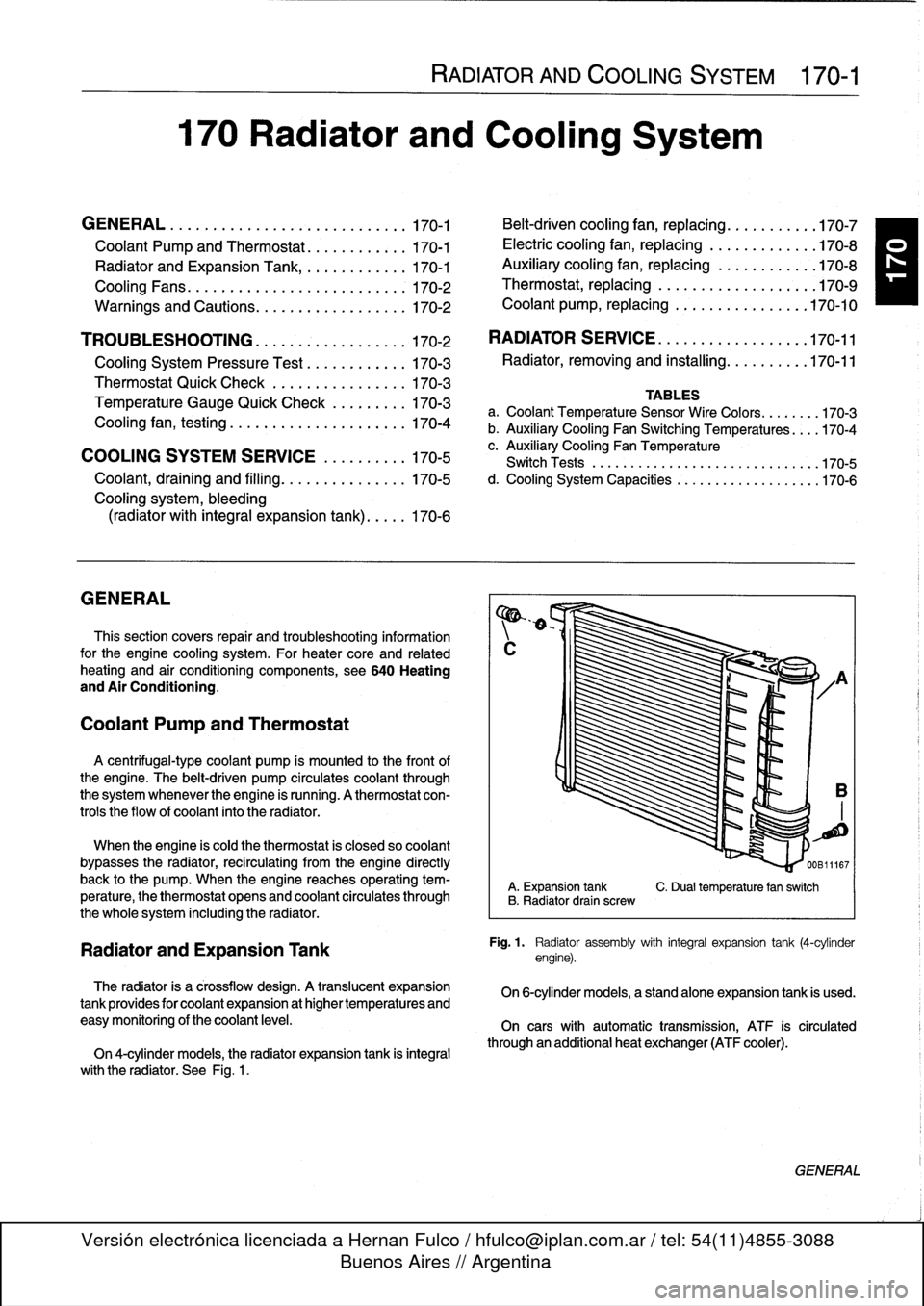
Fig
.
1
.
Radiator
assembly
with
integral
expansion
tank
(4-cylinder
engine)
.
On
6-cylinder
models,
a
standalone
expansion
tank
is
used
.
On
cars
with
automatic
transmission,
ATF
is
circulated
through
an
additional
heat
exchanger
(ATF
cooler)
.
GENERAL
Page 196 of 759
170-2
RADIATOR
AND
COOLING
SYSTEM
Cooling
Fans
TROUBLESHOOTING
Belt-driven
coolingfan
.
The
primary
cooling
fan
is
belt-
driven
.
It
is
mounted
to
the
frontof
the
coolant
pump
through
a
fan
clutch
.
The
fan
clutch
is
a
viscous
fluid
coupling
that
con-
trols
the
speed
of
thefan
based
on
engine
compartment
tem-
perature
.
Electric
cooling
fan
.
Models
with
M44
engine
and
stan-
dard
transmission
substitute
an
electric
fan
for
the
belt-driven
viscous
fan
.
This
is
attached
to
the
rear
of
the
radiator
and
controlledvia
the
DME
5
.2
engine
management
system
.
NOTE-
The
electric
cooling
fan
in
these
models
is
activated
by
the
engine
control
module
(ECM)
.
Auxiliary
coolingfan
.
In
al¡
models
a
two-speed
electric
auxiliary
cooling
fan
is
mounted
behind
the
front
grill
and
in
front
of
the
radiator
.
This
fan
is
primarily
used
for
the
A/C
sys-
tem,
but
also
operates
when
the
coolant
temperature
ex-
ceeds
a
predetermined
leve¡
.
Warnings
and
Cautions
The
following
warnings
and
Cautions
should
beobserved
when
working
on
the
cooling
system
.
WARNING
-
"
Atnormal
operating
temperature
the
cooling
sys-
tem
is
pressurized
.
Allow
the
system
to
cool
as
long
as
possible
before
opening-a
minimum
of
an
hour-then
release
the
cap
slowly
to
allow
sale
release
of
pressure
.
"
Releasing
the
cooling
system
pressure
lowers
the
coolants
boiling
point
and
the
coolant
may
boíl
suddenly
.
Use
heavy
gloves
and
wear
eye
and
laceprotection
to
guard
against
scalding
.
"
Use
extreme
care
when
draining
and
disposing
of
engine
coolant
.
Coolant
is
poisonous
and
lethal
to
humans
and
pets
.
Pets
are
attracted
to
coolant
because
of
its
sweet
smell
and
taste
.
Consult
a
veterinarian
immediately
if
coolant
is
ingested
byan
animal
.
CAUTION-
"
Avoidadding
cold
water
to
the
coolant
while
the
engine
is
hot
or
overheated
.
If
it
is
necessary
to
add
coolant
to
ahot
system,
do
so
only
with
the
engine
running
and
coolant
pump
tuming
.
"
Prior
to
disconnecting
the
battery,
read
the
bat-
tery
disconnection
cautions
given
at
the
front
of
this
manual
on
page
viii
.
TROUBLESHOOTING
Most
cooling
system
faults
can
be
grouped
into
one
of
three
categories
:
"
Cooling
system
leaks
"
Poor
coolant
circulation
"
Radiator
cooling
fan
faults
When
investigating
the
cause
of
overheating
or
coolant
loss,
begin
with
a
visual
inspection
.
Be
sure
to
check
the
con-
dition
and
tension
of
the
coolant
pump
drive
belt
.
Check
hoses
for
cracks
or
softness
.
Check
clamps
for
looseness
.
Check
the
coolant
leve¡
and
check
for
evidence
of
coolantleaks
from
the
engine
.
Check
that
the
radiator
fins
are
not
blocked
with
dirt
or
de-
bris
.
Clean
the
radiator
using
low-pressure
water
or
com-
pressed
air
.
Blow
outward,
fromthe
engine
side
out
.
Inspect
the
coolant
pump
by
first
removing
the
drive
belt
from
the
pump
.
Firmly
grasp
opposite
sídes
of
the
pulley
and
check
for
play
in
all
directions
.
Spin
the
pulley
and
check
that
the
shaft
runs
smoothly
.
NOTE-
The
coolant
provides
lubrication
for
the
pump
shaft,
soan
occasional
drop
of
coolant
leaking
from
the
pump
is
acceptable
.
If
coolant
drips
steadily
from
the
vent
hole,
the
pump
should
be
replaced
.
The
cooling
system
becomes
pressurized
at
normal
operat-
ing
temperature,
which
raises
the
boiling
point
of
the
coolant
.
Leaks
may
prevent
the
system
from
becoming
pressurized,
allowing
the
coolant
to
boil
at
a
lower
temperature
.
If
visual
ev-
idence
is
inconclusive,
a
cooling
system
pressure
test
can
help
to
pinpointhard-to-find
leaks
.
If
the
cooling
system
is
full
of
coolant
and
holds
pressure,
the
next
most
probable
cause
of
overheating
are
:
"
Faulty
radiator
fan
"
Loose
or
worn
drive
belt
"
Failed
thermostat
or
coolant
pump
"
Clogged/plugged
radiator
or
coolant
passages
.
NOTE
-
"
Some
early
style
coolant
pumps
were
fitted
wíth
fi-
berlplastic
type
impellers
.
Over
time,
this
impeller
can
wear
away
and
result
in
overheating
.
The
plastic
im-
peller
can
also
slip
or
free-wheel
on
the
pump
shaft
.
If
the
engine
overheats
and
no
other
faults
canbe
found,
theold
style
impeller
may
be
the
cause
of
the
problem
.
"
Only
pumps
with
the
updated
metal
impeller
should
be
used
for
replacement
.
Page 197 of 759
Cooling
System
Pressure
Test
If
the
engine
overheats
and
no
other
cooling
system
testsindicate
trouble,
the
radiator
may
have
some
pluggedpassag-
A
cooling
system
pressure
test
is
used
to
check
for
internal
es
that
are
restricting
coolant
flow
.
leaks
.
Some
of
the
common
sources
ofinternal
leaks
are
a
faulty
cylinder
head
gasket,
a
cracked
cylinder
head,
or
a
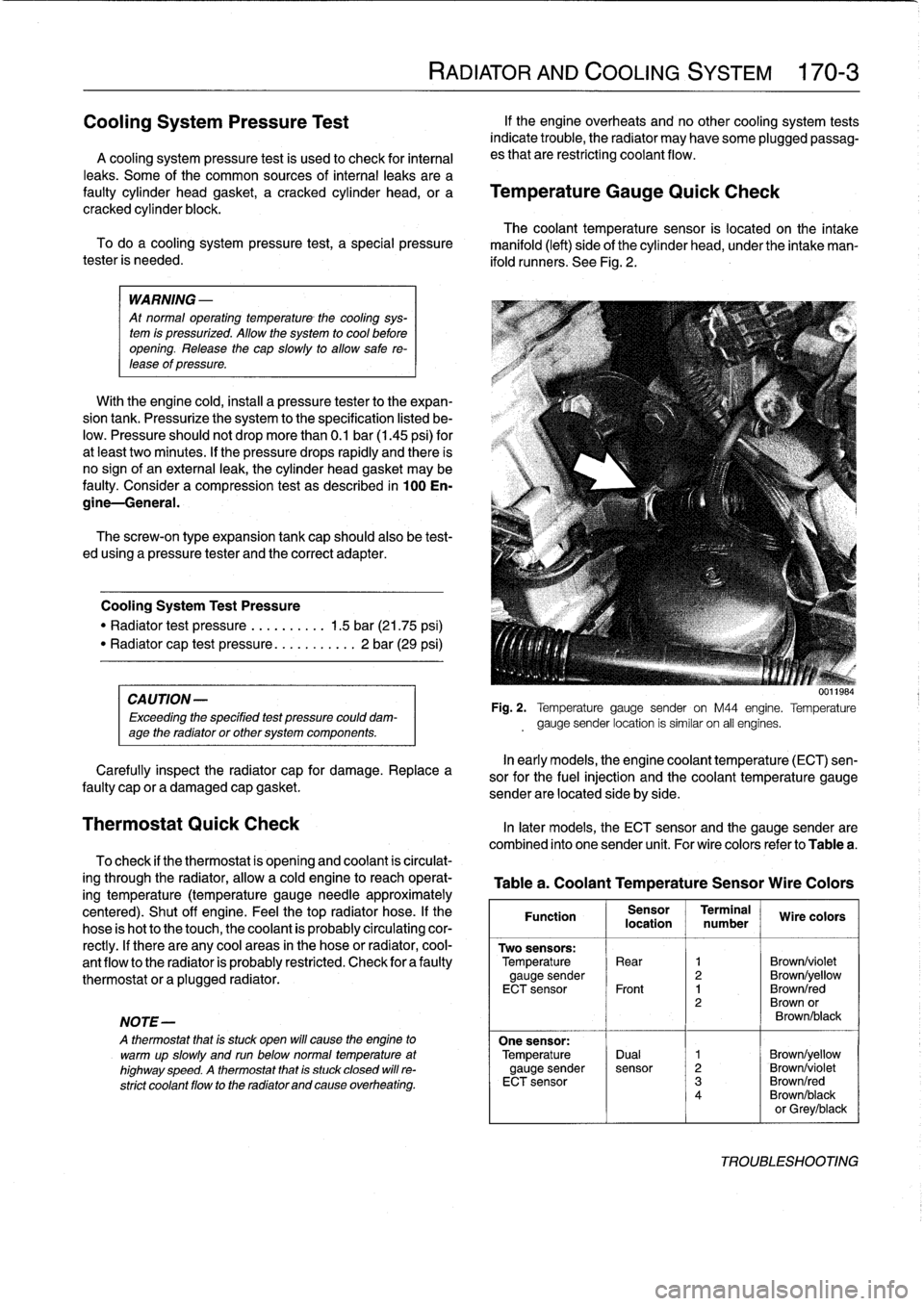
Temperature
Gauge
Quick
Check
cracked
cylinder
block
.
The
coolant
temperature
sensor
is
located
on
the
intake
To
doa
cooling
system
pressure
test,
a
special
pressure
manifold
(left)
side
of
the
cylinder
head,
under
the
intake
man-
tester
is
needed
.
ifold
runners
.
See
Fig
.
2
.
WARNING
-
At
normal
operating
temperature
-
the
cooling
sys-
tem
is
pressurized
.
Allow
the
system
to
cool
before
opening
.
Release
the
cap
slowly
to
allow
sale
re-
tease
of
pressure
.
With
the
engine
cold,instan
a
pressure
tester
to
the
expan-
sion
tank
.
Pressurize
thesystem
to
the
specification
listed
be-
low
.
Pressure
should
not
drop
more
than
0
.1
bar
(1
.45
psi)
for
at
leakt
two
minutes
.
If
the
pressure
drops
rapidly
and
there
is
no
sign
of
an
externa¡
leak,
the
cylinder
head
gasket
may
be
faulty
.
Considera
compression
test
as
described
in
100
En-
gine-General
.
The
screw-on
type
expansion
tank
cap
should
also
be
test-
ed
using
a
pressure
tester
and
the
correct
adapter
.
Cooling
System
Test
Pressure
"
Radiator
test
pressure
.........
.
1
.5
bar
(21
.75
psi)
"
Radiator
cap
test
pressure
..
.
........
2
bar
(29
psi)
CA
UTION-
Exceeding
the
speclfied
test
pressure
could
dam-
age
the
radiatoror
other
system
components
.
Carefully
inspect
the
radiator
cap
for
damage
.
Replace
a
faulty
cap
or
a
damaged
cap
gasket
.
Thermostat
Quick
Check
In
later
models,
the
ECT
sensor
and
the
gauge
sender
are
combined
into
one
sender
unit
.
For
wire
colors
refer
to
Table
a
.
To
check
if
the
thermostat
is
opening
and
coolant
is
circulat-
ing
through
the
radiator,
allow
a
cold
engine
to
reach
operat-
ing
temperature
(temperature
gauge
needieapproximately
centered)
.
Shut
off
engine
.
Feel
the
top
radiator
hose
.
If
the
hose
is
hot
to
the
touch,
the
coolant
is
probably
circulating
cor-
rectly
.
If
there
are
any
cool
areas
in
the
hose
or
radiator,
cool-
ant
flow
to
the
radiator
is
probably
restricted
.
Check
for
a
faulty
thermostat
or
aplugged
radiator
.
NOTE-
A
thermostat
that
is
stuck
open
will
cause
the
engine
to
warmup
slowly
and
run
belownormal
temperature
at
highway
speed
.
A
thermostat
that
is
stuck
closed
will
re-
strict
coolant
flow
to
the
radiator
and
cause
overheating
.
RADIATOR
AND
COOLING
SYSTEM
170-
3
U
.¡ig
.v
Fig
.
2
.
Temperature
gauge
sender
on
M44
engine
.
Temperature
gauge
sender
location
is
similar
on
al]
engines
.
In
early
models,
the
engine
coolant
temperature
(ECT)
sen-
sor
for
the
fuel
injection
and
the
coolant
temperature
gauge
sender
are
located
side
by
side
.
Table
a
.
Coolant
Temperature
Sensor
Wire
Colors
Function
Sensor
Terminal
Wire
colors
location
number
Two
sensors
:
Temperature
Rear
1
Brown/violet
gauge
sender
2
Brown/yellow
ECT
sensor
Front
1
Brown/red
2
Brown
or
Brown/black
One
sensor
:
Temperature
Dual
1
Brown/yellow
gauge
sender
sensor
2
Brown/violet
ECT
sensor
3
Brown/red
4
Brown/black
or
Grey/black
TROUBLESHOOTING
Page 198 of 759
170-
4
RADIATOR
AND
COOLING
SYSTEM
A
quick
testat
the
coolant
temperature
gauge
sender
can
The
auxiliary
cooling
fan
comes
on
when
coolant
tempera
determine
if
the
gauge
is
functioning
correctly
.
ture
exceeds
a
predetermined
leve¡
or
whenever
the
air
condi-
tioning
is
on
.
A
dual-range
temperature
switch
for
cooling
fan
lf
the
gauge
needie
remains
at
the
rest
position
with
theen-
control
is
mounted
on
the
right
side
of
the
radiator
.
See
Fig
.
3
.
gine
warm,
remove
the
harness
connector
from
the
sender
and
jumper
the
correct
terminals
in
the
connector
to
simulate
a
high
engine
temperature
.
See
Table
a
.
Turn
the
ignition
on
.
If
the
gauge
needle
moves
upward,
the
sender
is
faulty
.
If
the
gauge
does
not
respond,
the
wiring
to
the
gauge
is
broken
(open
circuit)
or
the
gauge
itselfis
faulty
.
WARNING
-
1996
and
laten
models
are
OBD
11
compliant
.
Dis-
connecting
electrical
connectors
wíth
the
ignition
turned
on
may
set
fault
codes
in
the
ECM
.
It
is
rec-
ommended
that
you
leave
the
diagnosis
of
faults
in
the
coolant
temperature
sensorsystem
to
the
BMW
dealer
service
department
which
has
specialized
OBD
11
scan
tool
equipment
.
If
the
gauge
needle
reads
too
high
when
the
engine
is
cold,
remove
the
harness
connector
from
the
sender
.
Turn
the
igni-
tion
on
.
lf
the
gauge
needle
position
does
not
change,
the
wir-
ing
or
the
gauge
is
shorted
to
ground
.
If
the
gauge
needle
drops,
the
sender
is
faulty
and
should
be
replaced
.
When
re-
placing
a
faulty
coolant
temperature
sender,
the
gasket
ring
on
the
sender
should
also
be
replaced
.
Tightening
Torque
"
Temperature
gauge
sender
to
engine
18
Nm
(13
ft-Ib)
Cooling
fan,
testing
NOTE-
OnM44
engines
with
manual
transmission,
the
primary
electric
cooling
fan
is
mounted
on
the
engine
side
of
the
radiator
and
is
controlled
by
the
engine
control
module
(ECM)
.
Troubleshooting
thiscircuit
should
be
left
to
an
authorized
BMW
dealer
with
the
proper
diagnostic
equipment
An
otherwise
sound
cooling
system
may
still
overheat,
par-
ticularly
with
prolonged
idling,
due
to
a
failure
of
the
coolíng
fan(s)
.
The
belt-driven
cooling
fan
is
controlled
by
a
temperature
dependent
viscous
clutch
.
A
failed
fan
clutch
may
affect
air
flow
through
the
radiator
resulting
in
overheating
orpossibly
overcooling
.
Speed
Low
sp
High
s
With
the
engine
off,
check
thefan
clutch
by
spinning
thefan
.
eed
The
fan
should
spin
on
the
clutch
with
some
resistance
.
peed
Check
for
signs
of
leaking
fluid
from
the
clutch
.
If
thefan
free-
wheels
with
no
resistance,
cannot
be
tu
rned
by
hand,
or
there
are
signs
of
oil
leakage,
the
clutch
should
be
replaced
.
TROUBLESHOOTING
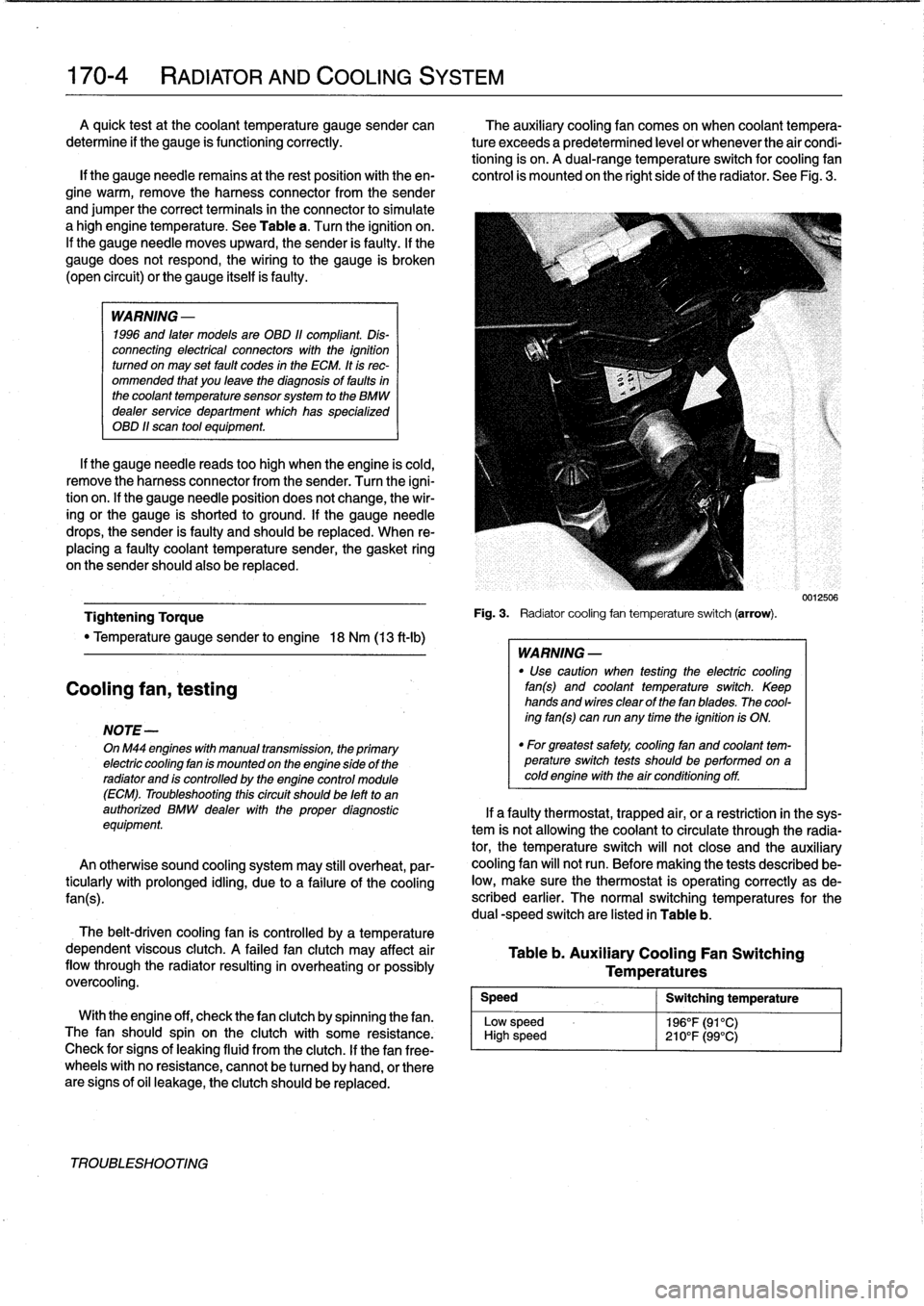
Fig
.
3
.
Radiatorcooling
fan
temperature
switch
(arrow)
.
WARNING
-
"
Use
caution
when
testing
the
electric
cooling
fan(s)
and
coolant
temperature
switch
.
Keep
hands
and
wires
clear
of
thefan
blades
.
The
cool-
ing
fan(s)
can
run
any
time
the
ignition
is
ON
.
"
For
greatest
safety,
coolíng
fan
and
coolant
tem-perature
switch
tests
shouldbe
performed
on
acoldengine
with
the
air
conditioning
off
.
Table
b
.
Auxiliary
Cooling
Fan
Switching
Temperatures
Switching
temperature
196°F(91°C)
210°F(99°C)
0012506
If
a
faulty
thermostat,
trapped
air,
or
a
restriction
in
the
sys-
tem
is
not
allowing
the
coolant
to
circulate
through
the
radia-
tor,
the
temperature
switch
will
not
close
and
the
auxiliary
cooling
fan
will
not
run
.
Before
making
the
tests
described
be-
low,
make
sure
the
thermostat
is
operating
correctly
as
de-
scribed
earlier
.
The
normal
switching
temperatures
for
the
dual
-speed
switch
are
listed
in
Table
b
.
Page 204 of 759
170-10
RADIATOR
AND
COOLING
SYSTEM
Coolant
pump,
replacing
The
engine
coolant
pump
is
mounted
in
the
frontof
the
en-
gine
on
the
timing
cover
.
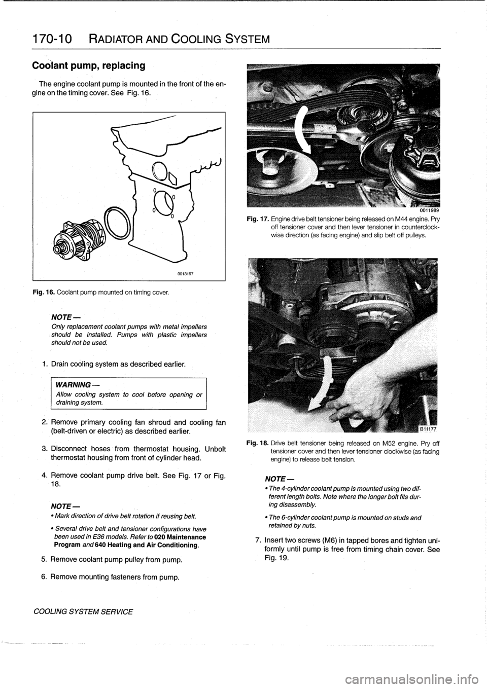
See
Fig
.
16
.
Fig
.
16
.
Coolant
pump
mounted
on
timing
cover
.
NOTE-
Onlyreplacement
coolant
pumps
with
metal
¡mpellers
should
be
installed
.
Pumps
with
plastic
impellers
should
not
be
used
.
1.
Drain
cooling
system
as
described
earlier
.
0013197
WARNING
-
Allow
cool¡ng
system
to
cool
before
open¡ngor
drain¡ng
system
.
2
.
Remove
primary
cooling
fan
shroud
and
cooling
fan
(belt-driven
or
electric)
as
described
earlier
.
Fig
.
17
.
Engine
drive
belt
tensioner
being
released
on
M44
engine
.
Pry
off
tensioner
cover
and
then
lever
tensioner
in
counterciock-
wise
direction
(as
facing
engine)
and
slip
belt
off
pulleys
.
Fig
.
18
.
Drive
belt
tensioner
being
released
on
M52
engine
.
Pry
off
3
.
Disconnect
hoses
from
thermostat
housing
.
Unbolt
tensioner
cover
and
then
lever
tensioner
clockwise
(as
facing
thermostat
housing
from
front
of
cylinder
head
.
engine)torelease
belt
tension
.
4
.
Remove
coolant
pump
drive
belt
.
See
Fig
.
17
or
Fig
.
18
.
NOTE-
-
Mark
direction
of
drive
belt
rotation
if
reusing
belt
.
"
The
6-cylinder
coolant
pump
¡s
mounted
on
studs
and
retained
by
nuts
.
"
Severa¡
drive
belt
and
tensioner
configurations
havebeenused
in
E36
models
.
Refer
to
020
Maintenance
Program
and
640
Heating
and
Air
Conditioning
.
5
.
Remove
coolant
pump
pulley
from
pump
.
6
.
Remove
mounting
fasteners
from
pump
.
COOLING
SYSTEM
SERVICE
NOTE-
"
The
4-cylinder
coolant
pump
¡s
mounted
us¡ng
two
dif-
terent
length
bolts
.
Note
where
thelonger
bolt
fits
dur-
ing
disassembly
.
0011989
7
.
Insert
twoscrews
(M6)
in
tapped
bores
and
tighten
uni-
formly
until
pump
is
free
from
timing
chain
cover
.
See
Fig
.
19
.
Page 224 of 759
230-
4
MANUAL
TRANSMISSION
Output
shaft
sea¡,
replacing
(transmission
installed)
1
.
Raise
and
safely
support
vehicle
.
Support
transmission
with
transmission
jack
.
WARNING
-
"
When
raising
thecar
using
a
floor
jack
or
a
hy-
draulic
lift,
carefully
position
the
jack
pad
to
pre-vent
damaging
the
car
body
.
A
suitable
liner
(wood,
rubber,
etc
.)
should
be
placed
between
the
jack
and
the
car
to
prevent
body
damage
.
"
Watch
the
jack
closely
.
Make
sure
it
stays
stable
and
does
not
shift
or
tilt
.
As
the
car
is
raised,
the
car
may
roll
slightly
and
the
jack
may
shift
.
2
.
Remove
driveshaft
.
See
260
Driveshaft
.
3
.
Remove
transmission
crossmember
and
lower
trans-
mission
at
rear
.
CAUTION-
Tilting
the
engine
to
lower
thetransmissíon
can
lead
to
damage
to
various
componente
due
to
lackof
clearance
.
-On
cars
with
AST
(traction
control)
remove
throt-
tle
body
before
tilting
engine
.
-Remove
brake
fluid
reservoir
if
necessary
.
4
.
Bend
back
and
remove
collar
nut
lockplate
.
5
.
Hold
flange
steady
andremove
collar
lock
nut
(use
30mm
thin-walled
deep
socket
.)
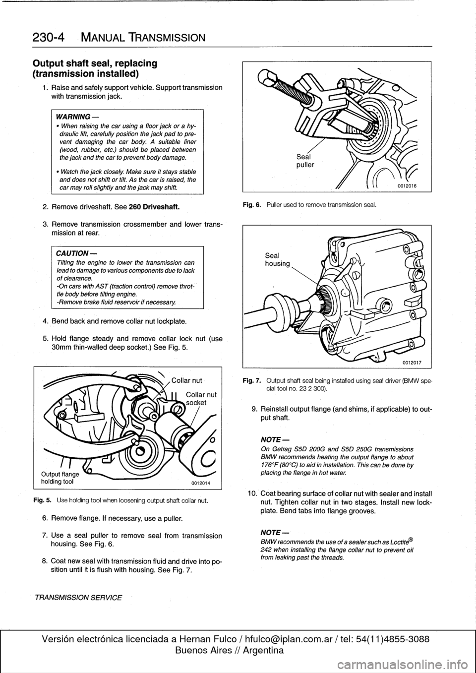
See
Fig
.
5
.
Fig
.
5
.
Use
holding
tool
when
loosening
output
shaft
collar
nut
.
6
.
Remove
flange
.
If
necessary,
use
a
puller
.
7
.
Use
a
sea¡
puller
to
remove
seal
from
transmission
housing
.
See
Fig
.
6
.
8
.
Coat
new
sea¡
wíth
transmission
fluid
and
drive
into
po-
sition
until
it
is
flush
with
housing
.
See
Fig
.
7
.
TRANSMISSIONSERVICE
Fig
.
6
.
Puller
used
to
remove
transmission
seal
.
Fig
.
7
.
Output
shaftseal
being
installed
using
seal
driver
(BMW
spe-
cial
tool
no
.
232
300)
.
9
.
Reinstall
output
flange
(and
shims,
if
applicable)
to
out-
put
shaft
.
NOTE-
On
Getrag
S5D200G
and
S5D
250G
transmissions
BMW
recommends
heating
theoutputflange
to
about
176°F
(80°C)
to
aid
in
installation
.
This
canbe
done
by
placing
the
flange
in
hot
water
.
10
.
Coat
bearingsurface
ofcollar
nut
withsealer
and
install
nut
.
Tighten
collar
nut
in
two
stages
.
Insta¡¡
new
lock-
plate
.
Bend
tabs
into
flange
grooves
.
NOTE-
BMW
recommends
the
use
of
a
sealer
such
as
Loctite
®
242
when
installing
the
flange
collar
nut
to
prevent
oil
from
leaking
past
the
threads
.
Page 280 of 759
330-
8
REAR
SUSPENSION
CV
boot,
replacing
NOTE-
"
The
outer
CV
joint
cannot
be
removed
from
the
axle
shaft
.
In
order
to
replace
the
outer
CV
boot,
it
is
nec-
essary
to
remove
the
inner
joint
and
boot
first
.
"
If
the
CV
joints
are
worn
or
defective,
acomplete
re-
built
axle
shaft
is
available
from
an
authorized
BMW
dealerparts
department
.
1
.
Remove
drive
axle
from
car
as
described
above
.
2
.
Remove
inner
and
outer
CV
boot
clamping
bands
and
cut
old
boots
off
joints
and
shaft
.
Clean
grease
from
joints
.
3
.
Lift
off
dust
cover
from
inner
CV
joint
and
remove
circlip
5
.
Clean
all
old
lubricantoff
shaftsplines
and
inner
joint's
retaining
joint
inner
hub
to
axle
shaft
.
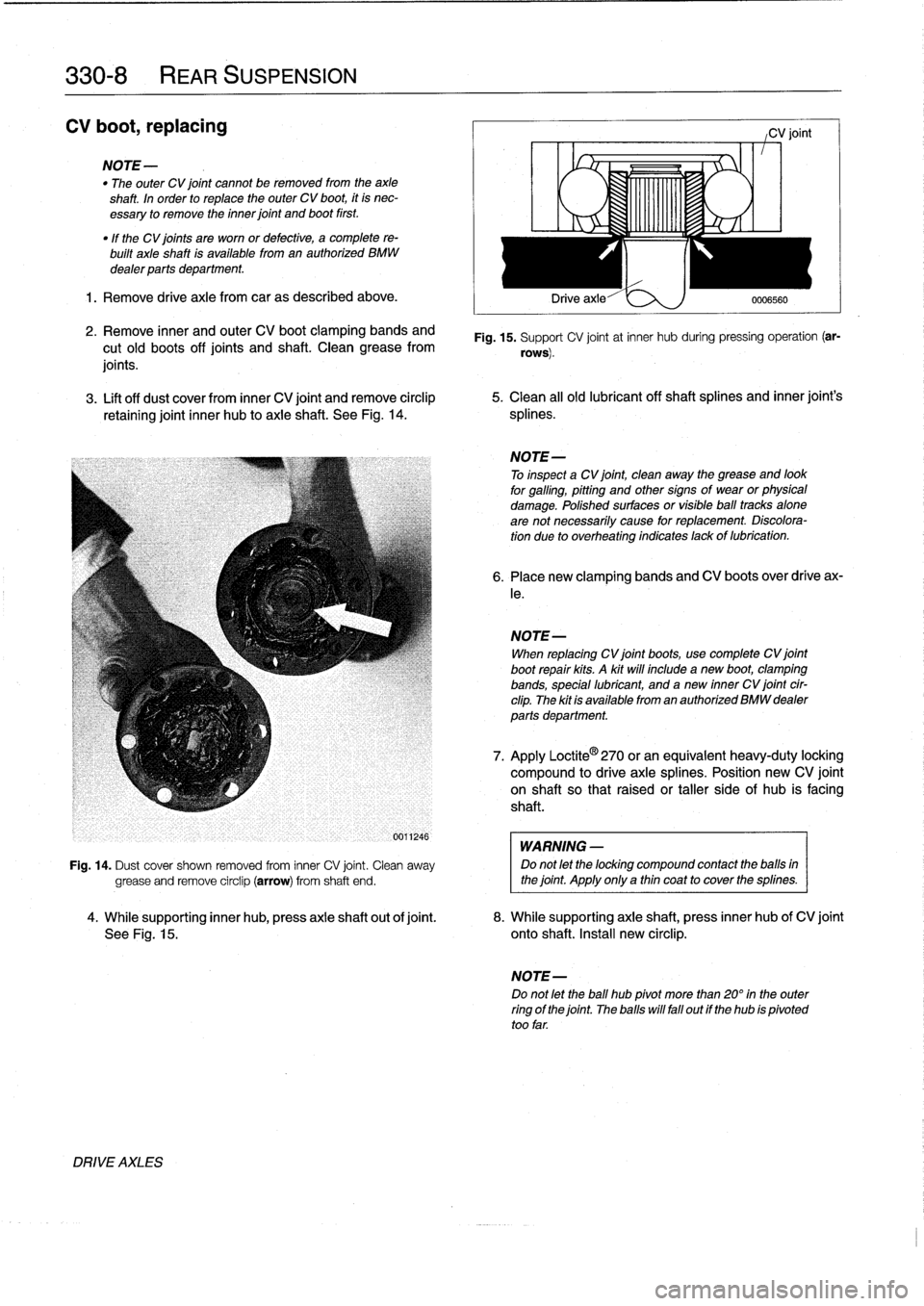
See
Fig
.
14
.
splines
.
DRIVE
AXLES
-0
1
,
1
1,1
1
L
"I
C
OYA
Drive
axle-"
e
:>,
)
0006560
CV
joint
Fig
.
15
.
Support
CV
joint
at
inner
hub
duringpressing
operation
(ar-
rows)
.
NOTE-
To
inspect
a
CV
joint,
clean
away
the
grease
and
look
for
galling,pittihg
and
othersigns
of
wear
or
physical
damage
.
Polished
surfaces
or
visible
ball
tracks
alone
are
not
necessarily
cause
for
replacement
.
Discolora-
tion
due
to
overheating
indicates
lackof
lubrication
.
6
.
Place
new
clamping
bands
and
CV
boots
over
drive
ax-
le
.
NOTE-
When
replacing
CV
joint
boots,
usecomplete
CV
joint
boot
repair
kits
.
A
kit
will
include
a
new
boot,
clamping
bands,
special
lubricant,
and
anew
inner
CV
joint
cir-
clip
.
The
kit
is
available
from
an
authorized
BMW
dealer
parts
department
.
7
.
Apply
Loctite
®
270
or
an
equívalent
heavy-duty
lockíng
compound
to
drive
axlesplines
.
Position
new
CV
joint
on
shaft
so
that
raisedor
taller
side
of
hub
is
facing
shaft
.
WARNING
-
Fig
.
14
.
Dust
cover
shown
removed
from
inner
CV
joint
.
Clean
away
Do
not
let
the
locking
compound
contact
the
balls
in
grease
and
remove
circlip
(arrow)
from
shaft
end
.
the
joint
.
Apply
only
a
thin
coat
to
cover
the
splines
.
4
.
While
supporting
inner
hub,
press
axle
shaft
out
of
joint
.
8
.
While
supporting
axle
shaft,
press
inner
hub
of
CV
joint
See
Fig
.
15
.
onto
shaft
.
Install
new
circlip
.
NOTE-
Do
not
let
the
ball
hub
pivot
more
than
20°
in
the
outer
ring
of
the
joint
.
The
halls
will
fall
out
if
the
hub
ís
pivoted
too
far
.