horn BMW 328i 1995 E36 User Guide
[x] Cancel search | Manufacturer: BMW, Model Year: 1995, Model line: 328i, Model: BMW 328i 1995 E36Pages: 759
Page 410 of 759
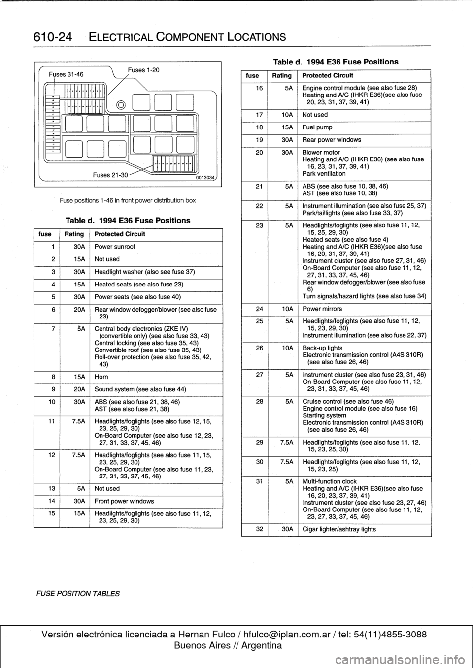
610-24
ELECTRICAL
COMPONENT
LOCATIONS
Fuses
31-46
v
-
-----------
Fuses
21-30
Fuses1-20
Fuse
positions
1-46
infront
power
distribution
box
Tabled
.
1994
E36
Fuse
Positions
fuse
Rating
Protected
Circuit
1
30A
Power
sunroof
2
15A
Not
used
3
30A
Headlight
washer
(also
see
f
use
37)
4
15A
Heated
seats
(seealsofuse
23)
5
30A
Power
seats
(seealso
f
use
40)
6
20A
Rear
window
defogger/blower(see
also
f
use
23)
7
$A
Central
body
electronics
(ZKE
IV)
(convertible
only)
(see
also
fuse
33,
43)
Central
locking
(seealso
fuse
35,
43)
Convertible
roof
(seealsofuse
35,43)
Rol¡-over
protection
(seealso
f
use
35,
42,
43)
8
I
15A
I
Horn
9
(
20A
1
Sound
system
(see
also
fuse
44)
10
I
30A
ABS
(see
also
fuse
21,38,
46)
AST
(seealso
f
use
21,
38)
11
7
.5A
Headlights/foglights
(see
also
fuse
12,15,23,25,29,
30)
On-Board
Computer
(see
alsofuse
12,23,27,31,33,37,
45,46)
12
7.5A
Headlights/foglights
(see
also
fuse
11,15,23,25,29,
30)
On-Board
Computer
(see
alsofuse
11,23,
27,
31,33,37,
45,46)
13
I
5A
I
Not
used
14
1
30A
1
Front
power
windows
0013034
15
15A
Headlights/foglights
(see
also
fuse
11,12,
23,
25,29,
30)
FOSE
POSITION
TABLES
Table
d
.
1994
E36
Fuse
Positions
fuse
1
Rating
1
Protected
Circuit
16
5A
~
Engine
control
module
(see
also
f
use
28)
Heating
andA/C
(IHKR
E36)(see
alsofuse
20,
23,
31,37,
39,41)
17
I
10A
I
Not
used
18
1
15A
1
Fuel
pump
19
1
30A
1
Rear
power
windows
20
30A
Blowermotor
Heating
and
A/C
(IHKR
E36)
(see
also
fuse
16,23,31,
37,39,41)
Park
ventilation
21
5A
ABS
(seealsofuse
10,38,
46)
AST
(see
also
fuse
10,
38)
22
5A
Instrument
illumination
(see
also
f
use
25,
37)
Park/taillights
(see
also
fuse
33,
37)
23
5A
Headlights/foglights
(see
alsofuse
11,12,15,25,
29,30)
Heated
seats
(seealsofuse
4)
Heating
andA/C
(IHKR
E36)(see
alsofuse
16,20,31,
37,
39,
41)
Instrument
cluster
(see
also
f
use
27,31,
46)
On-Board
Computer
(see
also
f
use
11,
12,
27,
31,
33,37,
45,
46)
Rear
window
defogger/blower
(see
alsofuse
6)
Turn
signais/hazard
lights
(see
alsofuse
34)
24
I
10A
I
Power
mirrors
25
5A
~
Headlights/foglights
(see
also
fuse
11,12,15,23,
29,30)
Instrument
illumination
(see
also
fuse
22,
37)
26
10A
~
Back-up
lights
Electronic
transmission
control
(A4S
310R)
(seealso
f
use
26,
46)
27
5A
~
Instrument
cluster
(see
also
fuse
23,
31,46)
On-BoardComputer
(see
also
f
use
11,12,23,31,
33,37,
45,
46)
28
5A
Cruise
control
(see
also
fuse
46)
Engine
control
module
(see
alsofuse
16)
Starting
system
Electronic
transmission
control
(A4S
310R)
(seealsofuse
26,46)
29
7
.5A
Headlights/foglights
(seealsofuse
11,12,15,23,
25,30)
30
7.5A
Headlights/foglights
(seealsofuse
11,12,15,23,
25)
31
5A
Multi-function
clock
Heating
andA/C
(IHKR
E36)(see
alsofuse
16,20,
23,
37,39,
41)
Instrument
cluster
(see
also
fuse
23,27,46)
On-Board
Computer
(see
also
fuse
11,
12,
23,27,
33,
37,45,
46)
32
1
30A
1
Cigar
lighterlashtray
lights
Page 412 of 759
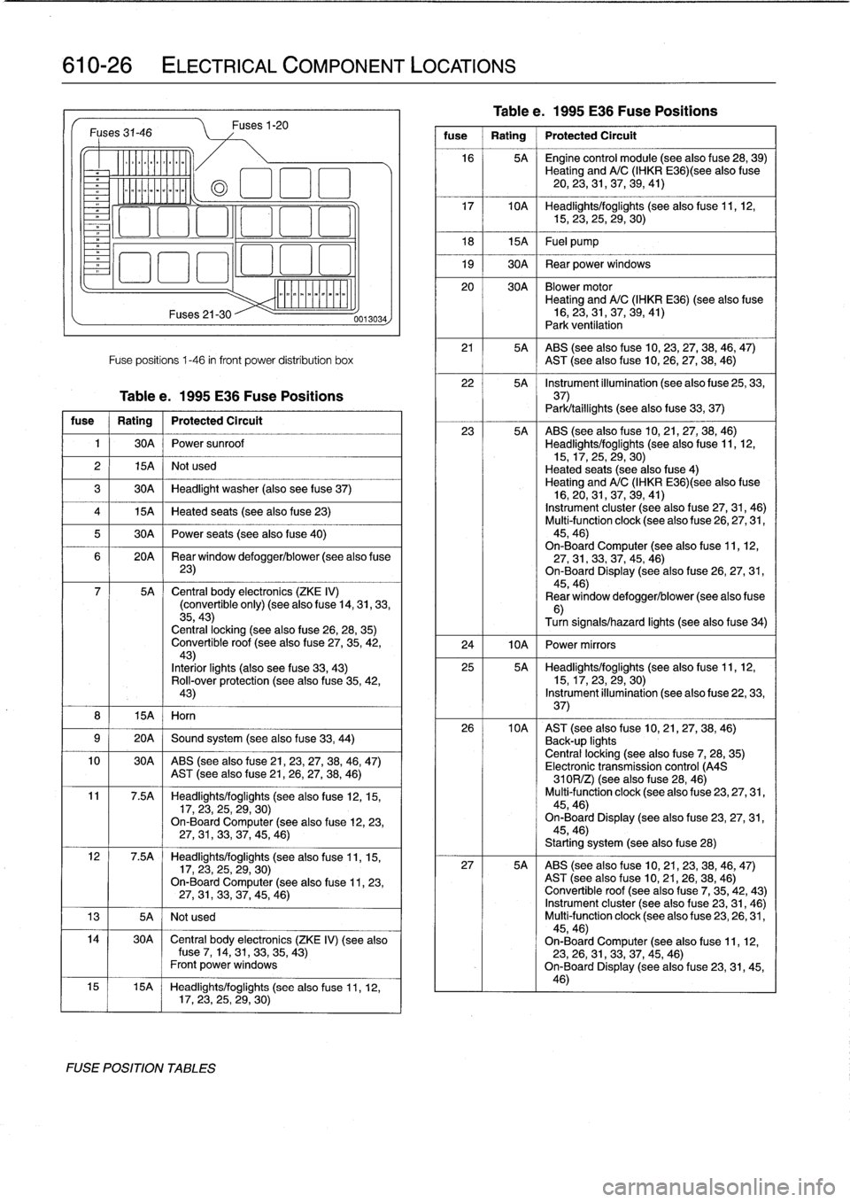
610-26
ELECTRICAL
COMPONENT
LOCATIONS
Fuses31-46
v
.
-------------
Fuses
21-30
Fuses1-20
Fuse
positions
1-46
in
front
power
distribution
box
Tablee
.
1995
E36
Fuse
Positions
fuse
Rating
Protected
Circuit
1
30A
Power
sunroof
2
15A
Not
used
3
30A
Headlight
washer
(also
see
f
use
37)
4
15A
Heated
seats
(see
alsofuse
23)
5
30A
Power
seats
(see
alsofuse
40)
6
20A
Rear
window
defogger/blower(see
also
f
use
23)
7
5A
Central
body
electronics
(ZKE
IV)
(convertible
only)
(see
also
fuse
14,31,33,
35,43)
Centrallocking
(see
also
fuse
26,28,
35)
Convertible
roof
(see
also
fuse
27,
35,
42,43)
Interiorlights
(also
see
fuse
33,
43)
Roll-over
protection
(seealsofuse
35,42,
43)
8
I
15A
I
Horn
9
1
20A
1
Sound
system
(seealsofuse
33,
44)
0013034
10
30A
ABS
(seealsofuse
21,23,
27,
38,46,
47)
AST
(see
also
fuse
21,
26,27,38,
46)
11
7
.5A
Headlights/foglights
(see
also
fuse
12,
15,
17,
23,
25,29,
30)
On-Board
Computer
(seealsofuse
12,23,27,
31,
33,37,45,
46)
12
7
.5A
Headlights/foglights
(see
also
fuse
11,
15,
17,
23,25,
29,
30)
On-BoardComputer
(see
also
fuse
11,
23,27,
31,
33,37,45,
46)
13
I
5A
I
Notused
14
30A
~
Central
body
electronics
(ZKE
IV)
(see
alsofuse
7,
14,31,
33,
35,
43)
Front
power
Windows
15
15A
Headlights/foglights
(seealso
fuse
11,
12,
17,23,25,
29,30)
FOSE
POSITION
TABLES
Tablee
.
1995
E36
Fuse
Positions
fuse
1
Rating
1
Protected
Circuit
16
5A
~
Engine
control
module
(see
also
f
use
28,39)
Heating
andA/C
(IHKR
E36)(see
alsofuse
20,
23,31,
37,
39,
41)
17
10A
Headlights/foglights
(see
also
fuse
11,12,15,23,25,
29,
30)
18
1
15A
1
Fuel
pump
19
1
30A
1
Rear
power
Windows
20
30A
Blowermotor
Heating
andA/C
(IHKR
E36)
(see
also
fuse
16,23,31,
37,
39,
41)
Park
ventilation
21
5A
ABS
(seealsofuse
10,23,27,38,
46,47)
AST
(see
also
fuse
10,26,
27,
38,
46)
22
5A
~
Instrument
illumination
(see
also
f
use
25,
33,37)
Park/taillights
(see
also
fuse
33,
37)
23
5A
ABS
(seealsofuse
10,
21,
27,38,
46)
Headlights/foglights
(see
also
fuse
11,12,15,17,25,
29,
30)
Heated
seats
(see
also
fuse
4)
Heating
andA/C
(IHKR
E36)(see
alsofuse
16,20,31,
37,39,41)
Instrument
cluster
(see
also
f
use
27,31,
46)
Multi-function
clock
(see
also
fuse
26,27,31,
45,46)
On-Board
Computer
(seealso
f
use
11,
12,
27,
31,33,
37,
45,
46)
On-Board
Display
(seealso
fuse
26,27,31,
45,46)
Rear
window
defogger/blower
(see
also
f
use
6)
Turn
signals/hazard
lights
(see
also
f
use
34)
24
I
10A
I
Power
mirrors
25
5A
Headlights/foglights
(see
also
fuse
11,
12,
15,17,23,
29,
30)
Instrument
illumination
(see
also
fuse
22,33,
37)
26
10A
AST
(see
also
fuse
10,21,
27,
38,
46)
Back-up
lights
Centrallocking
(seealsofuse
7,
28,
35)
Electronic
transmission
control
(A4S
310R/Z)
(seealso
tuse
28,
46)
Multi-function
clock
(see
also
fuse
23,
27,31,
45,46)
On-Board
Display
(see
also
fuse
23,27,31,
45,46)
Starting
system
(see
alsofuse
28)
27
5A
ABS
(seealso
fuse
10,
21,
23,38,
46,47)
AST
(see
also
fuse
10,21,
26,
38,
46)
Convertible
roof
(see
also
f
use
7,
35,42,43)
Instrument
cluster
(seealso
f
use
23,
31,
46)
Multi-function
clock
(see
also
fuse
23,26,31,
45,46)
On-Board
Computer
(seealsofuse
11,
12,
23,
26,
31,33,
37,
45,
46)
On-Board
Display
(see
also
f
use
23,31,45,
46)
Page 414 of 759
![BMW 328i 1995 E36 User Guide
610-28
ELECTRICAL
COMPONENT
LOCATIONS
Fuses
31-46
k
Lírcoo)]
LE
7a
Maz
Fuses
21-30
Fuse
positions
1-46
in
front
power
distribution
box
Table
f
.
1996
E36
Fuse
Positions
fuse
Rating
BMW 328i 1995 E36 User Guide
610-28
ELECTRICAL
COMPONENT
LOCATIONS
Fuses
31-46
k
Lírcoo)]
LE
7a
Maz
Fuses
21-30
Fuse
positions
1-46
in
front
power
distribution
box
Table
f
.
1996
E36
Fuse
Positions
fuse
Rating](/img/1/2800/w960_2800-413.png)
610-28
ELECTRICAL
COMPONENT
LOCATIONS
Fuses
31-46
k
Lírcoo)]
LE
7a
Maz
Fuses
21-30
Fuse
positions
1-46
in
front
power
distribution
box
Table
f
.
1996
E36
Fuse
Positions
fuse
Rating
Protected
Circuit
1
30A
Power
sunroof
(see
also
fuse
13)
2
15A
Notused
3
30A
Headlight
washer
(also
see
fuse
37)
4
15A
Heated
seats
(seealsofuse
23)
5
30A
Power
seats
(see
also
f
use
40)
6
20A
Rear
window
defogger/blower
(see
also
f
use
23)
7
5A
Central
body
electronics
(ZKE
IV)
(convertible
only)
(see
also
f
use
14,33,
35,
43)
Central
locking
(seealso
fuse
26,28,
35)
Convertible
roof
(seealsofuse
27,35,42,43)
Interiorlights
(also
see
fuse
33,
43)
Rol¡-oven
protection
(see
also
fuse
35,
42,
43)
8
I
15A
I
Horn
9
1
20A
1
Sound
system
(see
also
fuse
44)
10
30A
ABS
(seealsofuse
21,23,
27,38,46,
47)
AST
(see
also
fuse
21,26,27,
38,46)
11
7.5A
Headlights/foglights
(see
also
fuse
12,15,17,23,25,
29,30)
On-Board
Computer
(seealso
fuse
12,23,27,31,33,
37,45,46)
12
7
.5A
Headlights/foglights
(see
also
fuse
11,15,17,
23,
25,
29,30)
On-Board
Computer
(see
also
f
use
11,23,27,
31,
33,37,
45,46)
13
1
5A
1
Power
sunroof
(seealsofuse
1)
14
30A
~
Central
body
electronics
(ZKE
IV)
(see
also
fuse
7,
14,33,35,
43)
Front
power
windows
15
15A
Headlights/foglights
(see
also
fuse
11,12,17,23,25,29,
30)
FUSE
POSITION
TABLES
Fuses
1-20
0013034
Table
f
.
1996
E36
Fuse
Positions
fuse
1
Rating
1
Protected
Circult
16
5A
~
Engine
control
module
(see
also
f
use
28,
39)
Heating
andA/C
(IHKR
E36)(see
also
fuse
20,
23,31,37,39,41,
48)
17
10A
Headlights/foglights
(see
also
f
use
11,12,
15,23,25,29,
30)
18
1
15A
1
Fuel
pump
19
1
30A
1
Rear
power
windows
20
30A
Blower
motor
Heating
andA/C
(IHKR
E36)
(see
also
fuse
16,23,31,37,39,41,
48)
Park
ventilatíon
21
5A
ABS
(seealsofuse
10,23,
27,38,
46,
47)
AST
(see
alsofuse
10,
26,
27,38,
46)
22
5A
Instrument
illumínation
(see
also
f
use
25,33,
37)
23
5A
ABS
(see
also
fuse
10,21,
27,38,
46)
Headlights/foglights
(see
alsofuse
11,12,
15,17,25,29,
30)
Heated
seats
(seealsofuse
4)
Heating
andA/C
(IHKR
E36)(see
also
fuse
16,20,
31,
37,39,
41,48)
Instrument
cluster
(see
alsofuse
27,
31,46)
Multi-function
clock
(see
alsofuse
26,27,31,
45,46)
On-BoardComputen
(seealso
f
use
11,12,27,31,
33,
37,45,
46)
On-Board
Display
(see
alsofuse
26,
27,31,
45,46)
Rear
window
defogger/blower
(see
also
fuse
6)
Turn
signals/hazard
lights
(seealsofuse
34)
24
I
10A
I
Power
mirrors
25
5A
Headlights/foglights
(see
also
fuse
11,
12,15,
17,
23,
29,
30)
Instrument
illumination
(seealso
fuse
22,
33,
37)
26
10A
Airbag
(SRS)
(see
also
fuse
43)
AST
(see
also
f
use
10,21,
27,
38,
46)
Back-up
lights
Central
locking
(seealsofuse
7,
28,
35)
Electronic
transmission
control
(A4S
310R/Z)
(seealso
f
use
28,
46)
Multi-function
clock
(see
alsofuse
23,27,31,
45,46)
On-Board
Display
(see
also
fuse
23,
27,
31,
45,46)
Starting
system
(see
also
fuse
28)
.
27
5A
ABS
(see
also
fuse
10,21,
23,38,
46,
47)
AST
(see
also
fuse
10,
21,
26,38,
46)
Convertible
roof
(see
also
f
use
7,
35,42,
43)
Instrument
cluster
(see
alsofuse
23,
31,46)
Multi-function
clock
(see
alsofuse
23,26,
31,
45,46)
On-Board
Computer
(seealsofuse
11,12,
23,
26,31,33,37,
45,46)
On-Board
Display
(see
also
fuse
23,
31,45,
46)
Page 416 of 759
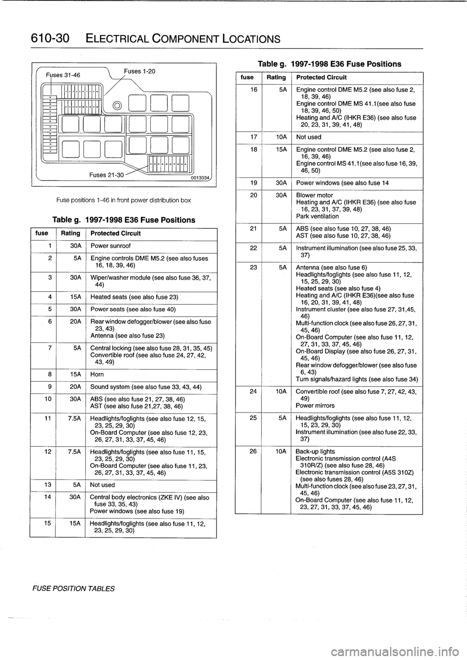
610-30
ELECTRICAL
COMPONENT
LOCATIONS
Fuses
31-46
v
--------------
15A
I
Horn
Fuses21-30
Fuses
1-20
Fuse
positions
1-46
in
front
power
distribution
box
Tableg
.
1997-1998
E36
Fuse
Positions
fuse
Rating
Protected
Circuit
1
I
30A
I
Power
sunroof
4
1
15A
1
Heated
seats
(see
also
fuse
23)
5
1
30A
1
Power
seats
(see
also
fuse
40)
10
30A
ABS
(see
also
fuse
21,27,38,
46)
AST
(see
alsofuse21,27,
38,
46)
13
I
5A
I
Not
used
FUSE
POSITION
TABLES
0013034
2
I
5A
Engine
controls
DME
M5
.2
(see
also
fuses
16,18,
39,
46)
30A
Wiper/washer
module
(seealso
fuse
36,37,44)
20A
~
Rear
window
defogger/blower
(see
also
f
use23,43)
Antenna
(see
also
fuse
23)
5A
~
Central
locking
(seealso
fuse
28,31,35,
45)
Convertible
roof
(see
also
fuse
24,
27,42,
43,49)
9
1
20A
1
Sound
system
(see
also
fuse
33,43,
44)
11
7
.5A
Headlights/foglights
(see
also
fuse
12,15,
23,
25,29,
30)
On-Board
Computer
(see
also
fuse
12,23,
26,
27,31,33,
37,45,
46)
12
7
.5A
Headlights/foglights
(see
also
fuse
11,15,
23,
25,29,
30)
On-Board
Computer
(see
also
f
use
11,23,
26,27,
31,33,
37,45,
46)
14
I
30A
~
Central
body
electronics
(ZKE
IV)
(see
also
fuse
33,
35,43)
Power
windows
(seealso
f
use
19)
15
15A
Headlights/foglights
(see
alsofuse
11,
12,23,25,
29,
30)
Tableg
.
1997-1998
E36
Fuse
Positions
fuse
1
Rating
1
Protected
Circuit
16
5A
Engíne
control
DME
M5
.2
(see
alsofuse
2,
18,39,
46)
Engine
control
DME
MS
41
.1
(see
also
fuse
18,39,46,
50)
Heating
andA/C
(IHKR
E36)
(see
also
fuse
20,
23,31,39,41,
48)
17
I
10A
1
Not
used
18
15A
Engine
control
DME
M5
.2
(seealso
fuse
2,
16,39,
46)
Engine
control
MS
41.1(seealso
fuse
16,
39,
46,50)
19
1
30A
j
Power
windows
(seealsofuse
14
20
30A
Blowermotor
Heating
andA/C
(IHKR
E36)
(see
also
fuse
16,
23,
31,37,39,
48)
Park
ventilation
21
5A
ABS
(seealso
f
use
10,
27,38,
46)
AST
(see
also
fuse
10,27,38,
46)
22
5A
Instrument
illumination
(see
also
f
use
25,
33,
37)
23
5A
Antenna
(see
also
fuse
6)
Headlights/foglights
(see
also
fuse
11,
12,
15,
25,
29,
30)
Heated
seats
(see
also
fuse
4)
Heating
andA/C
(IHKR
E36)(see
also
fuse
16,
20,
31,39,41,
48)
Instrument
cluster
(seealso
f
use
27,
31,45,
46)
Multi-function
clock
(seealsofuse
26,27,31,
45,46)
On-Board
Computer
(see
also
fuse
11,12,27,
31,
33,37,45,
46)
On-Board
Display
(seealsofuse
26,27,
31,
45,46)
Rear
window
defogger/blower
(see
also
f
use6,43)Turn
signals/hazard
lights
(seealsofuse
34)
24
10A
~
Convertible
roof
(see
also
f
use
7,
27,42,43,
49)
Power
mirrors
25
5A
Headlights/foglights
(seealso
fuse
11,12,
15,23,
29,30)
Instrument
illumination
(seealso
fuse
22,33,
37)
26
10A
Back-up
lights
Electronic
transmission
control
(A4S
310R/Z)
(see
also
f
use
28,
46)
Electronic
transmission
control
(A5S
310Z)
(see
also
fuses
28,46)
Multi-function
clock
(see
also
fuse
23,
27,
31,
45,46)
On-Board
Computer
(see
alsofuse
11,
12,
23,
27,31,33,37,45,
46)
Page 437 of 759
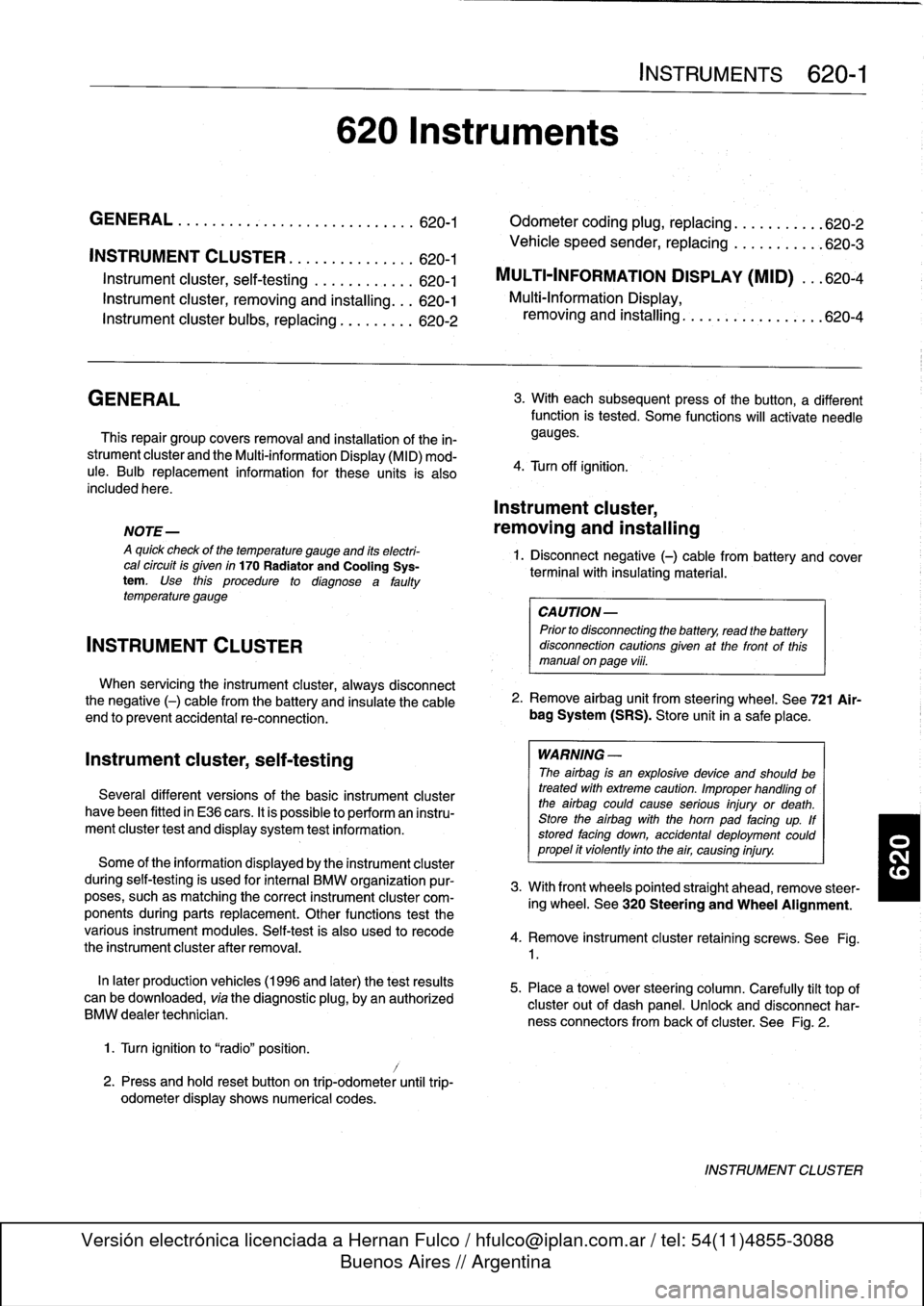
INSTRUMENT
CLUSTER
....
.
.
.
.
.
...
.
..
620-1
Instrument
cluster,
seif-testing
.
.
.......
.
..
620-1
Instrument
cluster,
removing
and
installing
...
620-1
Instrument
cluster
bulbs,
replacing
.
.
.
.
.
.
...
620-2
GENERAL
This
repair
group
covers
removal
and
installation
of
the
in-
strument
cluster
and
the
Multi-information
Display
(MID)
mod-
ule
.
Bulb
replacement
information
for
these
units
is
also
included
here
.
NOTE
-
A
quick
check
of
the
temperature
gauge
and
its
electri-
cal
circuitis
given
in
170
Radiator
and
Cooling
Sys-
tem
.
Use
this
procedure
to
diagnosea
faulty
temperature
gauge
INSTRUMENT
CLUSTER
When
servicing
the
instrument
cluster,
always
disconnect
the
negative
(-)
cable
from
the
battery
and
insulate
the
cable
end
to
prevent
accidental
re-connection
.
Instrument
cluster,
seif-testing
Severa¡
different
versions
of
the
basic
instrument
cluster
havebeen
fitted
in
E36
cars
.
It
is
possibleto
perform
an
instru-
ment
cluster
test
and
display
system
test
information
.
Some
of
the
information
displayed
by
the
instrument
cluster
during
seif-testing
is
used
for
interna¡
BMW
organizationpur-
poses,
suchasmatching
the
correct
instrument
cluster
com-
ponents
during
parts
replacement
.
Other
functions
test
the
various
instrument
modules
.
Self-test
is
also
used
to
recode
the
instrument
cluster
after
removal
.
In
later
production
vehicles
(1996
and
later)
the
test
results
canbe
downioaded,
via
the
diagnostic
plug,
byan
authorized
BMW
dealertechnician
.
1
.
Turn
ignition
to
"radio"position
.
2
.
Press
and
hold
reset
button
on
trip-odometer
untiltrip-
odometer
display
shows
numerical
codes
.
620
Instruments
4
.
Turn
off
ignition
.
Instrument
cluster,
removing
and
installing
INSTRUMENTS
620-1
GENERAL
.....
.
.
.
.
.
.
.
.
.
.........
.
....
620-1
Odometer
coding
plug,
replacing
.....
.
.
.
.
.
.
620-2
Vehicle
speed
sender,
replacing
...
.
.
.
.
.
.
.
.
620-3
MULTI-INFORMATION
DISPLAY
(MID)
.
.
.
620-4
Multi-Information
Display,
removing
and
installing
..
.
....
.
.........
620-4
3
.
With
each
subsequent
press
of
the
button,
a
different
function
is
tested
.
Some
functions
will
activate
need1e
gauges
.
1
.
Disconnect
negative
(-)
cable
from
battery
and
cover
terminal
with
insulating
material
.
CAUTION-
Prior
to
disconnectiog
the
battery,
read
the
battery
disconnection
cautionsgiven
at
the
front
of
this
manual
on
page
vi¡¡
.
2
.
Remove
airbag
unit
from
steering
wheel
.
See
721
Air-
bag
System
(SRS)
.
Store
unit
in
a
safe
place
.
WARNING
-
The
airbag
is
an
explosive
devfce
and
should
be
treated
with
extreme
caution
.
Improper
handling
of
the
airbag
could
cause
serious
injury
or
death
.
Store
the
airbag
with
the
horn
pad
facing
up
.
If
stored
facing
down,
accidental
deployment
couldpropel
it
vfolently
into
the
air,
causing
injury
.
3
.
With
front
wheels
pointed
straight
ahead,
remove
steer-
ing
wheel
.
See
320
Steering
and
Wheel
Alignment
.
4
.
Remove
instrument
cluster
retaining
screws
.
See
Fig
.
1
.
5
.
Place
a
towel
over
steering
column
.
Carefully
tilt
top
of
cluster
out
of
dash
panel
.
Unlock
and
disconnect
har-
ness
connectors
from
back
of
cluster
.
See
Fig
.
2
.
INSTRUMENT
CLUSTER
Page 479 of 759
1
.
Disconnect
negative
(-)
cable
from
battery
and
cover
negative
terminal
with
insulating
material
.
CA
UTION-
Prior
to
disconnectiog
the
battery,
read
the
battery
disconnection
cautions
given
at
the
front
of
this
manual
on
page
viii
.
2
.
Remove
driver
sideairbag
from
steering
wheel
.
See
Driver
side
airbag,
removing
and
installing
in
this
repair
group
.
3
.
With
wheels
facing
straight
ahead
and
steering
wheel
centered,
remove
steering
wheel
.
See320
Steering
and
Wheel
Alignment
.
4
.
Remove
contact
ring
cover
(flat
plastic
ring
containing
warning
text)
from
steering
wheel,
íf
applicable
.
5
.
Disconnect
ground
wire,
if
applicable
6
.
Lift
out
plastic
lock
from
steering
wheel,
if
applicable
.
See
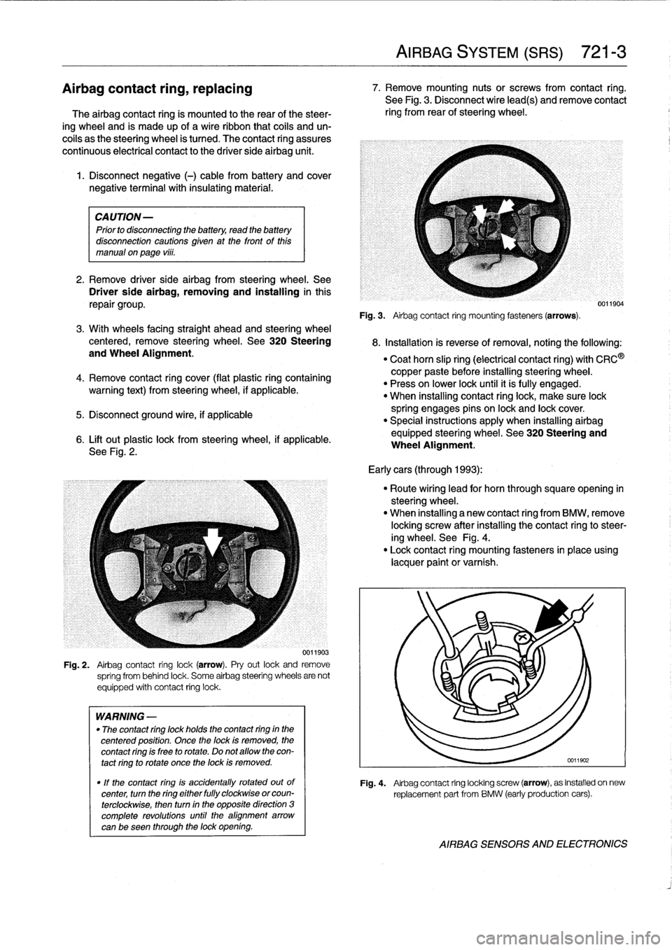
Fig
.
2
.
0011903
Fig
.
2
.
Airbag
contact
ring
lock(arrow)
.
Pry
out
lock
and
remove
spríng
from
behind
lock
.
Some
airbag
steering
wheels
are
not
equipped
with
contact
ring
lock
.
WARNING
-
"
The
contact
ring
lock
holds
the
contact
ring
in
the
centered
position
.
Once
the
lock
is
removed,
the
contact
ring
is
free
to
rotate
.
Do
not
allow
the
con-
tact
ring
to
rotate
once
the
lock
is
removed
.
"
If
the
contact
ring
is
accidentally
rotated
outof
center,
turn
the
ring
either
fully
clockwise
orcoun-
terclockwise,
then
turn
in
the
opposite
direction
3
complete
revolutions
until
the
alignment
arrow
canbe
seen
through
the
lock
opening
.
AIRBAG
SYSTEM
(SRS)
721-
3
Airbagcontact
ring,
replacing
7
.
Remove
mounting
nutsor
screws
from
contact
ring
.
See
Fig
.
3
.
Disconnect
wire
lead(s)
andremove
contact
The
airbag
contact
ring
is
mounted
to
the
rear
of
the
steer-
ring
from
rear
of
steering
wheel
.
ing
wheel
and
is
made
up
of
a
wireribbon
that
cofs
and
un-
coils
as
the
steering
wheel
is
tumed
.
The
contact
ring
assures
continuous
electrical
contact
to
the
driver
side
airbag
unit
.
Fig
.
3
.
Airbag
contact
ring
mounting
fasteners(arrows)
.
8
.
Installation
is
reverse
ofremoval,noting
the
following
:
"
Coat
horn
slip
ring
(electrical
contact
ring)
with
CRC
®
copper
paste
before
installing
steering
wheel
.
"
Press
on
lower
lock
until
it
ís
fully
engaged
.
"
When
installing
contact
ringlock,
make
sure
lock
spring
engages
pins
on
lock
and
lock
cover
.
"
Special
instructions
apply
when
installing
airbag
equipped
steering
wheel
.
See320
Steering
and
Wheel
Alignment
.
Early
cars
(through
1993)
:
"
Route
wiring
lead
for
horn
through
squareopening
in
steering
wheel
.
"
When
installing
a
new
contact
ring
from
BMW,
remove
locking
screw
after
installing
the
contact
ringto
steer-
ing
wheel
.
See
Fig
.
4
.
"
Lock
contact
ring
mounting
fasteners
in
place
using
lacquer
paint
or
varnish
.
0011904
Fig
.
4
.
Airbag
contact
ring
locking
screw
(arrow),
as
installed
on
new
replacement
part
from
BMW
(early
production
cars)
.
AIRBAG
SENSORS
AND
ELECTRONICS
Page 482 of 759
721-
6
AIRBAG
SYSTEM
(SRS)
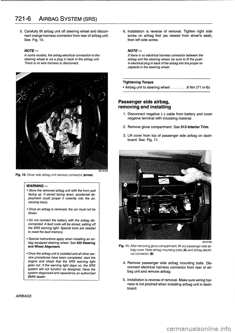
5
.
Carefully
lift
airbag
unit
off
steering
wheel
and
discon-
6
.
Installation
is
reverse
of
removal
.
Tighten
right
side
nect
orange
harness
connector
from
rear
of
airbag
unit
.
screw
on
airbag
first
(as
viewedfrom
driver's
seat),
See
Fig
.
10
.
then
left
side
screw
.
NOTE-
NOTE-
In
some
models,
theairbag
electrical
connection
to
the
If
there
is
no
electrical
harness
connector
between
the
steering
wheel
isvia
aplug
in
back
of
the
airbag
unit
.
airbag
and
the
steering
wheel,
be
sure
to
fit
the
push
There
is
no
wire
harness
to
disconnect
.
in
electrical
plug
in
back
of
the
airbag
finto
the
proper
re-
ceptacle
in
the
steering
wheel
.
Fig
.
10
.
Driver
sideairbag
unit
harness
connector
(arrow)
.
AIRBAGS
WARNING
-
"
Store
the
removed
airbag
unit
with
the
horn
pad
facing
up
.
If
stored
facing
down,
accidental
de-
ployment
couldpropel
it
violently
into
the
air,
causing
injury
.
"
Once
an
airbag
is
removed,
the
car
must
not
be
driven
.
"
Do
not
connect
the
battery
with
the
airbag
dis-
connected
.
A
fault
code
will
be
stored,
setting
off
the
SRS
warning
light
.
Special
tools
are
needed
to
reset
the
fault
memory
.
"
Special
instructions
apply
when
installing
an
air-
bag
equipped
steering
wheel
.
See
320
Steering
and
Wheel
Alignment
.
"
Once
the
airbag
unit
is
installnd
and
all
other
ser-vice
procedureshave
been
completed,
start
the
engíne
and
check
that
the
SRS
warning
light
goes
out
.
If
the
warning
light
stays
on,
the
SRS
system
will
not
function
as
designed
.
Have
the
system
diagnosed
and
repaired
by
an
authorized
BMW
dealer
.
0013184
Tightening
Torque
"
Airbag
unitto
steering
wheel
........
8
Nm
(71
in-lb)
Passenger
side
airbag,
removing
and
installing
1
.
Disconnect
negative
(-)
cable
from
battery
and
cover
negative
terminal
with
insulating
material
.
2
.
Remove
glove
compartment
.
See
513
Interior
Trim
.
3
.
Lift
cover
from
topof
passenger
sideairbag
on
dash-
board
.
See
Fig
.
11
.
0013108
Fig
.
11
.
After
removing
glove
compartment,
lift
out
passenger
side
air-
bag
cover
.
Note
airbag
mounting
bolts
(A)
and
airbag
electri-
cal
connector
(B)
.
4
.
Remove
passenger
sideairbag
mounting
bolts
.
Dis-
connect
electrical
harness
connector
from
rear
of
air-
bag
unit
and
remove
airbag
.
5
.
Installation
is
reverse
of
removal
.
Make
sure
wiring
har-
ness
is
not
pínched
when
installing
airbag
unit
in
dash-board
.
Page 485 of 759
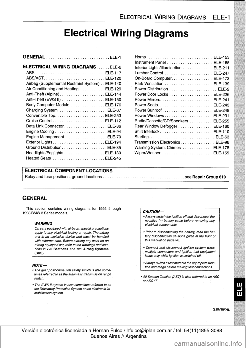
GENERAL
This
section
contains
wiring
diagrams
for
1992
through
1998
BMW
3
Series
models
.
WARNING
-
On
cars
equipped
with
airbags,
special
precautions
apply
to
any
electrical
testing
or
repair
.
The
airbag
unit
is
an
explosive
device
and
must
be
handled
with
exterme
care
.
Before
starting
any
work
onan
airbag
equipped
car,
refer
to
the
warnings
and
cau-
tions
in
720
Seatbelts
and
721
Airbag
Systems
(SRS)
.
NOTE-
The
"
gear
position/neutral
safetyswitch
is
also
some-
timesreferred
to
as
the
automatic
transmission
range
switch
.
"
The
EWS
11
system
is
also
sometimes
referred
to
as
the
Driveaway
Protection
System
or
the
electronic
im-
mobilization
system
.
ELECTRICAL
WIRING
DIAGRAMS
ELE-1
Electrical
Wiring
Diagrams
GENERAL
.
.
.
.
.
.
.
.
.
................
.
.
.
ELE-1
Horns
.....
.
.....
.
.
.
....
.
.
.
.
.
...
.
.
ELE-153
Instrument
Panel
.
.
.
.
.
.
..............
ELE-165
ELECTRICAL
WIRING
DIAGRAMS
...
.
.
.
ELE-2
Interior
Lights/Illumination
.............
ELE-211
ABS
..............
.
.
.
.....
.
.....
ELE-117
Lumbar
Control
.
....................
ELE-247
ABS/AST
.............
.
.
.
...
.
.
.
.....
ELE-120
On-Board
Computer
..................
ELE-173
Airbag
(Supplemental
Restraint
System)
..
ELE-140
Park
Ventilation
.
.
.
...........
.
...
.
..
ELE-139
Air
Conditioning
and
Heating
.
.
.
.
.
.
.....
ELE-129
Power
Distribution
......
.
...
.
.
.
.
.
.
.
...
.
ELE-2
Anti-Theft
(Alpine)
..........
.
.
.
...
.
...
ELE-144
Power
Door
Locks
.
.
......
.
.
.
.
.
.
.
.
.
..
ELE-226
Anti-Theft
(EWS
II)
.
........
.
.
.
...
.
...
ELE-150
Power
Mirrors
...
.
.
.
......
.
.
.
.
.
.
.
.
.
..
ELE-241
Body
Computer
Module
.....
.
.....
.
...
ELE-176
Power
Seats
......
.
......
.
.
.
...
.
.
.
..
ELE-243
Charging
System
.
.
................
.
.
.
ELE-67
Power
Sunroof
.
.
.
.
.
.
.
...............
ELE-248
Convertible
Top
.
.
.
.
................
.
.
ELE-253
Power
Windows
.
.
.
.
.
.
.....
.
.........
ELE-231
Cruise
Control
..
.
.
.
...........
.
....
.
.
ELE-112
Radio/Cassette/CD/Speakers
..........
ELE-255
Data
Link
Connector
................
.
.
.
ELE-86
Rear
Window
Defogger
...............
ELE-160
Engine
Cooling
.......
.
.......
.
....
.
.
.
ELE-94
Shift
Interlock
.
.
.
.
.
.
.
.
...............
ELE-110
Engine
Management
...
.
.......
.
....
.
.
.
ELE-70
Starting
....
.
.
.
.
.
...
.
................
ELE-63
Exterior
Lights
........
.
.
.
.
.
.
.
.
.
......
ELE-194
Transmission
Electronics
.
..............
ELE-96
Ground
Distribution
....
.
.
.
.
.
.
.
.
.
.......
ELE-35
Warning
System
:
Chimes
.............
ELE-178
Headlights/Foglights
...
.
.
.
.
.
.
.
.
.
......
ELE-180
Wiper/Washer
.
.....
.
...............
ELE-155
Heated
Seats
........
.
.
.
.
.
.
.
.
.
......
ELE-245
ELECTRICAL
COMPONENT
LOCATIONS
Relayand
fuse
positions,
ground
locations
...........
.
.
.
.
.
.
.
.
.
................
seeRepair
Group
610
CAUTION-
Always
switchthe
ignition
off
and
disconnect
the
negative
(-)
battery
cablebefore
removing
any
electrical
components
.
"
Prior
to
disconnecting
the
battery,
read
the
bat-tery
disconnection
cautions
given
at
the
front
of
this
manual
on
page
viii
.
"
Connect
and
disconnect
ignition
system
wires,
multiple
connectors
and
ignition
test
equipment
leads
only
while
ignition
is
switched
off
.
-Always
switch
a
test
meter
to
the
appropiate
func-
tion
and
range
before
making
test
connections
.
"
All-Season
Traction
(AST)
is
also
referred
to
as
ASC
or
ASC+T
.
GENERAL
Page 486 of 759
ELE--2
ELECTRICAL
WIRING
DIAGRAMS
FUSE
LINK
64766
I-i
I
-
i
a
1
I
_
ZJ
I
I
I
I
I
I.
4
2
GRN/VIO
I_I
!
___I
I_I
1
D>
6
END
INECONTROL
ENGINECONTROL
TRANSMISSION
CONTROL
DATALINK
MODULE
MODULE
RELAY
MODULE
(EGS)
CONNECTOR
I
I
I
I
5
(F18
--_______________________________________________
O19~
N
RIBUON
BOX
I
FUSE
II
15A
o~___________________________________________________Q~____-aft
TO
FUSE
F5
C
RED
(DIAGRAM
6
OF
7)
FUELPUMP
I
(DIAGRAM60F7)
C'
RED
\
L------r>
(DIAGRAM60F7)
I
LOW
F
I
FRONT
HIGH
BEAM
FOGJ
BEAM
I
I
LIGHT
I
I
LIGHT
I
j
/
I
LIGHT
RELAY
I
RELAY
li
SJ
RELAY
1992
1993W/TRUNK
MOUNTEDBATTERV
1993W/ENGINE
COMPARTMENTMOUNTEDBATTERV
1993W/TRUNK
1993W/ENGINE
1992
1992
WI
ENGINE
W/TRUNK
BATTERY
MOUNTEDBATTERV
¢)
MOUNTED
BATTERY
MOUN
O
TEDBATT
I
ERV
¢I¢I
MOUNTEDBATTERV
TOFUSEF40
<
,.k
RED
(DIAGRAM
6
OF
7)
I
I
(DIAGRAM
3
OF
7)
TO
FUSEF3
E
RED
(DIAGRAMfiOF7)
"
.
1k
I
(DIAGRAM
6OF7)
>I
mJ~CANADA
RED
BNUMPSTART
JUNCTION
POINT
REO
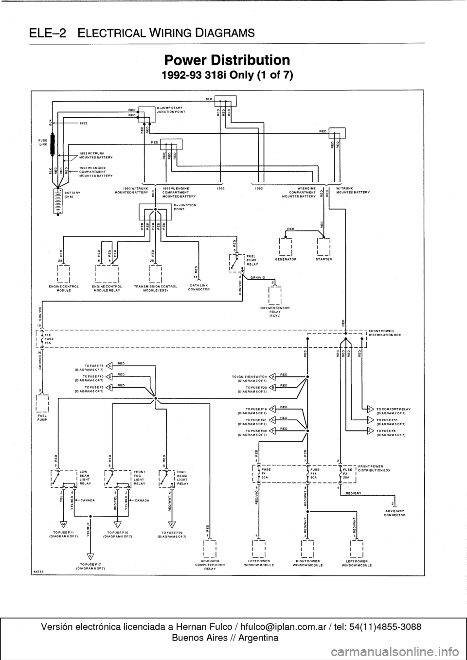
Power
Distribution
1992-93
318i
Only
(1
of
7)
-UNCTION
POINT
TOFUSEF15
TO
FUSE
F29
(DIAGRAM60F7)
(OIAGRAM6OF7)
I
~1
.
FUEL
_I
I
_I
~
(PUMP
GENERATOR
STARTER
I
,(
I
RELAY
TO
IGNITION
SWITCH
QA
TOFUSE
F20
TOFUSEF19
FRED
(DIAGRAM6OF7)
`
I
III
-
(DIAGRAM70F7)
OXVGENSENSOR
RELAY
(4CVL)
RED
RED
RED
ON-BOARD
LEFTPOWERRIGHTPOWERLEFTPOWER
TOFUSEF17
COMPUTERHORN
WINDOWMODULE
WINDOWMODULE
WINDOW
MODULE
(DIAGRAM
60F
7)
RELAY
TO
COMFORTRELAV
Page 487 of 759
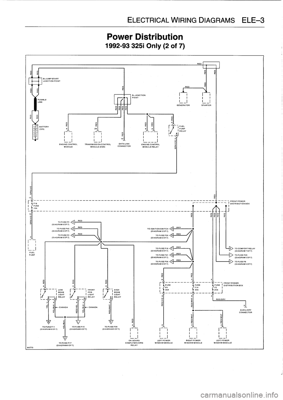
ELE
Power
L
1992-9332
RED
E01
IIIII
FUSIBLE
LINK
I
GENERATOR
STARTER
BATTERY
¢
(FUEL
-
(325)
S
26
66
PUMP
I
I
RELAY
2
G
ENGINE
CONTROL
TRANSMISSION
CONTROL
DATA
LINK
ENGINECONTROL
iMODULE
MODULE
(EGG)
CONNECTOR
MODULE
RELAY
15
--
---
-
-
----
--
FRONT
POWER
FUSE
r
-
i
DISTRIBUTIONBO
;
I
16A
R
ITIT
TO
FUSE
FS
ED
C
(DIAL
RAM
6
OF
7)
TO
FUSE
F40
D
RED
TO
IGNITION
SWITCH
A
RED
(DIAGRAM
6
OF
7)
(DIAGRAM
3
OF
7)
TO
FUSE
F3
E
RED
TO
FUSE
F20
B
RED
2
(DIAGRAM6OF7)
(DIAGRAM
6OF7)
I
I
I
I
-
I
TOFUSEF19
:
:!!RED---
RED
S
TOCOMFORTI
(DIAGRAM
6
OF
7)
(DIAGRAM
70
FUEL
PUMP
TO
FUSE
F41
V\
TOFUGEF35
(DIAGRAM
B
OF
7)
\
(DIAGRAM
50
TOFUSEFSB
H
RED
"
J
TOFUSEF
.
(DIAGRAM
6
0F
7)
(DIAGRAM
50
8
7
3
FUGE
FUSE
FUSE
I
FRONT
POWER
B
6
6
DISTRIBUTION
BOX
F4
F14
F2
I
LOW
FRONT
HIGH
I
30A
30A
~
.1
.
25A
BEAM
F
I
FOG
F
(
BEAM
i
_________
_____
J
I
I
LIGHT
I
I
LIGHT
I
.
I
LIGHT
l
RELAY
I
-
RELAY
I
-
WJ
_RELAY
6
B
4
-
-
-
O
RED/GRY
3
21
2
B
62
2
~
-
CANADA
j
m
-CANADA
3
"
AUXILIAI
CONNECT
"
3
3
M
L
K
4(D
IAGAGR
AM60
F7)
(DIAGRAM
IAGRAM
B
OFOF
7)
(DIAGRAM
6
0
6
3
3G
FO
F
~
7)
I
I
I
I
I
II
I
I
I
I
I
I
I
!
_I
!
_I
!
_I
!
_
17
I
ON-BOARD
LEFTPOWER
RIGHTPOWER
LEFT
POWERTOFUSEFI7
COMPUTERHORN
WINDOW
MODULE
WINDOWMODULE
WI
NDOWMODULE
(DIAGRAMS
OF7)
RELAY
64770