weight BMW 328i 1995 E36 User Guide
[x] Cancel search | Manufacturer: BMW, Model Year: 1995, Model line: 328i, Model: BMW 328i 1995 E36Pages: 759
Page 243 of 759

Symptom
1
Probable
cause
4
.
Vibration,
audible
a
.
Front
centering
guide
worn,
or
a
.
Check
front
centering
guide
and
replace
if
necessary
.
Check
rumble
over35
mph
driveshaft
mounting
flanges
out
of
runout
of
driveshaft
mounting
flanges
.
(60
km/h)
.
round
or
damaged
.
b
.
Mounting
flange
bolts
loose
or
holes
b
.
Remove
driveshaft
and
check
transmissionoutput
flange
and
worn
.
final
drive
input
flange
.
Replace
if
necessary
.
c
.
Driveshaft
unbalanced
.
c
.
Check
driveshaft
for
loose
or
missing
balance
weights
.
Have
driveshaft
rebalanced
or
replace
if
necessary
.
DRIVESHAFT
SERVICE
Driveshaft,
aligning
d
.
Universal
joints
worn
or
seized
.
d
.
Check
universal
joint
play
and
movement
.
Replace
driveshaft
if
necessary
.
e
.
Sliding
coupling
seized
.
e
.
Remove
driveshaft
and
check
movement
of
sliding
coupling
.
1
Clean
coupling
splines
or
replace
parts
asnecessary
.
f
.
Incorrect
preload
of
center
bearing
.
f
.
Check
preload
of
center
bearing
.
Readjust
if
necessary
.
g
.
Center
bearing
faulty
.
g
.
Replace
center
bearing
.
h
.
Final
drive
rubber
mount
faulty
h
.
Inspect
final
drive
rubber
mount
and
replace
if
necessary
.i.
Driveshaft
misaligned
.
i.
Check
driveshaft
alignment
.
Repair
kits
for
the
universal
joints
are
not
available,
and
it
is
not
common
practice
to
repair
the
universal
joints
on
BMW
driveshafts
.
Worn
or
damaged
universal
joints
usually
require
replacement
of
that
section
of
the
driveshaft
.
The
driveshaft
is
balanced
to
cose
tolerances
.
Whenever
it
is
to
be
removed
or
disassembied,
the
mounting
flanges
and
driveshaft
sections
should
bemarked
with
paint
or
a
punch
before
proceeding
with
work
.
This
will
ensure
that
the
drive-
shaft
can
be
reassembled
or
installed
in
exactlythe
same
ori-
entation
.
Universal
joint
play
"
Maximum
allowable
...........
0.15
mm
(0.006
in
.)
The
alignment
of
the
driveshaft
does
not
normally
need
to
be
checked
unless
the
engine/transmission
orthe
final
drive
havebeen
removed
and
installed
.
If,
however,
all
other
parts
of
the
driveshaft
havebeen
inspected
and
found
to
be
okay,
butthere
is
still
noise
or
vibration,
driveshaft
alignment
should
be
checked
.
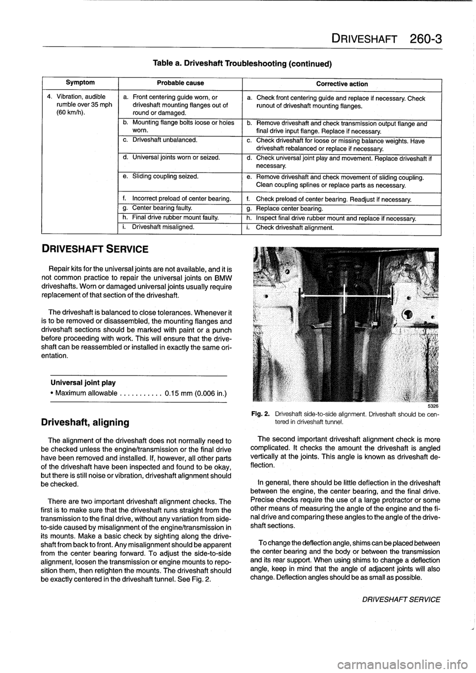
There
aretwo
important
driveshaft
alignment
checks
.
The
first
is
to
make
sure
that
the
driveshaft
runs
straight
from
the
transmission
to
the
final
drive
;
without
any
variation
from
side-
to-side
caused
by
misalignment
ofthe
engine/transmission
in
its
mounts
.
Make
a
basic
check
by
sighting
along
the
drive-
shaft
from
back
lo
front
.
Any
misalignmentshould
be
apparent
from
the
center
bearingforward
.
To
adjustthe
side-to-side
alignment,
loosen
the
transmission
or
engine
mounts
to
repo-
sition
them,
then
retighten
the
mounts
:
The
driveshaft
should
be
exactly
centered
in
the
driveshaft
tunnel
.
See
Fig
.
2
.
Table
a
.
Driveshaft
Troubleshooting
(continued)
DRIVESHAFT
260-3
Corrective
action
b
:izó
Fig
.
2
.
Driveshaft
side-to-side
alignment
.
Driveshaft
should
be
cen-
tered
in
driveshaft
tunnel
.
The
second
important
driveshaft
alignment
check
is
more
complicated
.
It
checks
the
amount
the
driveshaft
is
angled
vertically
at
the
joints
.
This
angle
is
known
as
driveshaft
de-
flection
.
In
general,
there
should
be
little
deflection
in
the
driveshaft
between
the
engine,
thecenter
bearing,
and
the
final
drive
.
Precise
checks
require
theuse
of
a
large
protractor
or
some
other
means
of
measuring
the
angle
of
the
engine
and
the
fi-
nal
drive
and
comparing
these
angles
to
the
angle
of
the
drive-
shaft
sections
.
To
change
the
deflection
angle,
shims
can
be
placed
between
the
center
bearing
and
the
body
or
between
the
transmission
and
íts
rear
support
.
When
using
shims
to
change
a
deflection
angle,
keep
in
mind
that
the
angle
of
adjacent
joints
will
also
change
.
Deflection
anglesshould
beas
small
as
possible
.
DRIVESHAFTSERVICE
Page 265 of 759

STABILIZER
BAR
Stabilizer
bar,
removing
and
installing
Stabilizer
bar
link
arrangements
differ
slightly
among
mod-
els
.
In
most
models
the
links
attach
lo
the
control
arms
near
the
outboard
end
.
OnM3
models
the
links
attach
lo
the
strut
assemblies
.
1
.
Raise
car
and
remove
both
front
wheels
.
WARNING
-
Make
sure
that
the
car
is
firmly
supported
on
jack
stands
desígned
for
the
purpose
.
Place
the
jack
stands
beneath
a
structural
chassís
point
.
Do
not
place
jack
stands
under
suspension
parts
.
uul
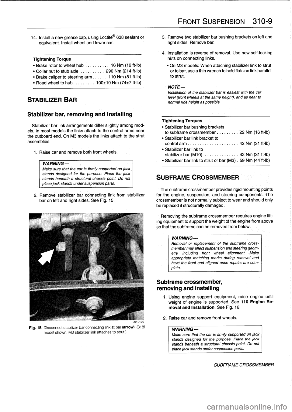
Fig
.
15
.
Disconnect
stabilizer
bar
connecting
link
at
bar
(arrow)
.
(3181
model
shown
.
M3
stabilizer
link
attaches
lo
strut
.)
FRONT
SUSPENSION
310-
9
14
.
Insta¡¡
a
new
grease
cap,
using
Loctite
©
638
sealant
or
3
.
Remove
two
stabilizer
bar
bushing
brackets
on
left
and
equivalent
.
Insta¡¡
wheel
and
lower
car
.
right
sides
.
Remove
bar
.
4
.
Installation
is
reverse
of
removal
.
Use
new
seif-lockíng
Tightening
Torque
núts
on
connecting
links
.
"
Brake
rotor
lo
wheel
hub
..........
16
Nm
(12
ft-Ib)
"
On
M3
models
:
When
attaching
stabilizer
link
lostrut
"
Collar
nut
lo
stubaxle
.
.........
290
Nm
(214
ft-Ib)
orlobar,
usea
thin
wrench
lo
hold
flats
on
link
parallel
"
Brake
caliper
losteering
arm
......
110
Nm
(81
ft-Ib)
lo
strut
.
"
Road
wheel
lo
hub
...
...
.
.
.
100±10
Nm
(74t7
ft-Ib)
NOTE-
Installation
of
the
stabilizer
bar
is
easiest
with
thecar
leve¡
(front
wheels
at
the
same
height),
and
as
near
to
normal
ride
height
as
possible
.
Tightening
Torques
"
Stabilizer
bar
bushing
brackets
lo
subframe
crossmember
...
..
.
..
.
22
Nm
(16
ft-Ib)
"
Stabilizer
bar
link
bracket
lo
control
arm
................
.
.
.
.
.
42
Nm
(31
ft-1b)
"
Stabilizer
bar
link
lo
stabilizer
bar
(M10)
.............
.
42
Nm
(31
ft-Ib)
"
Stabilizer
bar
link
lostrut
or
bar
(M3)
.
59
Nm
(44
ft-Ib)
SUBFRAME
CROSSMEMBER
The
subframe
crossmember
provides
rigid
mounting'poínts
2
.
Remove
stabilizer
bar
connecting
link
from
stabilizer
for
the
engine,
suspension,
and
steering
components
.
The
baron
left
and
right
sides
.
See
Fig
.
15
.
crossmember
is
not
normally
subject
lo
wear
and
should
ohly
be
replaced
if
structurally
damaged
.
Removing
the
subframe
crossmember
requires
engine
lift-
ing
equipment
lo
support
theweight
of
tfhe
engine
from
above
so
that
the
subframe
can
be
removed
from
below
.
WARNING-
Removal
or
replacement
of
the
subframe
cross-
member
may
affect
suspension
and
steering
geom-
etry,
including
front
wheel
afignment
.
Make
appropriate
matching
marks
during
removal
and
have
the
front
end
aligned
once
repairs
are
com-
plete
.
Subframe
crossmember,
removing
and
installing
1
.
Using
enginesupport
equipment,
raise
engine
until
weight
of
engine
is
supported
.
See
110EngineRe-
moval
and
Installation
.
See
Fig
.
16
.
2
.
Raise
car
andremove
front
wheels
.
WARNING-
Make
sure
that
the
car
is
firmly
supportedon
jack
stands
desígned
for
the
purpose
.
Place
the
jack
stands
beneatha
structural
chassís
point
Do
not
place
jack
standsundersuspension
parts
.
SUBFRAME
CROSSMEMBER