wheel bolts BMW 328i 1995 E36 Repair Manual
[x] Cancel search | Manufacturer: BMW, Model Year: 1995, Model line: 328i, Model: BMW 328i 1995 E36Pages: 759
Page 301 of 759
7
.
Turn
on
ignition
.
Check
that
light
comes
on
as
soonas
4
.
Remove
parkíng
brake
shoes
as
described
above
.
lever
is
pulled
up
.
5
.
Disconnect
cable
from
parking
brake
actuator
and
then
8
.
Install
parking
brake
lever
boot
.
Install
road
wheel
lug
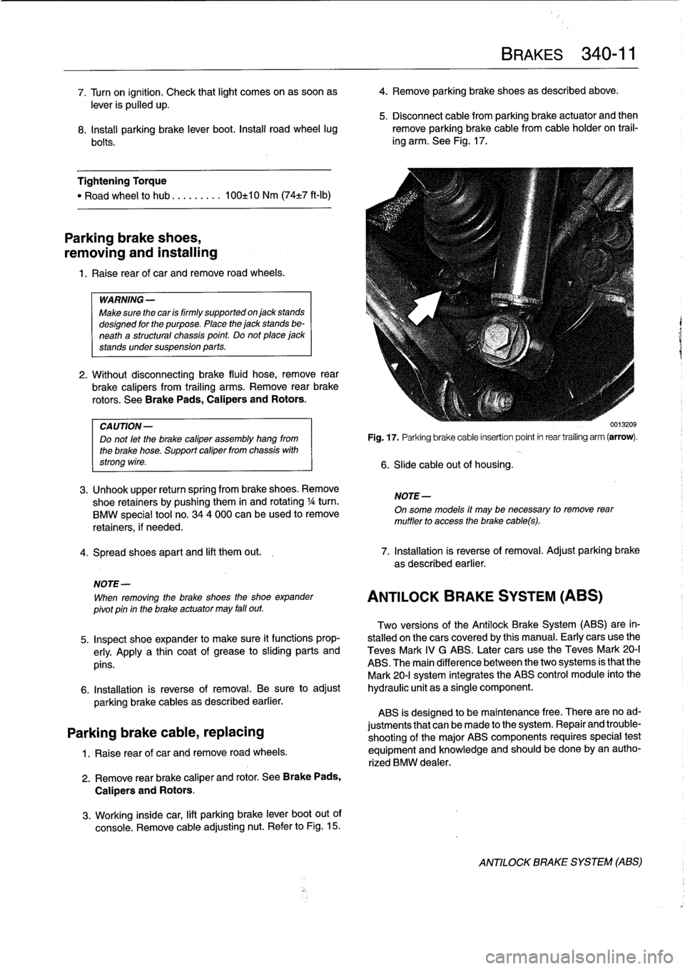
remove
parking
brakecable
from
cable
holder
on
trail-
bolts
.
ing
arm
.
See
Fig
.
17
.
Tightening
Torque
"
Road
wheel
to
hub
.
..
......
100±10
Nm
(74±7
ft-Ib)
Parking
brake
shoes,
removing
and
installing
1.
Raise
rear
of
car
andremove
road
wheels
.
WARNING
-
Make
sure
the
car
is
firmly
supportedon
jack
stands
designed
for
the
purpose
.
Place
the
jack
stands
be-
neath
a
structural
chassis
point
.
Do
not
place
jack
stands
undersuspension
parts
.
2
.
Without
disconnecting
brake
fluid
hose,
remove
rear
brake
calipers
from
trailing
arms
.
Remove
rear
brake
rotors
.
See
Brake
Pads,
Calipers
and
Rotors
.
CA
UTION-
Do
not
let
the
brake
caliper
assembly
hang
from
the
brake
hose
.
Support
caliper
from
chassis
with
strong
wire
.
3
.
Unhook
upper
return
spring
from
brake
shoes
.
Remove
shoe
retainers
bypushing
them
in
and
rotating
1
/4turn
.
BMW
special
tool
no
.
344
000
can
beused
to
remove
retainers,
if
needed
.
4
.
Spread
shoes
apart
and
lift
them
out
.
7
.
Installation
is
reverse
of
removal
.
Adjust
parking
brake
as
described
earlier
.
NOTE-
When
removing
the
brake
shoes
the
shoe
expander
pivot
pin
in
the
brake
actuator
may
fall
out
.
Two
versions
of
the
Antilock
Brake
System
(ABS)
are
in-
5
.
Inspect
shoe
expander
to
make
sure
it
functions
prop-
stalled
onthe
cars
coveredby
this
manual
.
Early
cars
use
the
erly
.
Apply
a
thin
coat
of
grease
tosliding
parts
and
Teves
Mark
IV
G
ABS
.
Later
cars
use
the
Teves
Mark
20-I
pins
.
ABS
.
The
main
difference
between
the
two
systems
is
that
the
Mark
20-I
system
integrates
the
ABS
control
module
into
the
6
.
Installation
is
reverse
of
removal
.
Be
sure
to
adjust
hydraulic
unit
as
a
single
component
.
parking
brake
cables
as
described
earlier
.
ABS
is
designed
to
be
maintenance
free
.
There
are
noad
Parking
brake
cable,
replacing
justments
that
canbe
made
to
the
system
.
Repair
and
trouble-
shooting
of
the
major
ABS
components
requires
special
test
1
.
Raise
rear
of
car
and
remove
road
wheels
.
equipment
and
knowiedge
and
should
be
done
by
an
autho-
rized
BMW
dealer
.
2
.
Remove
rear
brake
caliper
and
rotor
.
See
Brake
Pads,
Calipers
and
Rotors
.
3
.
Working
inside
car,
lift
parking
brake
lever
boot
out
of
console
.
Remove
cable
adjusting
nut
.
Refer
to
Fig
.
15
.
Fig
.
17
.
Parking
brake
cable
insertion
point
in
rear
trailing
arm
(arrow)
.
6
.
Slide
cable
out
of
housing
.
NOTE
-
BRAKES
340-
1
1
On
some
models
it
may
be
necessary
to
remove
rear
muffler
to
access
the
brake
cabes)
.
ANTILOCK
BRAKE
SYSTEM
(ABS)
0013209
ANTILOCK
BRAKE
SYSTEM
(ABS)
Page 309 of 759
GENERAL
This
repair
group
covers
replacement
of
the
front
fenders
and
removal
and
installation
of
the
engine
hood
.
NOTE-
The
body
is
painted
at
the
factoryafter
assembly
.
Re-
alignment
of
body
panels
may
expose
unpainted
metal
.
Paint
all
exposed
metal
once
the
work
fs
complete
.
FRONT
FENDERS
Front
fender,
removing
and
installing
1
.
Raise
hood
.
Raise
and
safely
support
front
of
vehicle
.
WARNING
-
"
When
raising
thecar
using
a
floor
jack
or
a
hy-
draulic
lift,
carefully
position
the
jack
pad
to
pre-
vent
damaging
thecar
body
.
A
suitable
liner
(wood,
rubber,
etc
.)
should
be
placed
between
the
jack
and
the
car
to
prevent
body
damage
.
"
Watch
the
jack
closely
.
Make
sure
it
stays
stable
and
does
not
shift
or
tilt
.
As
the
car
is
raised,
the
car
may
roll
slightly
and
the
jack
may
shift
.
2
.
Remove
front
wheel
.
Remove
inner
plastic
liner
from
wheel
well
.
3
.
Remove
front
bumper
.
See510
Exterior
Trim,
Bumpers
.
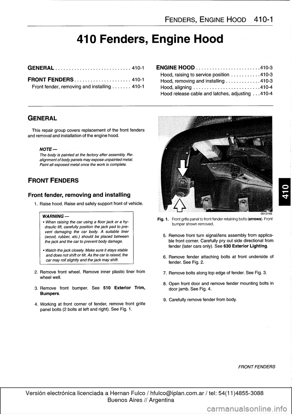
4
.
Working
atfront
corner
of
fender,
remove
front
grille
panel
bolts
(2
bolts
at
left
and
right)
.
See
Fig
.
1
.
FENDERS,
ENGINE
HOOD
410-1
410
Fenders,
Engine
Hood
GENERAL
...............
.
.
.
.
.
.
.
.
.
.
.
..
410-1
ENGINE
HOOD
.
.
.
.
.
.
.
.
.
.
.
.
.
.
.
.
.
.
.
...
.
.410-3
Hood,
raising
to
service
position
.
.
.
.
.
.
.
.
...
410-3
FRONTFENDERS
........
.
.
.
.
.
.
.
.
.
.
.
.
.410-1
Hood,
removin
and
installin
410-3
Front
Pender,
removing
and
installing
.
.
.
....
410-1
Hood,
aligning
...
.
.
.
.
.
.
.
.....
.
.
.
.
.
.
.
...
410-4
Hood
release
cable
and
latches,
adjusting
...
410-4
001
.145
Fig
.
1
.
Front
grille
panel
to
front
fender
retaining
bolts
(arrows)
.
Front
bumpershown
removed
.
5
.
Remove
front
turn
signalliens
assembly
from
applica-
ble
front
corner
.
Carefully
pryout
side
directional
from
fender
(later
cars
only)
.
See
630
Exterior
Lighting
.
6
.
Remove
fender
attaching
bolts
atfront
underside
of
fender
.
See
Fig
.
2
.
7
.
Remove
bolts
along
top
edge
of
fender
:
See
Fig
.
3
.
8
.
Open
front
door
and
remove
fender
mounting
bolts
in
door
jamb
.
See
Fig
.
4
.
9
.
Carefully
remove
fender
from
body
.
FRONTFENDERS
Page 326 of 759
510-4
EXTERIOR
TRIM,
BUMPERS
Fig
.
8
.
Bumper
cover
retaining
screws
(arrows)
in
left
wheel
weil
.
7
.
Disconnect
harnessconnectors
at
outside
temperature
0013052
sensor
at
rear
of
left
side
of
bumperand
temperatura
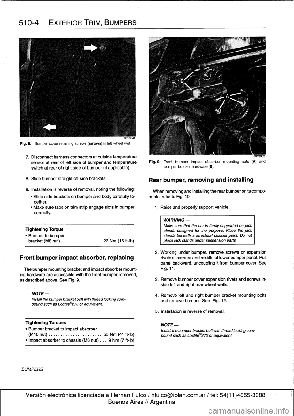
Fig
.
9
.
Front
bumper
impact
absorber
mounting
nuts
(A)
and
switch
at
rear
of
right
side
of
bumper
(if
applicable)
.
bumper
bracket
hardware
(B)
.
8
.
Slide
bumper
straight
off
sida
brackets
.
9
.
Installation
is
reverse
of
removal,
notingthe
following
:
When
removing
and
installing
therear
bumper
or
its
compo-
"
Slide
side
brackets
on
bumper
and
body
carefully
to-
nents,
referto
Fig
.
10
.
gether
.
"
Make
sure
tabs
on
trim
strip
engage
slots
in
bumper
1
.
Raise
and
properly
support
vehicle
.
correctly
.
Tightening
Torque
"
Bumper
to
bumper
bracket
(M8
nut)
............
...
.
.
22
Nm
(16
ft-Ib)
2
.
Working
under
bumper,
remove
screws
or
expansion
Front
bumper
impact
absorber,replacing
rivetsat
corners
and
middle
of
lower
bumper
panel
.
Pull
panel
backward,
uncoupling
it
from
bumper
cover
.
See
Thebumper
mounting
bracket
and
impact
absorber
mount-
Fig
.
11
.
ing
hardware
are
accessible
with
the
Font
bumper
removed,
as
described
above
.
See
Fig
.
9
.
3
.
Remove
bumper
cover
expansion
rivets
and
screws
in-
side
left
and
right
rear
wheel
wells
.
NOTE
-
Install
the
bumper
bracket
boltwith
thread
locking
com-
pound
suchas
Loctite
8
270
or
equivalent
.
Tightening
Torques
"
Bumper
bracket
to
impact
absorber
(M10
nut)
.
..
.
...
.............:.
55
Nm
(41
ft-Ib)
"
Impact
absorber
to
chassis
(M6
nut)
...
9
Nm
(7
ft-Ib)
BUMPERS
Rear
bumper,
removing
and
installing
WARNING
-
Make
sure
that
the
car
is
firmly
supported
on
jack
stands
designad
for
the
purpose
.
Place
the
jack
stands
beneath
a
structural
chassis
point
.
Do
not
place
jack
stands
under
suspension
parts
.
4
.
Remove
left
and
right
bumper
bracket
mounting
bolts
and
remove
bumper
.
See
Fig
.
12
.
5
.
Installation
is
reverse
of
removal
.
NOTE-
Install
the
bumper
bracket
bolt
with
thread
locking
com-
pound
suchas
Loctite®270
or
equivalent
.
Page 347 of 759
Dashboard,
removing
and
installing
1
.
Disconnect
negative
(-)
cable
from
battery
and
cover
terminal
with
insulating
material
.
CAUTION-
Prior
to
disconnectiog
the
battery,
read
the
battery
disconnection
cautionsgiven
at
the
front
of
this
manual
onpage
vi¡¡
.
2
.
Remove
center
console
as
described
earlier
.
3
.
Remove
glove
compartment
as
described
earlier
.
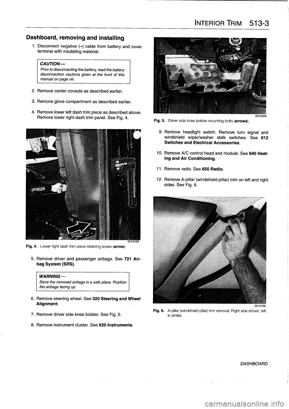
4
.
Remove
lower
left
dash
trim
piece
as
described
above
.
Remove
lower
right
dash
trim
panel
.
See
Fig
.
4
.
Fig
.
4
.
Lower
right
dash
trim
piece
retaining
screw
(arrow)
.
WARNING
-
Store
the
removed
airbags
in
a
safe
place
.
Position
the
airbags
facing
up
.
8
.
Remove
instrument
cluster
.
See
620
Instruments
.
5
.
Remove
driver
and
passenger
airbags
.
See
721
Air-
bag
System
(SRS)
.
6
.
Remove
steering
wheel
.
See
320
Steering
and
Wheel
Alignment
.
INTERIOR
TRIM
513-
3
Fig
.
5
.
Driver
side
knee
bolster
mounting
bolts
(arrows)
.
9
.
Remove
headlight
switch
.
Remove
turn
signal
and
windshield
wiper/washer
stalk
switches
.
See612
Switches
and
Electrical
Accessories
.
10
.
Remove
A/C
control
head
and
module
.
See
640
Heat-ing
and
Air
Conditioning
.
11
.
Remove
radio
.
See650
Radio
.
12
.
Remove
A-pillar
(windshield
pillar)
trim
on
left
and
right
sides
.
See
Fig
.
6
.
UU13156
Fig
.
6
.
A-pillar
(windshield
pillar)
trim
removal
.
Right
side
shown,
left
7
.
Remove
driver
side
knee
bolster
.
See
Fig
.
5
.
is
similar
.
DASHBOARD
Page 482 of 759
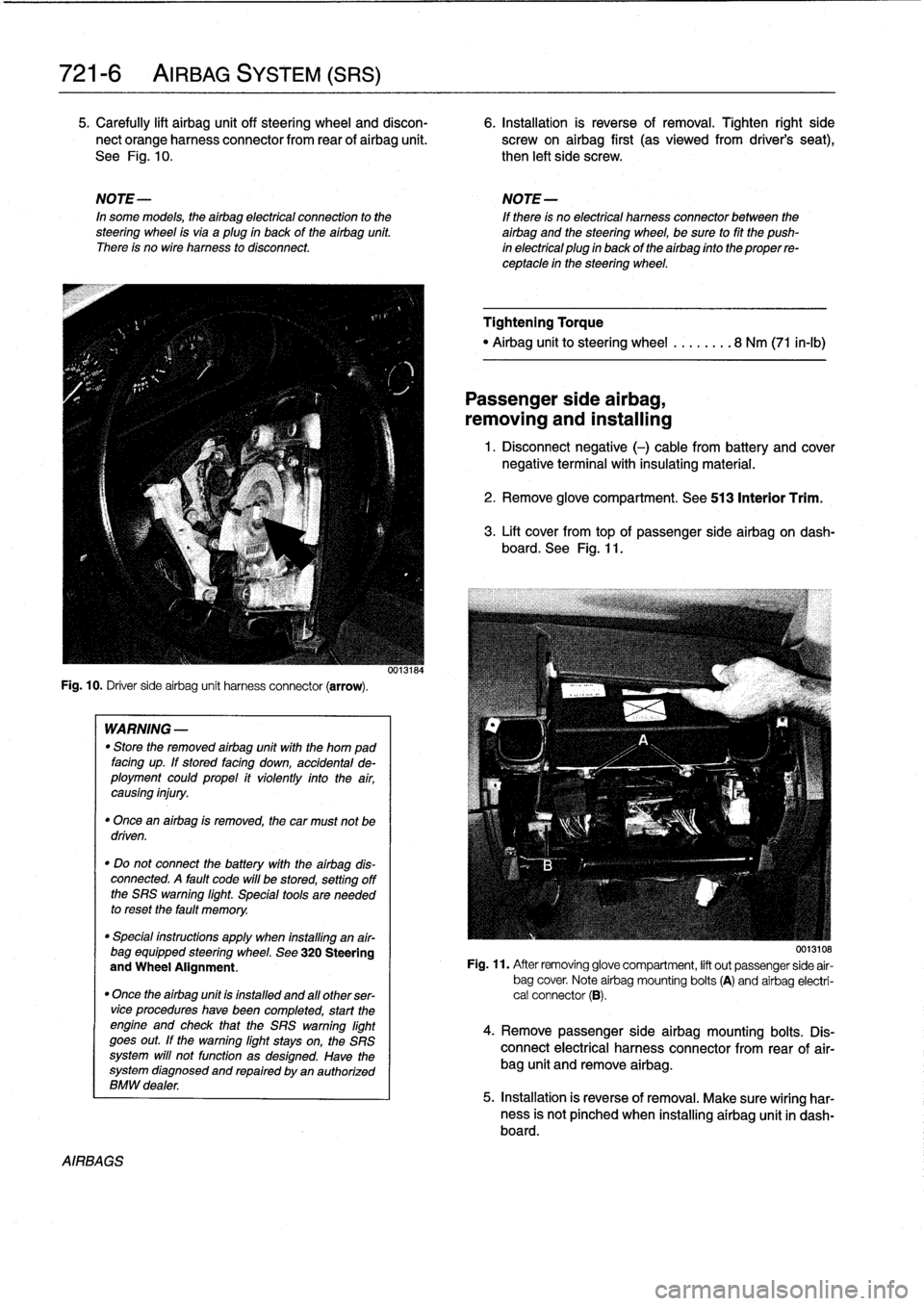
721-
6
AIRBAG
SYSTEM
(SRS)
5
.
Carefully
lift
airbag
unit
off
steering
wheel
and
discon-
6
.
Installation
is
reverse
of
removal
.
Tighten
right
side
nect
orange
harness
connector
from
rear
of
airbag
unit
.
screw
on
airbag
first
(as
viewedfrom
driver's
seat),
See
Fig
.
10
.
then
left
side
screw
.
NOTE-
NOTE-
In
some
models,
theairbag
electrical
connection
to
the
If
there
is
no
electrical
harness
connector
between
the
steering
wheel
isvia
aplug
in
back
of
the
airbag
unit
.
airbag
and
the
steering
wheel,
be
sure
to
fit
the
push
There
is
no
wire
harness
to
disconnect
.
in
electrical
plug
in
back
of
the
airbag
finto
the
proper
re-
ceptacle
in
the
steering
wheel
.
Fig
.
10
.
Driver
sideairbag
unit
harness
connector
(arrow)
.
AIRBAGS
WARNING
-
"
Store
the
removed
airbag
unit
with
the
horn
pad
facing
up
.
If
stored
facing
down,
accidental
de-
ployment
couldpropel
it
violently
into
the
air,
causing
injury
.
"
Once
an
airbag
is
removed,
the
car
must
not
be
driven
.
"
Do
not
connect
the
battery
with
the
airbag
dis-
connected
.
A
fault
code
will
be
stored,
setting
off
the
SRS
warning
light
.
Special
tools
are
needed
to
reset
the
fault
memory
.
"
Special
instructions
apply
when
installing
an
air-
bag
equipped
steering
wheel
.
See
320
Steering
and
Wheel
Alignment
.
"
Once
the
airbag
unit
is
installnd
and
all
other
ser-vice
procedureshave
been
completed,
start
the
engíne
and
check
that
the
SRS
warning
light
goes
out
.
If
the
warning
light
stays
on,
the
SRS
system
will
not
function
as
designed
.
Have
the
system
diagnosed
and
repaired
by
an
authorized
BMW
dealer
.
0013184
Tightening
Torque
"
Airbag
unitto
steering
wheel
........
8
Nm
(71
in-lb)
Passenger
side
airbag,
removing
and
installing
1
.
Disconnect
negative
(-)
cable
from
battery
and
cover
negative
terminal
with
insulating
material
.
2
.
Remove
glove
compartment
.
See
513
Interior
Trim
.
3
.
Lift
cover
from
topof
passenger
sideairbag
on
dash-
board
.
See
Fig
.
11
.
0013108
Fig
.
11
.
After
removing
glove
compartment,
lift
out
passenger
side
air-
bag
cover
.
Note
airbag
mounting
bolts
(A)
and
airbag
electri-
cal
connector
(B)
.
4
.
Remove
passenger
sideairbag
mounting
bolts
.
Dis-
connect
electrical
harness
connector
from
rear
of
air-
bag
unit
and
remove
airbag
.
5
.
Installation
is
reverse
of
removal
.
Make
sure
wiring
har-
ness
is
not
pínched
when
installing
airbag
unit
in
dash-board
.