ECU BMW 328I 2013 Owners Manual
[x] Cancel search | Manufacturer: BMW, Model Year: 2013, Model line: 328I, Model: BMW 328I 2013Pages: 242, PDF Size: 5.38 MB
Page 23 of 242
Voice activation systemVehicle equipment
All standard, country-specific and optional
equipment that is offered in the model series is
described in this chapter. Therefore, equipment
is also described that is not available in a vehicle,
e. g., because of the selected optional equip‐
ment or country variant. This also applies for
safety-related functions and systems.
The concept▷Most functions that are displayed on the
Control Display can be operated by spoken
commands via the voice activation system.
The system prompts you to make your en‐
tries.▷Functions that can only be used when the
vehicle is stationary cannot be operated us‐
ing the voice activation system.▷The system uses a special microphone on
the driver's side.▷›...‹ Verbal instructions in the Owner's
Manual to use with the voice activation sys‐
tem.
Requirements
Via the Control Display, set a language that is
also supported by the voice activation system
so that the spoken commands can be identified.
Set the language, refer to page 85.
Using voice activation
Activating the voice activation system
1. Press the button on the steering
wheel.2.Wait for the signal.3.Say the command.
The command is displayed in the instrument
cluster.
This symbol in the instrument cluster indi‐
cates that the voice activation system is active.
If no other commands are available, operate the
function in this case via iDrive.
Terminating the voice activation
system
Briefly press the button on the steering
wheel or ›Cancel‹.
Possible commands
Most menu items on the Control Display can be
voiced as commands.
The available commands depend on which
menu is currently displayed on the Control Dis‐
play.
Short commands exist for many functions.
Some list entries, e.g., Phone book entries, can
also be selected via the voice activation system.
Speak these list entries exactly as they are dis‐
played in the respective list.
Having possible commands read aloud
You can have the available commands read out
loud for you: ›Voice commands‹
For example, if the "Settings" menu is displayed,
the commands for the settings are read out loud.
Executing functions using short
commands
Functions on the main menu can be performed
directly by means of short commands, nearly ir‐
respective of which menu item is currently se‐
lected, e.g., ›Vehicle status‹.
Seite 23Voice activation systemAt a glance23
Online Edition for Part no. 01 40 2 917 801 - II/13
Page 27 of 242
Opening via the iDrive
To move directly from the application on the
Control Display to the options menu:1. Press the button or move the controller
to the right repeatedly until the "Options"
menu is displayed.2."Display Owner's Manual"
Opening when a Check Control
message is displayed
Directly from the Check Control message on the
Control Display:
"Display Owner's Manual"
Changing between a function and the
Owner's Manual
To change from a function, e.g., radio, to the
Owner's Manual on the Control Display and to
switch between the two displays:
1. Press the button or move the controller
to the right repeatedly until the "Options"
menu is displayed.2."Display Owner's Manual"3.Select the desired page in the Owner's
Manual.4. Press the button again to return to the
function displayed last.5. Press the button to return to the page
of the Owner's Manual displayed last.
To switch back and forth repeatedly between
the function displayed last and the page of the
Owner's Manual displayed last, repeat steps 4
and 5. This opens a new panel every time.
Programmable memory buttons
General information
The Owner's Manual can be stored on the pro‐
grammable memory buttons and called up di‐
rectly.
Storing1."Owner's Manual" Select via the iDrive.2. Press the desired button for more
than 2 seconds.
Executing
Press the button.
The Owner's Manual is displayed im‐
mediately.
Seite 27Integrated Owner's Manual in the vehicleAt a glance27
Online Edition for Part no. 01 40 2 917 801 - II/13
Page 30 of 242
Opening and closingVehicle equipment
All standard, country-specific and optional
equipment that is offered in the model series is
described in this chapter. Therefore, equipment
is also described that is not available in a vehicle,
e. g., because of the selected optional equip‐
ment or country variant. This also applies for
safety-related functions and systems.
Remote control/key
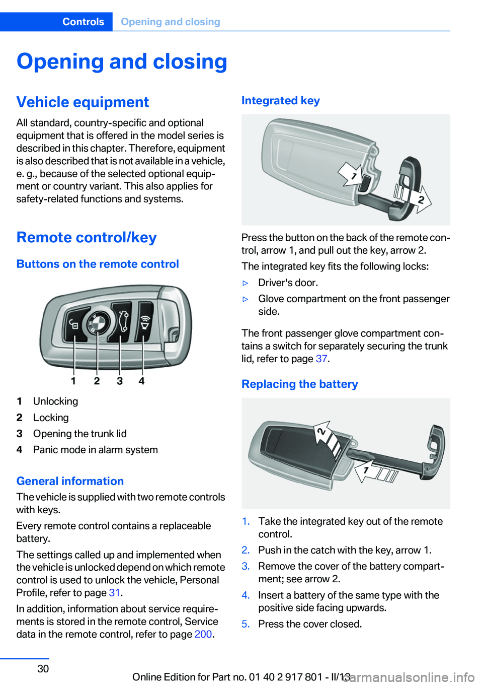
Buttons on the remote control1Unlocking2Locking3Opening the trunk lid4Panic mode in alarm system
General information
The vehicle is supplied with two remote controls
with keys.
Every remote control contains a replaceable
battery.
The settings called up and implemented when
the vehicle is unlocked depend on which remote
control is used to unlock the vehicle, Personal
Profile, refer to page 31.
In addition, information about service require‐
ments is stored in the remote control, Service
data in the remote control, refer to page 200.
Integrated key
Press the button on the back of the remote con‐
trol, arrow 1, and pull out the key, arrow 2.
The integrated key fits the following locks:
▷Driver's door.▷Glove compartment on the front passenger
side.
The front passenger glove compartment con‐
tains a switch for separately securing the trunk
lid, refer to page 37.
Replacing the battery
1.Take the integrated key out of the remote
control.2.Push in the catch with the key, arrow 1.3.Remove the cover of the battery compart‐
ment; see arrow 2.4.Insert a battery of the same type with the
positive side facing upwards.5.Press the cover closed.Seite 30ControlsOpening and closing30
Online Edition for Part no. 01 40 2 917 801 - II/13
Page 32 of 242
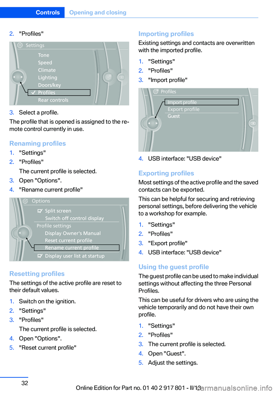
2."Profiles"3.Select a profile.
The profile that is opened is assigned to the re‐
mote control currently in use.
Renaming profiles
1."Settings"2."Profiles"
The current profile is selected.3.Open "Options".4."Rename current profile"
Resetting profiles
The settings of the active profile are reset to
their default values.
1.Switch on the ignition.2."Settings"3."Profiles"
The current profile is selected.4.Open "Options".5."Reset current profile"Importing profiles
Existing settings and contacts are overwritten
with the imported profile.1."Settings"2."Profiles"3."Import profile"4.USB interface: "USB device"
Exporting profiles
Most settings of the active profile and the saved
contacts can be exported.
This can be helpful for securing and retrieving
personal settings, before delivering the vehicle
to a workshop for example.
1."Settings"2."Profiles"3."Export profile"4.USB interface: "USB device"
Using the guest profile
The guest profile can be used to make individual
settings without affecting the three Personal
Profiles.
This can be useful for drivers who are using the
vehicle temporarily and do not have their own
profile.
1."Settings"2."Profiles"3.The current profile is selected.4.Open "Guest".5.Adjust the settings.Seite 32ControlsOpening and closing32
Online Edition for Part no. 01 40 2 917 801 - II/13
Page 36 of 242
▷LX8CAS2.▷MYTCAS4.
Compliance statement:
This device complies with part 15 of the FCC
Rules. Operation is subject to the following two
conditions:
▷This device may not cause harmful interfer‐
ence, and▷this device must accept any interference re‐
ceived, including interference that may
cause undesired operation.
Any unauthorized modifications or changes to
these devices could void the user's authority to
operate this equipment.
Using the door lock
General information
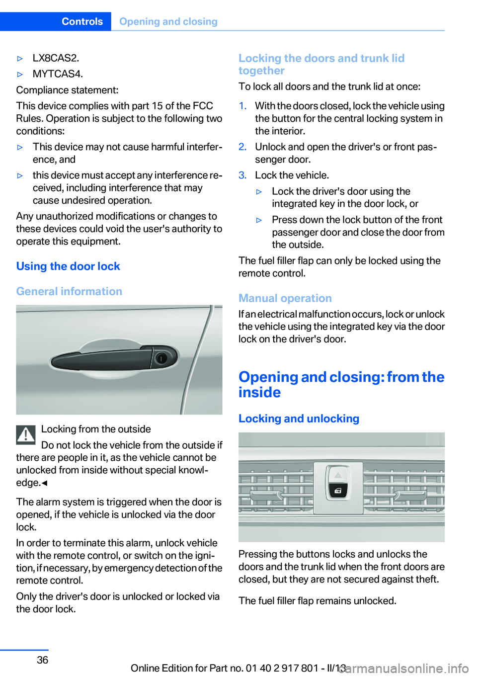
Locking from the outside
Do not lock the vehicle from the outside if
there are people in it, as the vehicle cannot be
unlocked from inside without special knowl‐
edge.◀
The alarm system is triggered when the door is
opened, if the vehicle is unlocked via the door
lock.
In order to terminate this alarm, unlock vehicle
with the remote control, or switch on the igni‐
tion, if necessary, by emergency detection of the
remote control.
Only the driver's door is unlocked or locked via
the door lock.
Locking the doors and trunk lid
together
To lock all doors and the trunk lid at once:1.With the doors closed, lock the vehicle using
the button for the central locking system in
the interior.2.Unlock and open the driver's or front pas‐
senger door.3.Lock the vehicle.▷Lock the driver's door using the
integrated key in the door lock, or▷Press down the lock button of the front
passenger door and close the door from
the outside.
The fuel filler flap can only be locked using the
remote control.
Manual operation
If an electrical malfunction occurs, lock or unlock
the vehicle using the integrated key via the door
lock on the driver's door.
Opening and closing: from the
inside
Locking and unlocking
Pressing the buttons locks and unlocks the
doors and the trunk lid when the front doors are
closed, but they are not secured against theft.
The fuel filler flap remains unlocked.
Seite 36ControlsOpening and closing36
Online Edition for Part no. 01 40 2 917 801 - II/13
Page 38 of 242
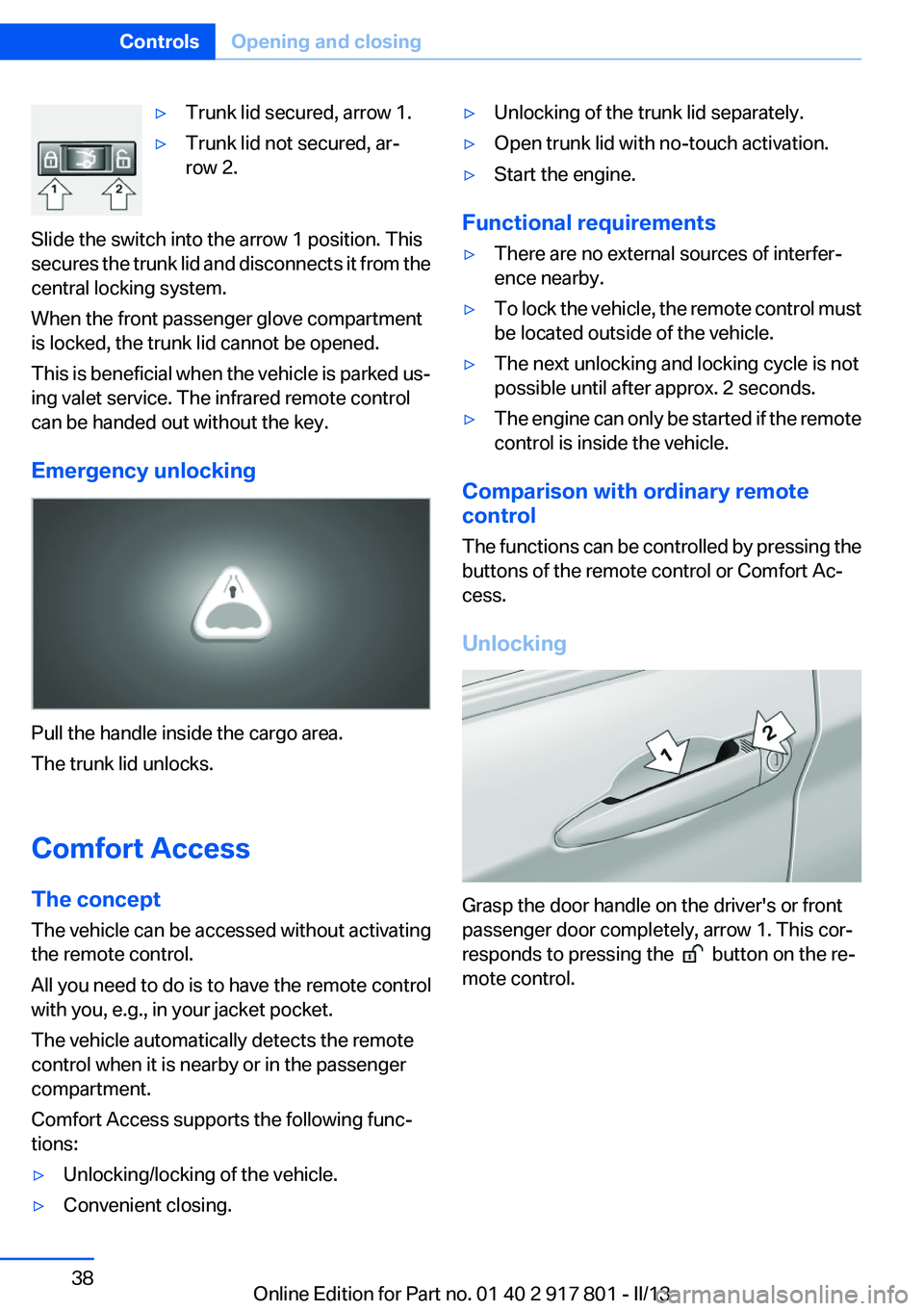
▷Trunk lid secured, arrow 1.▷Trunk lid not secured, ar‐
row 2.
Slide the switch into the arrow 1 position. This
secures the trunk lid and disconnects it from the
central locking system.
When the front passenger glove compartment
is locked, the trunk lid cannot be opened.
This is beneficial when the vehicle is parked us‐
ing valet service. The infrared remote control
can be handed out without the key.
Emergency unlocking
Pull the handle inside the cargo area.
The trunk lid unlocks.
Comfort Access
The concept
The vehicle can be accessed without activating
the remote control.
All you need to do is to have the remote control
with you, e.g., in your jacket pocket.
The vehicle automatically detects the remote
control when it is nearby or in the passenger
compartment.
Comfort Access supports the following func‐
tions:
▷Unlocking/locking of the vehicle.▷Convenient closing.▷Unlocking of the trunk lid separately.▷Open trunk lid with no-touch activation.▷Start the engine.
Functional requirements
▷There are no external sources of interfer‐
ence nearby.▷To lock the vehicle, the remote control must
be located outside of the vehicle.▷The next unlocking and locking cycle is not
possible until after approx. 2 seconds.▷The engine can only be started if the remote
control is inside the vehicle.
Comparison with ordinary remote
control
The functions can be controlled by pressing the
buttons of the remote control or Comfort Ac‐
cess.
Unlocking
Grasp the door handle on the driver's or front
passenger door completely, arrow 1. This cor‐
responds to pressing the
button on the re‐
mote control.
Seite 38ControlsOpening and closing38
Online Edition for Part no. 01 40 2 917 801 - II/13
Page 56 of 242
Deactivating the front passenger airbags
If a child restraint fixing system is used in
the front passenger seat, the front passenger
airbags must be deactivated; otherwise, there is
an increased risk of injury to the child when the
airbags are triggered, even with a child restraint
fixing system.◀
Seat position and height
Before installing a child restraint fixing system,
move the front passenger seat as far back as
possible and adjust its height to the highest po‐
sition to obtain the best possible position for the
belt and to offer optimal protection in the event
of an accident.
Do not change the seat position and height after
this.
Backrest width
Adjustable backrest width: before installing a
child restraint fixing system in the front passen‐
ger seat, open the backrest width completely.
Do not change the backrest width again and do
not call up a memory position.
Backrest width for the child seat
Before installing a child restraint fixing
system in the front passenger seat, the backrest
width must be opened completely. Do not
change the adjustment after this; otherwise, the
stability of the child seat will be reduced.◀Child seat security
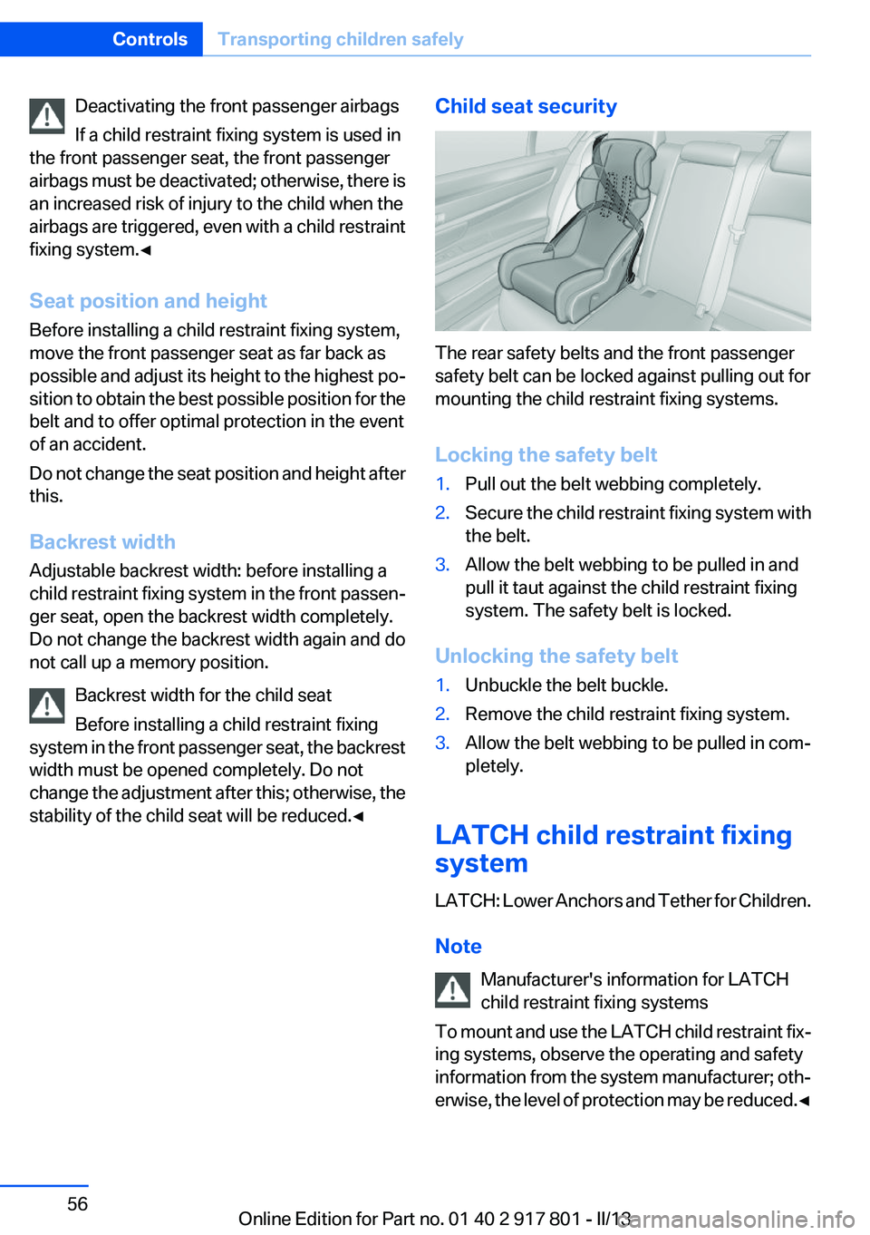
The rear safety belts and the front passenger
safety belt can be locked against pulling out for
mounting the child restraint fixing systems.
Locking the safety belt
1.Pull out the belt webbing completely.2.Secure the child restraint fixing system with
the belt.3.Allow the belt webbing to be pulled in and
pull it taut against the child restraint fixing
system. The safety belt is locked.
Unlocking the safety belt
1.Unbuckle the belt buckle.2.Remove the child restraint fixing system.3.Allow the belt webbing to be pulled in com‐
pletely.
LATCH child restraint fixing
system
LATCH: Lower Anchors and Tether for Children.
Note Manufacturer's information for LATCH
child restraint fixing systems
To mount and use the LATCH child restraint fix‐
ing systems, observe the operating and safety
information from the system manufacturer; oth‐
erwise, the level of protection may be reduced. ◀
Seite 56ControlsTransporting children safely56
Online Edition for Part no. 01 40 2 917 801 - II/13
Page 57 of 242
Mounts for the lower LATCH anchors
The lower anchors may be used to attach the
CRS to the vehicle seat up to a combined child
and CRS weight of 65 lb when the child is restr-
ained by the internal harnesses.
Correctly engage the lower LATCH an‐
chors
Make sure that the lower LATCH anchors have
properly engaged and that the child restraint fix‐
ing system is resting snugly against the back‐
rest; otherwise, the degree of protection offered
may be reduced.◀
Before mounting the LATCH child restraint fix‐
ing system, pull the belt away from the child re‐
straint fixing system.
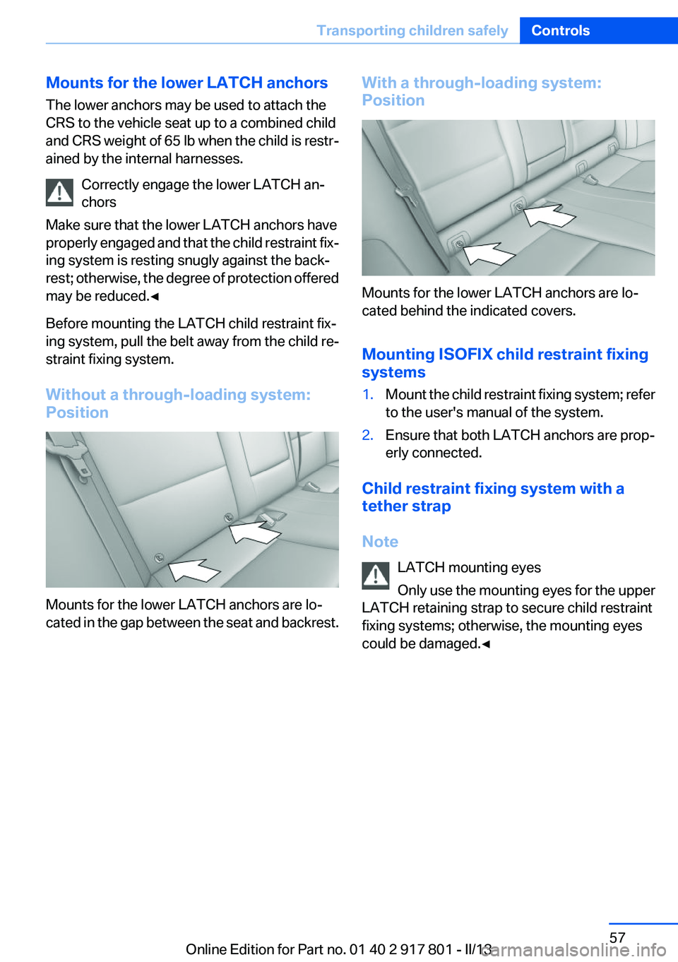
Without a through-loading system:
Position
Mounts for the lower LATCH anchors are lo‐
cated in the gap between the seat and backrest.
With a through-loading system:
Position
Mounts for the lower LATCH anchors are lo‐
cated behind the indicated covers.
Mounting ISOFIX child restraint fixing
systems
1.Mount the child restraint fixing system; refer
to the user's manual of the system.2.Ensure that both LATCH anchors are prop‐
erly connected.
Child restraint fixing system with a
tether strap
Note LATCH mounting eyes
Only use the mounting eyes for the upper
LATCH retaining strap to secure child restraint
fixing systems; otherwise, the mounting eyes
could be damaged.◀
Seite 57Transporting children safelyControls57
Online Edition for Part no. 01 40 2 917 801 - II/13
Page 58 of 242
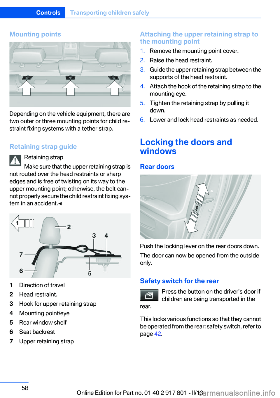
Mounting points
Depending on the vehicle equipment, there are
two outer or three mounting points for child re‐
straint fixing systems with a tether strap.
Retaining strap guide Retaining strap
Make sure that the upper retaining strap is
not routed over the head restraints or sharp
edges and is free of twisting on its way to the
upper mounting point; otherwise, the belt can‐
not properly secure the child restraint fixing sys‐
tem in an accident.◀
1Direction of travel2Head restraint.3Hook for upper retaining strap4Mounting point/eye5Rear window shelf6Seat backrest7Upper retaining strapAttaching the upper retaining strap to
the mounting point1.Remove the mounting point cover.2.Raise the head restraint.3.Guide the upper retaining strap between the
supports of the head restraint.4.Attach the hook of the retaining strap to the
mounting eye.5.Tighten the retaining strap by pulling it
down.6.Lower and lock head restraints as needed.
Locking the doors and
windows
Rear doors
Push the locking lever on the rear doors down.
The door can now be opened from the outside
only.
Safety switch for the rear Press the button on the driver's door if
children are being transported in the
rear.
This locks various functions so that they cannot
be operated from the rear: safety switch, refer to
page 42.
Seite 58ControlsTransporting children safely58
Online Edition for Part no. 01 40 2 917 801 - II/13
Page 61 of 242
Engine stop
General information Take the remote control with you
Take the remote control with you when
leaving the vehicle so that children, for example,
cannot start the engine.◀
Set the parking brake and further secure
the vehicle as required
Set the parking brake firmly when parking; oth‐
erwise, the vehicle could roll. On steep upward
and downward inclines, further secure the vehi‐
cle, for example, by turning the steering wheel in
the direction of the curb. ◀
Before driving into a car wash
In order for the vehicle to be able to roll into a car
wash, heed the information regarding Washing
in automatic car washes, refer to page 219.
Manual transmission
Switching off the engine1.With the vehicle at a standstill, press the
Start/Stop button.2.Shift into first gear or reverse.3.Set the parking brake.
Automatic transmission
Switching off the engine
1.Engage transmission position P with the ve‐
hicle stopped.2.Press the Start/Stop button.
The engine is switched off.
The radio ready state is switched on.3.Set the parking brake.Auto Start/Stop function
The concept
The Auto Start/Stop function helps save fuel.
The system switches off the engine during a
stop, e.g., in a traffic congestion or at traffic
lights. The ignition remains switched on. The
engine starts again automatically for driving off.
Certain vehicle components may experience
additional wear as a result of this system.
Automatic mode
The Auto Start/Stop function is operational after
each engine start.
This function is activated at speeds faster than
about 3 mph, approx. 5 km/h.
Engine stop
The engine is switched off automatically during
a stop under the following conditions:
Manual transmission:▷Neutral is engaged and the clutch pedal is
not pressed.▷The driver's safety belt is buckled or the
driver's door is closed.
Automatic transmission:
▷The selector lever is in transmission position
D.▷Brake pedal remains depressed while the
vehicle is stopped.▷The driver's safety belt is buckled or the
driver's door is closed.
The air flow of the air conditioner is reduced
when the engine is switched off.
Displays in the instrument cluster The READY display in the tach‐
ometer signals that the Auto
Start/Stop function is ready to
start the engine automatically.
Seite 61DrivingControls61
Online Edition for Part no. 01 40 2 917 801 - II/13