ESP BMW 328I COUPE 2009 E92 Owner's Guide
[x] Cancel search | Manufacturer: BMW, Model Year: 2009, Model line: 328I COUPE, Model: BMW 328I COUPE 2009 E92Pages: 260, PDF Size: 7.95 MB
Page 71 of 260
Controls
69Reference
At a glance
Driving tips
Communications
Navigation
Entertainment
Mobility
Everything under control
Odometer, outside
temperature display, clock
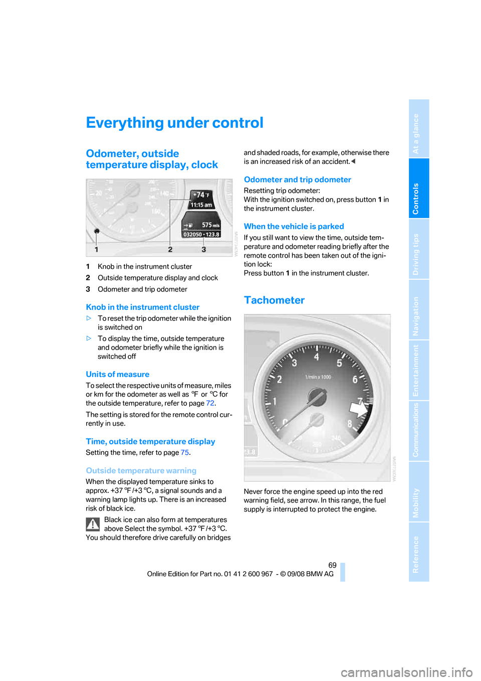
1Knob in the instrument cluster
2Outside temperature display and clock
3Odometer and trip odometer
Knob in the instrument cluster
>To reset the trip odometer while the ignition
is switched on
>To display the time, outside temperature
and odometer briefly while the ignition is
switched off
Units of measure
To select the respective units of measure, miles
or km for the odometer as well as 7 or 6 for
the outside temperature, refer to page72.
The setting is stored for the remote control cur-
rently in use.
Time, outside temperature display
Setting the time, refer to page75.
Outside temperature warning
When the displayed temperature sinks to
approx. +377/+36, a signal sounds and a
warning lamp lights up. There is an increased
risk of black ice.
Black ice can also form at temperatures
above Select the symbol. +377/+36.
You should therefore drive carefully on bridges and shaded roads, for example, otherwise there
is an increased risk of an accident.<
Odometer and trip odometer
Resetting trip odometer:
With the ignition switched on, press button1 in
the instrument cluster.
When the vehicle is parked
If you still want to view the time, outside tem-
perature and odometer reading briefly after the
remote control has been taken out of the igni-
tion lock:
Press button 1 in the instrument cluster.
Tachometer
Never force the engine speed up into the red
warning field, see arrow. In this range, the fuel
supply is interrupted to protect the engine.
Page 72 of 260
Everything under control
70
Coolant temperature
A warning lamp will come on if the coolant, and
therefore the engine, becomes too hot. In addi-
tion, a message will appear on the Control Dis-
play.
Check coolant level, refer to page210.
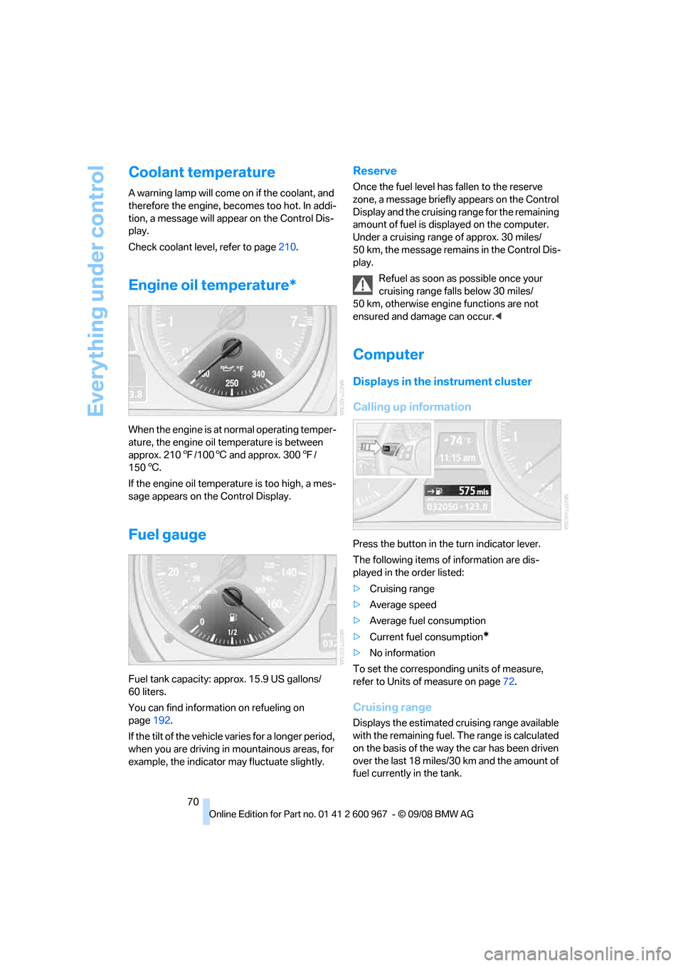
Engine oil temperature*
When the engine is at normal operating temper-
ature, the engine oil temperature is between
approx. 2107/1006 and approx. 3007/
1506.
If the engine oil temperature is too high, a mes-
sage appears on the Control Display.
Fuel gauge
Fuel tank capacity: approx. 15.9 US gallons/
60 liters.
You can find information on refueling on
page192.
If the tilt of the vehicle varies for a longer period,
when you are driving in mountainous areas, for
example, the indicator may fluctuate slightly.
Reserve
Once the fuel level has fallen to the reserve
zone, a message briefly appears on the Control
Display and the cruising range for the remaining
amount of fuel is displayed on the computer.
Under a cruising range of approx. 30 miles/
50 km, the message remains in the Control Dis-
play.
Refuel as soon as possible once your
cruising range falls below 30 miles/
50 km, otherwise engine functions are not
ensured and damage can occur.<
Computer
Displays in the instrument cluster
Calling up information
Press the button in the turn indicator lever.
The following items of information are dis-
played in the order listed:
>Cruising range
>Average speed
>Average fuel consumption
>Current fuel consumption
*
>No information
To set the corresponding units of measure,
refer to Units of measure on page72.
Cruising range
Displays the estimated cruising range available
with the remaining fuel. The range is calculated
on the basis of the way the car has been driven
over the last 18 miles/30 km and the amount of
fuel currently in the tank.
Page 73 of 260
Controls
71Reference
At a glance
Driving tips
Communications
Navigation
Entertainment
Mobility
Refuel as soon as possible once your
cruising range falls below 30 miles/
50 km, otherwise engine functions are not
ensured and damage can occur.<
Average speed
Periods with the vehicle parked and the engine
switched off are not included in the calculations
of average speed.
With the trip computer, refer to page72, you
can have the average speed for another trip dis-
played.
To reset average speed: press the button in the
turn indicator lever for approx. 2 seconds.
Average fuel consumption
The average fuel consumption is calculated for
the time during which the engine is running.
With the trip computer, refer to page72, you
can have the average consumption for another
trip displayed.
To reset average fuel consumption: press the
button in the turn indicator lever for approx.
2seconds.
Current fuel consumption
Displays the current fuel consumption. This
allows you to see whether your current driving
style is conducive to fuel economy with mini-
mum exhaust emissions.
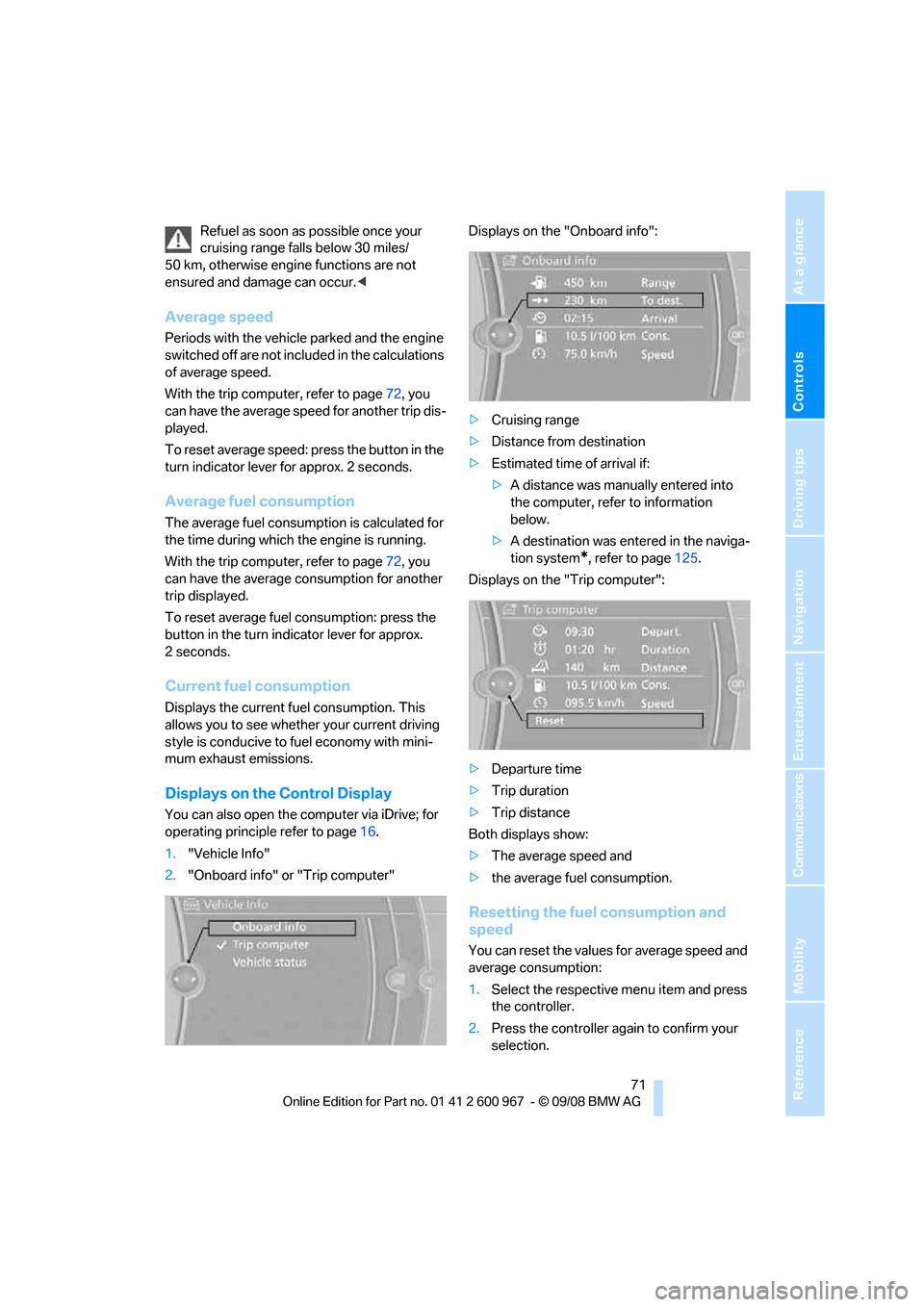
Displays on the Control Display
You can also open the computer via iDrive; for
operating principle refer to page16.
1."Vehicle Info"
2."Onboard info" or "Trip computer"Displays on the "Onboard info":
>Cruising range
>Distance from destination
>Estimated time of arrival if:
>A distance was manually entered into
the computer, refer to information
below.
>A destination was entered in the naviga-
tion system
*, refer to page125.
Displays on the "Trip computer":
>Departure time
>Trip duration
>Trip distance
Both displays show:
>The average speed and
>the average fuel consumption.
Resetting the fuel consumption and
speed
You can reset the values for average speed and
average consumption:
1.Select the respective menu item and press
the controller.
2.Press the controller again to confirm your
selection.
Page 75 of 260
Controls
73Reference
At a glance
Driving tips
Communications
Navigation
Entertainment
Mobility
1."Settings"
2."Language/Units"
3.Select the desired menu item.
4.Select the desired unit.
The settings are stored for the remote control
currently in use.
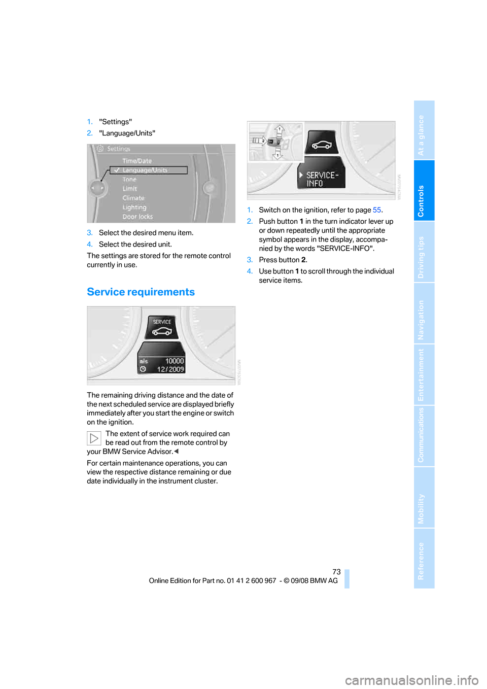
Service requirements
The remaining driving distance and the date of
the next scheduled service are displayed briefly
immediately after you start the engine or switch
on the ignition.
The extent of service work required can
be read out from the remote control by
your BMW Service Advisor.<
For certain maintenance operations, you can
view the respective distance remaining or due
date individually in the instrument cluster.1.Switch on the ignition, refer to page55.
2.Push button 1 in the turn indicator lever up
or down repeatedly until the appropriate
symbol appears in the display, accompa-
nied by the words "SERVICE-INFO".
3.Press button 2.
4.Use button 1 to scroll through the individual
service items.
Page 80 of 260
Everything under control
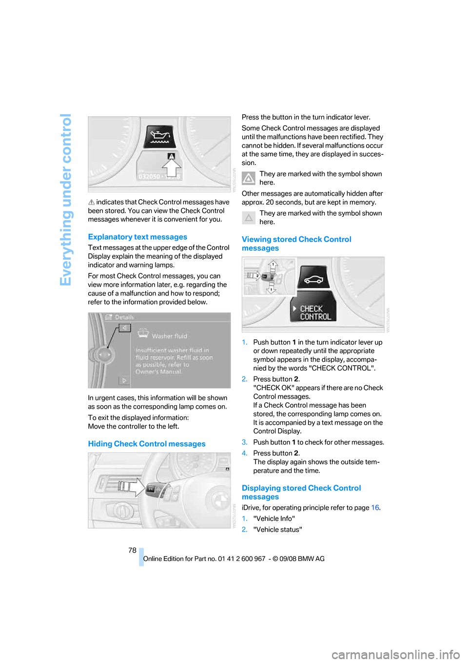
78 indicates that Check Control messages have
been stored. You can view the Check Control
messages whenever it is convenient for you.
Explanatory text messages
Text messages at the upper edge of the Control
Display explain the meaning of the displayed
indicator and warning lamps.
For most Check Control messages, you can
view more information later, e.g. regarding the
cause of a malfunction and how to respond;
refer to the information provided below.
In urgent cases, this information will be shown
as soon as the corresponding lamp comes on.
To exit the displayed information:
Move the controller to the left.
Hiding Check Control messages
Press the button in the turn indicator lever.
Some Check Control messages are displayed
until the malfunctions have been rectified. They
cannot be hidden. If several malfunctions occur
at the same time, they are displayed in succes-
sion.
They are marked with the symbol shown
here.
Other messages are automatically hidden after
approx. 20 seconds, but are kept in memory.
They are marked with the symbol shown
here.
Viewing stored Check Control
messages
1.Push button 1 in the turn indicator lever up
or down repeatedly until the appropriate
symbol appears in the display, accompa-
nied by the words "CHECK CONTROL".
2.Press button 2.
"CHECK OK" appears if there are no Check
Control messages.
If a Check Control message has been
stored, the corresponding lamp comes on.
It is accompanied by a text message on the
Control Display.
3.Push button 1 to check for other messages.
4.Press button 2.
The display again shows the outside tem-
perature and the time.
Displaying stored Check Control
messages
iDrive, for operating principle refer to page16.
1."Vehicle Info"
2."Vehicle status"
Page 84 of 260
Technology for driving comfort and safety
82
Technology for driving comfort and safety
Park Distance Control PDC*
The concept
The PDC assists you with maneuvering in tight
parking spaces. Acoustic signals and a visual
indicator
warn you of the presence of an object
behind your vehicle. To measure the distance,
there are four ultrasonic sensors in either
bumper.
These sensors have a range of approx. 6.5 ft/
2 m. However, an acoustic warning does not
sound until an object is approx. 24 in/60 cm
from the corner sensors, or approx. 5 ft/1.50 m
from the center sensors.
PDC is a parking aid that can indicate
objects when they are approached
slowly, as is usually the case when parking.
Avoid approaching an object at high speed, oth-
erwise physical circumstances may lead to the
system warning being issued too late.<
Switching on automatically
With the engine running or the ignition switched
on, the system is activated approx. 1 second
after you engage reverse gear or selector lever
or transmission position R. Wait this short
period before driving.
Switching off automatically
After approx. 165 ft/50 m of driving or above
approx. 20 mph/approx. 30 km/h, the system
switches off and the LED goes out.
Signal tones
When nearing an object, its position is indicated
correspondingly by an interval tone. As the dis-
tance between vehicle and object decreases,
the intervals between the tones become
shorter. If the distance to the nearest object
falls to below roughly 1 ft/30 cm, then a contin-
uous tone sounds.
An interval tone is interrupted after approx.
3seconds>if you remain in front of an object that has
been detected by only one of the corner
sensors
>if you are driving parallel to a wall.
Malfunction
The indicator lamp in the instrument
cluster comes on. PDC is malfunc-
tioning. A message appears on the
Control Display. Have the system checked.
To avoid this problem, keep the sensors clean
and free of ice or snow in order to ensure that
they will continue to operate effectively. When
using a high-pressure cleaner, do not spray the
sensors for extended periods of time and only
from a distance of at least 4 in/10 cm.
PDC with visual warning
The approach of the vehicle to an object is
shown on the Control Display. Objects that are
farther away are displayed on the Control Dis-
play before a signal tone sounds. The display
appears on the Control Display as soon as PDC
is activated.
System limitations
Even with PDC, final responsibility for
estimating the distance between the
vehicle and any obstructions always remains
with the driver. Even when sensors are pro-
vided, there is a blind spot in which objects can
no longer be detected. The system is also sub-
ject to the physical limits that apply to all forms
of ultrasonic measurement, such as those
encountered with trailer towbars and hitches,
thin or wedge-shaped objects, etc. Low objects
that have already been displayed, e.g. curbs,
can disappear again from the detection area of
the sensors before or after a continuous tone
sounds. Higher, protruding objects, e.g. ledges,
cannot be detected. Therefore, always drive
cautiously, otherwise there is a risk of personal
injury or property damage.
Loud sound sources outside or inside the car
Page 85 of 260
Controls
83Reference
At a glance
Driving tips
Communications
Navigation
Entertainment
Mobility
can drown out the PDC signal. Therefore,
always drive cautiously, otherwise there is a risk
of personal injury or property damage.<
Driving stability control
systems
Your BMW has a number of systems that help
to maintain the vehicle's stability even in
adverse driving conditions.
Antilock Brake System ABS
ABS prevents locking of the wheels during
braking. Safe steering response is maintained
even during full braking. Active safety is thus
increased.
The ABS is operational every time you start the
engine. Braking safely, refer to page118.
Electronic brake-force distribution
The system controls the brake pressure in the
rear wheels to ensure stable braking behavior.
Dynamic Brake Control DBC
When you apply the brakes rapidly, this system
automatically produces the maximum braking
force boost and thus helps to achieve the short-
est possible braking distance during full brak-
ing. This system exploits all of the benefits pro-
vided by ABS.
Do not reduce the pressure on the brake for the
duration of the full braking application.
Dynamic Stability Control DSC
DSC prevents the driving wheels from losing
traction when you pull away from rest or accel-
erate. The system also recognizes unstable
driving conditions, for example if the rear of the
car is about to swerve or if momentum is acting
at an angle past the front wheels. In these
cases, DSC helps the vehicle maintain a safe
course within physical limits by reducing engine
output and through braking actions at the indi-
vidual wheels.
The laws of physics cannot be repealed,
even with DSC. An appropriate driving style always remains the responsibility of the
driver. Therefore, do not reduce the additional
s a f e t y m a r g i n a g a i n b y t a k i n g r i s k s , a s t h i s c o u l d
result in an accident.<
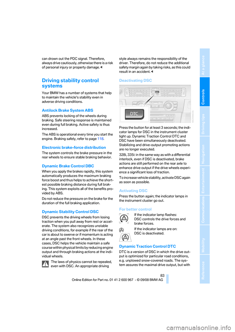
Deactivating DSC
Press the button for at least 3 seconds; the indi-
cator lamps for DSC in the instrument cluster
light up. Dynamic Traction Control DTC and
DSC have been simultaneously deactivated.
Stabilizing and drive-output promoting actions
are no longer executed.
328i, 335i: in the same way as with a differential
interlock, even if DSC is deactivated, brake
actions are still performed on the rear axle to
enhance drive output if the drive wheels experi-
ence a significant loss of traction.
To increase vehicle stability, activate DSC again
as soon as possible.
Activating DSC
Press the button again; the indicator lamps in
the instrument cluster go out.
For better control
If the indicator lamp flashes:
DSC controls the drive forces and
brake forces.
If the indicator lamps are on:
DSC is deactivated.
Dynamic Traction Control DTC
DTC is a version of DSC in which the drive out-
put is optimized for particular road conditions,
e.g. unplowed snow-covered roads. The sys-
tem assures the maximal drive output, but with
Page 89 of 260
Controls
87Reference
At a glance
Driving tips
Communications
Navigation
Entertainment
Mobility
Functional requirement
In order to assure the reliable reporting of a flat
tire, the system must be reset while all tire infla-
tion pressures are correct.
Always use wheels with TPM electronics. Oth-
erwise, the system may malfunction.
Each time a tire inflation pressure has
been corrected or a wheel or tire has been
changed, reset the system.<
System limitations
TPM cannot warn you in advance of sud-
den severe tire damage caused by out-
side influences.<
The system does not work correctly if it has not
been reset; for example, a flat tire may be indi-
cated even though the tire inflation pressures
are correct.
The system is inactive and cannot indicate a flat
tire if a wheel without TPM electronics, such as
a compact spare wheel, has been mounted, or if
TPM is temporarily malfunctioning due to other
systems or devices using the same radio fre-
quency.
Status indicator on the Control Display
The color of the tires represents the status of
the tires and the system.
TPM takes into account that tire pressures
change while the vehicle is being driven. The
tire pressures do not need to be corrected
unless the TPM instructs you to do so by means
of color indicators.
Green
The tire inflation pressure corresponds to the
established target value.
"TPM active" appears on the Control Display.
One wheel yellow
There is a flat tire or substantial loss of tire pres-
sure in the indicated tire. A message appears on
the Control Display.
All wheels yellow
There is a flat tire or substantial loss of tire pres-
sure in several tires. A message appears on the
Control Display.
Gray
The system cannot detect a puncture.
Possible reasons for this:
>TPM is being reset
>Temporary malfunction caused by systems
or devices using the same radio frequency
>Malfunction
Resetting the system
Each time a tire inflation pressure has
been corrected or a wheel or tire has been
changed, reset the system.<
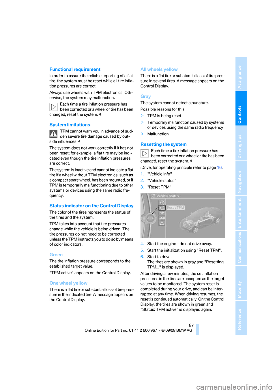
iDrive, for operating principle refer to page16.
1."Vehicle Info"
2."Vehicle status"
3."Reset TPM"
4.Start the engine - do not drive away.
5.Start the initialization using "Reset TPM".
6.Start to drive.
The tires are shown in gray and "Resetting
TPM..." is displayed.
After driving a few minutes, the set inflation
pressures in the tires are accepted as the target
values to be monitored. The system reset is
completed during your drive, and can be inter-
rupted at any time. When driving resumes, the
reset is continued automatically. On the Control
Display, the tires are shown in green and
"Status: TPM active" is displayed again.
Page 91 of 260
Controls
89Reference
At a glance
Driving tips
Communications
Navigation
Entertainment
Mobility
stop and check your tires as soon as possible,
and inflate them to the proper pressure. Driving
on a significantly underinflated tire causes the
tire to overheat and can lead to tire failure.
Underinflation also reduces fuel efficiency and
tire tread life, and may affect the vehicle’s han-
dling and stopping ability. Please note that the
TPMS is not a substitute for proper tire mainte-
nance, and it is the driver’s responsibility to
maintain correct tire pressure, even if underin-
flation has not reached the level at which the
TPMS low tire pressure telltale illuminates.
The TPMS malfunction indicator is combined
with the low tire pressure telltale. When the sys-
tem detects a malfunction, the telltale will flash
for approximately one minute and then remain
continuously lit. This sequence will continue
upon subsequent vehicle startups as long as
the malfunction exists. When the malfunction
indicator is illuminated, the system may not be
able to detect or signal low tire pressure as
intended. TPMS malfunctions may occur for a
variety of reasons, including the installation of
replacement or alternate tires or wheels on the
vehicle that prevent the TPMS from functioning
properly. Always check the TPMS malfunction
telltale after replacing one or more tires or
wheels on your vehicle to ensure that the
replacement or alternate tires and wheels allow
the TPMS to continue to function properly.
Active steering*
The concept
Active steering varies the turning angle of the
front wheels in relation to steering wheel move-
ments. It also varies the steering force required
to turn the wheels depending on the speed at
which you are driving.
When you are driving in the low road-speed
range, e.g. in a town or when parking, the steer-
ing angle increases, i.e. the steering becomes
very direct, and less effort is required to turn the
wheels. In the higher speed range, on the other
hand, the steering angle is reduced more and
more. This improves the handling capability of
your BMW over the entire speed range.In critical situations, the system can make tar-
geted corrections to the steering angle pro-
vided by the driver and thus stabilize the vehicle
before the driver intervenes. This stabilizing
intervention is simultaneously deactivated
when DSC is switched off, refer to page83.
Malfunction
The warning lamps come on. Active
steering is no longer operational. At
low speeds, greater steering wheel
movements are required, whereas at
higher speeds the vehicle reacts more sensi-
tively to steering wheel movements. The stabil-
ity-enhancing feature may also be deactivated.
Drive cautiously and think well ahead. Have the
system checked.
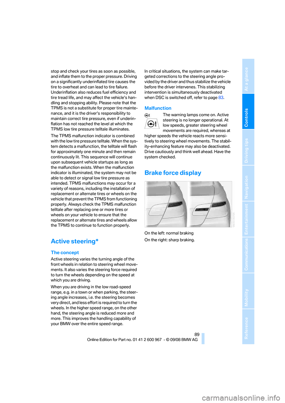
Brake force display
On the left: normal braking
On the right: sharp braking.
Page 92 of 260
Technology for driving comfort and safety
90
Airbags
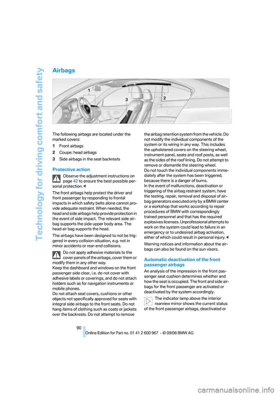
The following airbags are located under the
marked covers:
1Front airbags
2Coupe: head airbags
3Side airbags in the seat backrests
Protective action
Observe the adjustment instructions on
page42 to ensure the best possible per-
sonal protection.<
The front airbags help protect the driver and
front passenger by responding to frontal
impacts in which safety belts alone cannot pro-
vide adequate restraint. When needed, the
head and side airbags help provide protection in
the event of side impact. The relevant side air-
bag supports the side upper body area. The
head air bag supports the head.
The airbags have been designed to not be trig-
gered in every collision situation, e.g. not in
minor accidents or rear-end collisions.
Do not apply adhesive materials to the
cover panels of the airbags, cover them or
modify them in any other way.
Keep the dashboard and windows on the front
passenger side clear, i.e. do not cover with
adhesive labels or coverings, and do not attach
holders such as for navigation instruments or
mobile phones.
Do not attach seat covers, cushions or other
objects not specifically approved for seats with
integral side airbags to the front seats. Do not
hang items of clothing such as coats or jackets
over the backrests. Do not attempt to remove the airbag retention system from the vehicle. Do
not modify the individual components of the
system or its wiring in any way. This includes
the upholstered covers on the steering wheel,
instrument panel, seats and roof posts, as well
as the sides of the roof lining. Do not attempt to
remove or dismantle the steering wheel.
Do not touch the individual components imme-
diately after the system has been triggered,
because there is a danger of burns.
In the event of malfunctions, deactivation or
triggering of the airbag restraint system, have
the testing, repair, removal and disposal of air-
bag generators executed only by a BMW center
or a workshop that works according to repair
procedures of BMW with correspondingly
trained personnel and that has the required
explosives licenses. Unprofessional attempts to
work on the system could lead to failure in an
emergency or to undesired airbag activation,
either of which could result in personal injury.<
Warning notices and information about the air-
bags can also be found on the sun visors.
Automatic deactivation of the front
passenger airbags
An analysis of the impression in the front pas-
senger seat cushion determines whether and
how the seat is occupied. The front and side air-
bags for the front passenger are activated or
deactivated by the system accordingly.
The indicator lamp above the interior
rearview mirror shows the current status
of the front passenger airbags, deactivated or