check engine light BMW 328I SEDAN 2012 Owners Manual
[x] Cancel search | Manufacturer: BMW, Model Year: 2012, Model line: 328I SEDAN, Model: BMW 328I SEDAN 2012Pages: 325, PDF Size: 12.26 MB
Page 44 of 325
middle of the opening in the roof, or from the
tilted position during closing.
The glass sunroof opens again slightly.
Danger of pinching even with pinch pro‐
tection
Despite the pinch protection system, check that
the roof's closing path is clear; otherwise, the
closing action may not be interrupted in certain
extreme situations, such as when thin objects
are present.◀
Closing without the pinch protection
system
For example, if there is an external danger, pro‐
ceed as follows:1.Press the switch forward beyond the resist‐
ance point and hold.
Pinch protection is limited and the roof re‐
opens slightly if the closing force exceeds a
certain value.2.Press the switch forward again beyond the
resistance point and hold until the roof
closes without pinch protection.
Initializing after a power failure
After a power failure during the opening or clos‐
ing process, the roof can only be operated to a
limited extent.
Initializing the system
The system can be initialized when the vehicle
is stationary and the engine is running.
During the initialization, the roof closes without
pinch protection.
Danger of pinching
Monitor the closing process and make
sure that the closing path of the glass sunroof is
clear; otherwise, injuries may result.◀
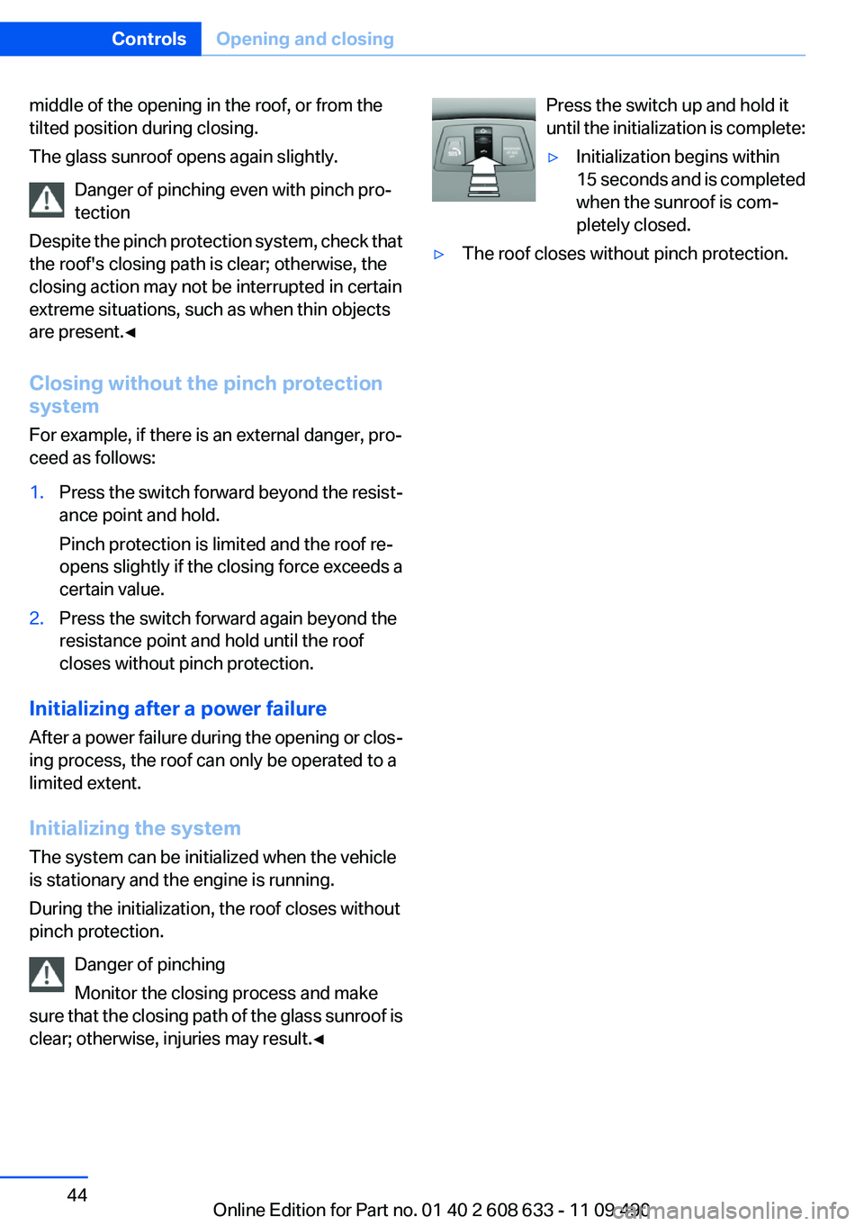
Press the switch up and hold it
until the initialization is complete:▷Initialization begins within
15 seconds and is completed
when the sunroof is com‐
pletely closed.▷The roof closes without pinch protection.Seite 44ControlsOpening and closing44
Online Edition for Part no. 01 40 2 608 633 - 11 09 490
Page 63 of 325
Preventing an engine stop using the
brake pedal
The engine stop can be actively prevented
within one second after the vehicle comes to a
standstill.▷Immediately after the vehicle comes to a
standstill, briefly press the brake pedal
forcefully.▷Then press the brake pedal with normal
braking force.
Activating/deactivating the system
manually
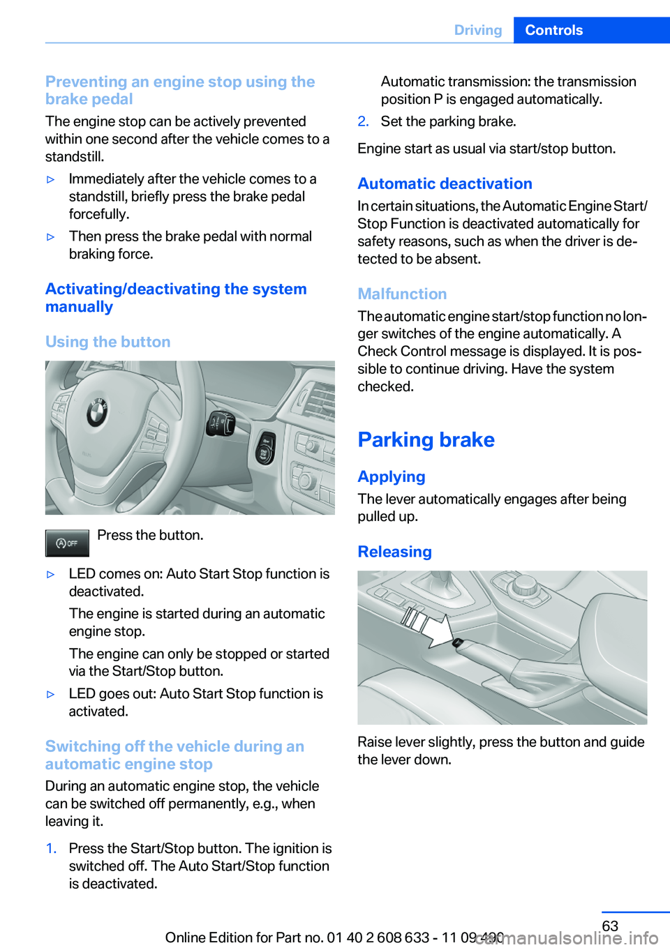
Using the button
Press the button.
▷LED comes on: Auto Start Stop function is
deactivated.
The engine is started during an automatic
engine stop.
The engine can only be stopped or started
via the Start/Stop button.▷LED goes out: Auto Start Stop function is
activated.
Switching off the vehicle during an
automatic engine stop
During an automatic engine stop, the vehicle
can be switched off permanently, e.g., when
leaving it.
1.Press the Start/Stop button. The ignition is
switched off. The Auto Start/Stop function
is deactivated.Automatic transmission: the transmission
position P is engaged automatically.2.Set the parking brake.
Engine start as usual via start/stop button.
Automatic deactivation
In certain situations, the Automatic Engine Start/
Stop Function is deactivated automatically for
safety reasons, such as when the driver is de‐
tected to be absent.
Malfunction
The automatic engine start/stop function no lon‐
ger switches of the engine automatically. A
Check Control message is displayed. It is pos‐
sible to continue driving. Have the system
checked.
Parking brake
Applying
The lever automatically engages after being
pulled up.
Releasing
Raise lever slightly, press the button and guide
the lever down.
Seite 63DrivingControls63
Online Edition for Part no. 01 40 2 608 633 - 11 09 490
Page 74 of 325
Several of the lamps are checked for proper
functioning and light up temporarily when the
engine is started or the ignition is switched on.
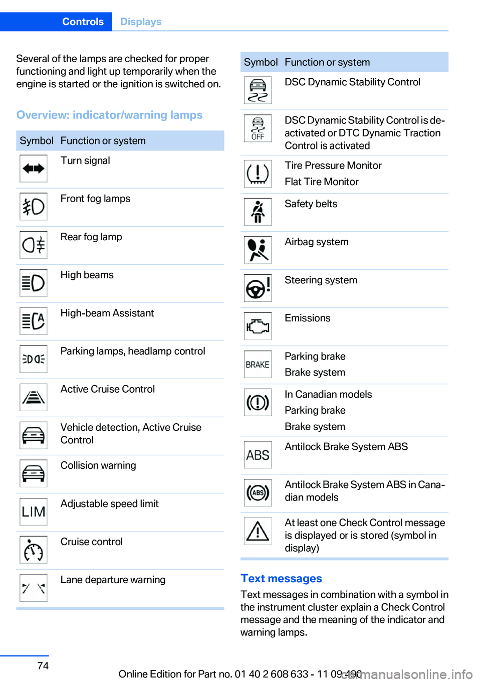
Overview: indicator/warning lampsSymbolFunction or systemTurn signalFront fog lampsRear fog lampHigh beamsHigh-beam AssistantParking lamps, headlamp controlActive Cruise ControlVehicle detection, Active Cruise
ControlCollision warningAdjustable speed limitCruise controlLane departure warningSymbolFunction or systemDSC Dynamic Stability ControlDSC Dynamic Stability Control is de‐
activated or DTC Dynamic Traction
Control is activatedTire Pressure Monitor
Flat Tire MonitorSafety beltsAirbag systemSteering systemEmissionsParking brake
Brake systemIn Canadian models
Parking brake
Brake systemAntilock Brake System ABSAntilock Brake System ABS in Cana‐
dian modelsAt least one Check Control message
is displayed or is stored (symbol in
display)
Text messages
Text messages in combination with a symbol in
the instrument cluster explain a Check Control
message and the meaning of the indicator and
warning lamps.
Seite 74ControlsDisplays74
Online Edition for Part no. 01 40 2 608 633 - 11 09 490
Page 95 of 325
A change in the tire inflation pressure during
driving is taken into account.
A correction is only necessary if this is indicated
by the TPM
Wheels, green
The tire inflation pressure is equal to the target
state.
One wheel is yellow
A flat tire or major drop in inflation pressure in
the indicated tire.
All wheels are yellow▷A flat tire or major drop in inflation pressure
in several tires.▷The system was not reset after a wheel
change and thus warns based on the infla‐
tion pressures initialized last.▷A flat tire in one or more tires while the sys‐
tem is being reset.
Wheels, gray
The system cannot detect a flat tire. Reasons for
this may be:
▷TPM is being reset.▷Disturbance by systems or devices with the
same radio frequency.▷Malfunction.
Resetting the system
Reset the system after each correction of the
tire inflation pressure and after every tire or
wheel change.
1."Vehicle Info"2."Vehicle status"3. "Reset"4.Start the engine - do not drive away.5.Reset the tire pressure using "Reset".6.Drive away.The tires are shown in gray and "Resetting
TPM..." is displayed.
After driving for a few minutes, the set tire infla‐
tion pressures are applied as set values. The re‐
setting process is completed automatically dur‐
ing driving. The tires are shown in green and
"TPM active" is shown on the Control Display.
The trip can be interrupted at any time. If you
drive away again, the process resumes auto‐
matically.
If a flat tire is detected during a reset, all tires are
displayed in yellow.
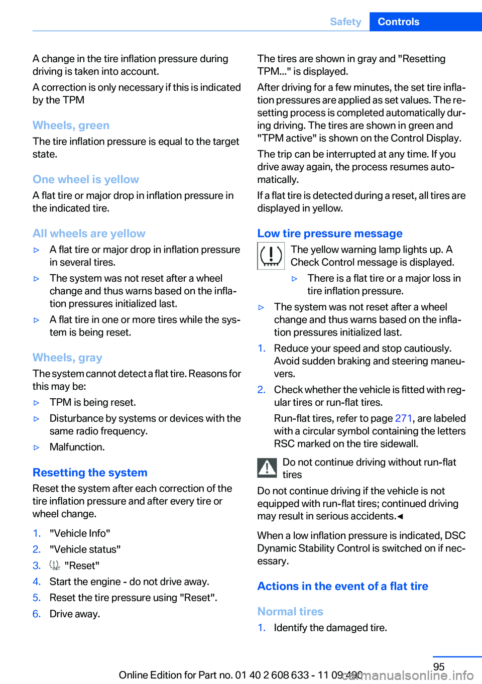
Low tire pressure message The yellow warning lamp lights up. A
Check Control message is displayed.▷There is a flat tire or a major loss in
tire inflation pressure.▷The system was not reset after a wheel
change and thus warns based on the infla‐
tion pressures initialized last.1.Reduce your speed and stop cautiously.
Avoid sudden braking and steering maneu‐
vers.2.Check whether the vehicle is fitted with reg‐
ular tires or run-flat tires.
Run-flat tires, refer to page 271, are labeled
with a circular symbol containing the letters
RSC marked on the tire sidewall.
Do not continue driving without run-flat
tires
Do not continue driving if the vehicle is not
equipped with run-flat tires; continued driving
may result in serious accidents.◀
When a low inflation pressure is indicated, DSC
Dynamic Stability Control is switched on if nec‐
essary.
Actions in the event of a flat tire
Normal tires
1.Identify the damaged tire.Seite 95SafetyControls95
Online Edition for Part no. 01 40 2 608 633 - 11 09 490
Page 98 of 325
A natural, even pressure loss in all four tires can‐
not be detected. Therefore, check the tire infla‐
tion pressure regularly.
The system could be delayed or malfunction in
the following situations:▷When the system has not been initialized.▷When driving on a snowy or slippery road
surface.▷Sporty driving style: slip in the drive wheels,
high lateral acceleration.▷When driving with snow chains.
Status display
The current status of the Flat Tire Monitor can
be displayed on the Control Display, e.g.,
whether or not the FTM is active.
1."Vehicle Info"2."Vehicle status"3. "Flat Tire Monitor"
The status is displayed.
Initialization
The initialization process adopts the set inflation
tire pressures as reference values for the detec‐
tion of a flat tire. Initialization is started by con‐
firming the inflation pressures.
Do not initialize the system when driving with
snow chains.
1."Vehicle Info"2."Vehicle status"3. "Reset"4.Start the engine - do not drive away.5.Start the initialization with "Reset".6.Drive away.
The initialization is completed while driving,
which can be interrupted at any time.
The initialization automatically continues when
driving resumes.
Indication of a flat tire
The yellow warning lamp lights up. A
Check Control message is displayed.
There is a flat tire or a major loss in tire
inflation pressure.1.Reduce your speed and stop cautiously.
Avoid sudden braking and steering maneu‐
vers.2.Check whether the vehicle is fitted with reg‐
ular tires or run-flat tires.
Run-flat tires, refer to page 271, are labeled
with a circular symbol containing the letters
RSC marked on the tire sidewall.
Do not continue driving without run-flat
tires
Do not continue driving if the vehicle is not
equipped with run-flat tires; continued driving
may result in serious accidents.◀
When a flat tire is indicated, DSC Dynamic Sta‐
bility Control is switched on if necessary.
Actions in the event of a flat tire
Normal tires
1.Identify the damaged tire.
Do this by checking the air pressure in all
four tires.
If the tire inflation pressure in all four tires is
correct, the Flat Tire Monitor may not have
been initialized. In this case, initialize the
system.
If an identification is not possible, please
contact the service center.2.Rectify the flat tire.
Run-flat tires
Maximum speed
You can continue driving with a damaged tire at
speeds up to 50 mph/80 km/h.
Seite 98ControlsSafety98
Online Edition for Part no. 01 40 2 608 633 - 11 09 490
Page 126 of 325
Top View
The concept
Top View assists you in parking and maneuver‐
ing. The area around the doors and the road area
around the vehicle are shown on the Control
Display for this purpose.
Capturing the image
The image is captured by two cameras
integrated in the exterior mirrors and by the
backup camera.
The range is at least 7 ft/2 m to the side and rear.
In this way, obstacles up to the height of the ex‐
terior mirrors are detected early.
System limits
Top View cannot be used in the following situa‐
tions:▷With a door open.▷With the trunk lid open.▷With an exterior mirror folded in.▷In poor light.
A Check Control message is displayed in some
of these situations.
Check the traffic situation as well
Check the traffic situation around the ve‐
hicle with your own eyes. Otherwise, an accident
could result from road users or objects located
outside the picture area of the cameras.◀
Switching on automatically
Select transmission position R with the engine
running.
The Top View and PDC images are displayed if
the system is switched on via iDrive.
Automatic deactivation during forward
travel
The system switches off when a certain driving
distance or speed is exceeded.
Switch the system back on if necessary.
Switching on/off manually
Press the button.
▷On: the LED lights up.▷Off: the LED goes out.
If Top View is displayed, switch on the backup
camera via the iDrive, refer to page 127.
Visual warning
The approach of the vehicle to an object can be
shown on the Control Display.
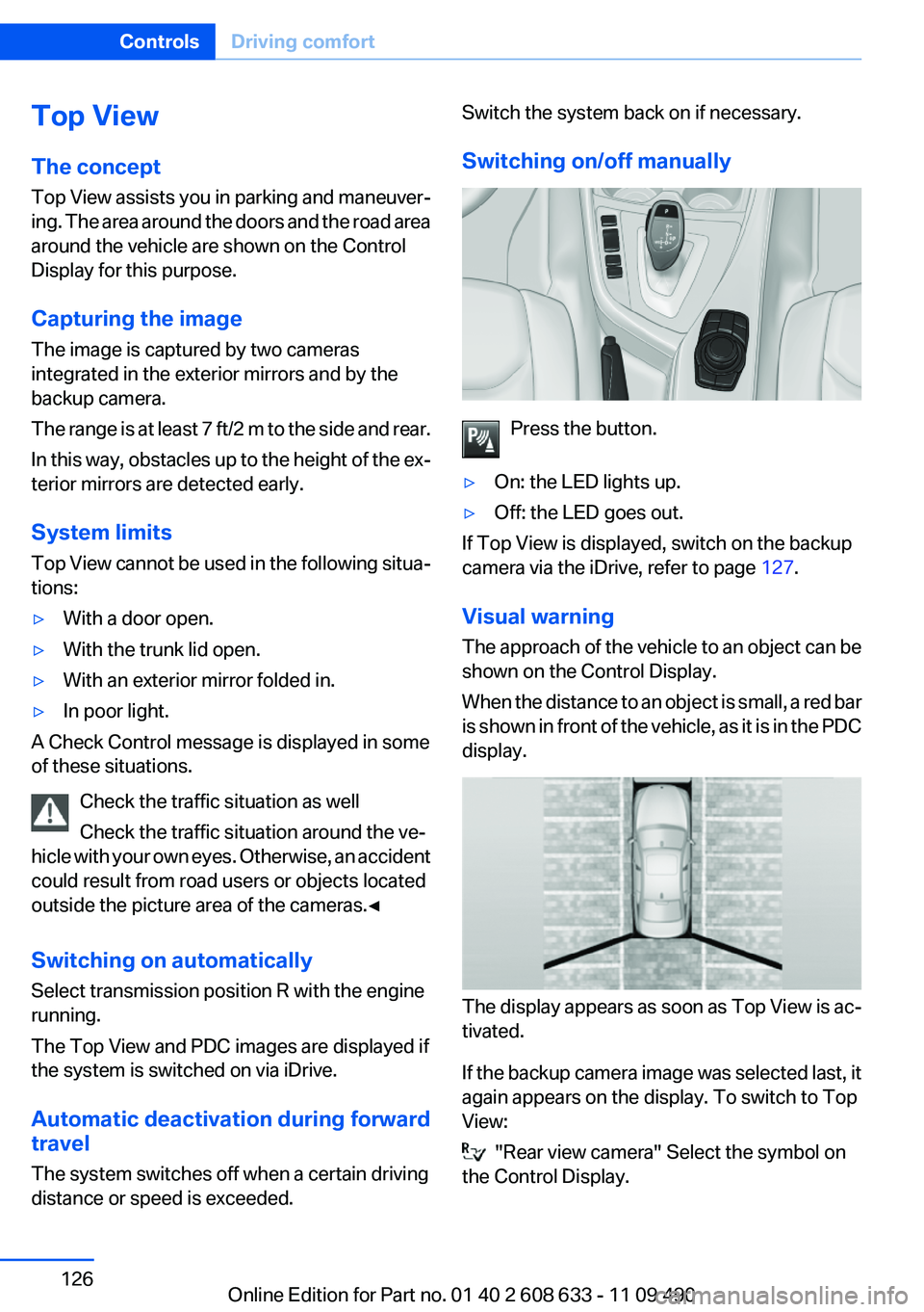
When the distance to an object is small, a red bar
is shown in front of the vehicle, as it is in the PDC
display.
The display appears as soon as Top View is ac‐
tivated.
If the backup camera image was selected last, it
again appears on the display. To switch to Top
View:
"Rear view camera" Select the symbol on
the Control Display.
Seite 126ControlsDriving comfort126
Online Edition for Part no. 01 40 2 608 633 - 11 09 490
Page 274 of 325
Engine oilVehicle equipment
All standard, country-specific and optional
equipment that is offered in the model series is
described in this chapter. Therefore, equipment
is also described that is not available in a vehicle,
e. g., because of the selected optional equip‐
ment or country variant. This also applies for
safety-related functions and systems.
General information
The engine oil consumption is dependent on the
driving style and driving conditions.
Therefore, regularly check the engine oil level
after refueling.
Check oil level
The concept
The oil level is monitored electronically during
driving and shown on the Control Display.
If the oil level reaches the minimum level, a
check control message is displayed.
Displaying the oil level1."Vehicle Info"2."Vehicle status"3. "Engine oil level"
Possible messages
▷"Engine oil level OK"▷"Engine oil at minimum. Add 1 quart of
engine oil!"
Within the next 125 miles/200 km, a maxi‐
mum of 1 US quart/liter oil.▷"Engine oil level below minimum. Add 1
quart!"
Immediately add 1 US quart/liter of oil.Detailed measurement
Requirements:▷Vehicle is on a level road and the engine is
running at operating temperature.▷Manual transmission: Shift lever in neutral
position clutch and gas pedal not de‐
pressed.▷Automatic transmission: Selector lever in
transmission position N or P and gas pedal
not depressed.
In order to perform a detailed measurement of
the engine oil level:
1."Vehicle Info"2."Vehicle status"3. "Measure engine oil level"4."Start measurement"
The oil level is checked and displayed via a scale.
During the detailed measurement, the idle
speed is increased somewhat.
Duration: approx. 1 minute.
Adding engine oil
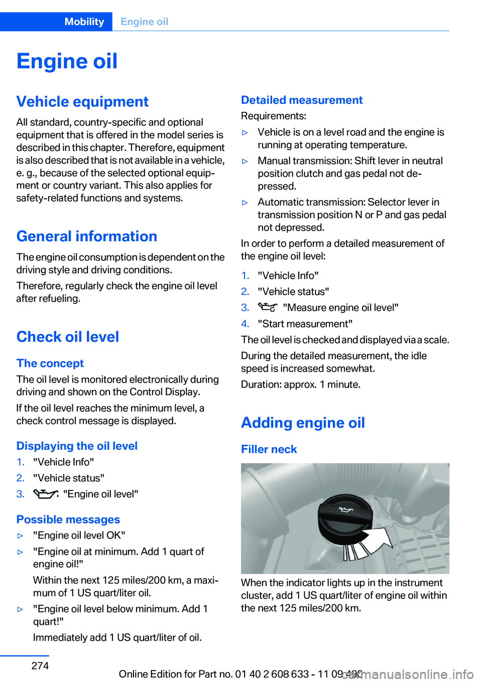
Filler neck
When the indicator lights up in the instrument
cluster, add 1 US quart/liter of engine oil within
the next 125 miles/200 km.
Seite 274MobilityEngine oil274
Online Edition for Part no. 01 40 2 608 633 - 11 09 490
Page 276 of 325
CoolantVehicle equipment
All standard, country-specific and optional
equipment that is offered in the model series is
described in this chapter. Therefore, equipment
is also described that is not available in a vehicle,
e. g., because of the selected optional equip‐
ment or country variant. This also applies for
safety-related functions and systems.
General information Danger of burns from hot engine
Do not open the cooling system while the
engine is hot; otherwise, escaping coolant may
cause burns.◀
Suitable additives
Only use suitable additives; otherwise, en‐
gine damage may occur. The additives are
harmful to your health.◀
Coolant consists of water and additives.
Not all commercially available additives are suit‐
able for your vehicle. Ask your service center for
suitable additives.
Coolant level
Checking1.Let the engine cool.2.The coolant level is correct if it lies between
the minimum and maximum marks. The
marks are on the side of the coolant reser‐
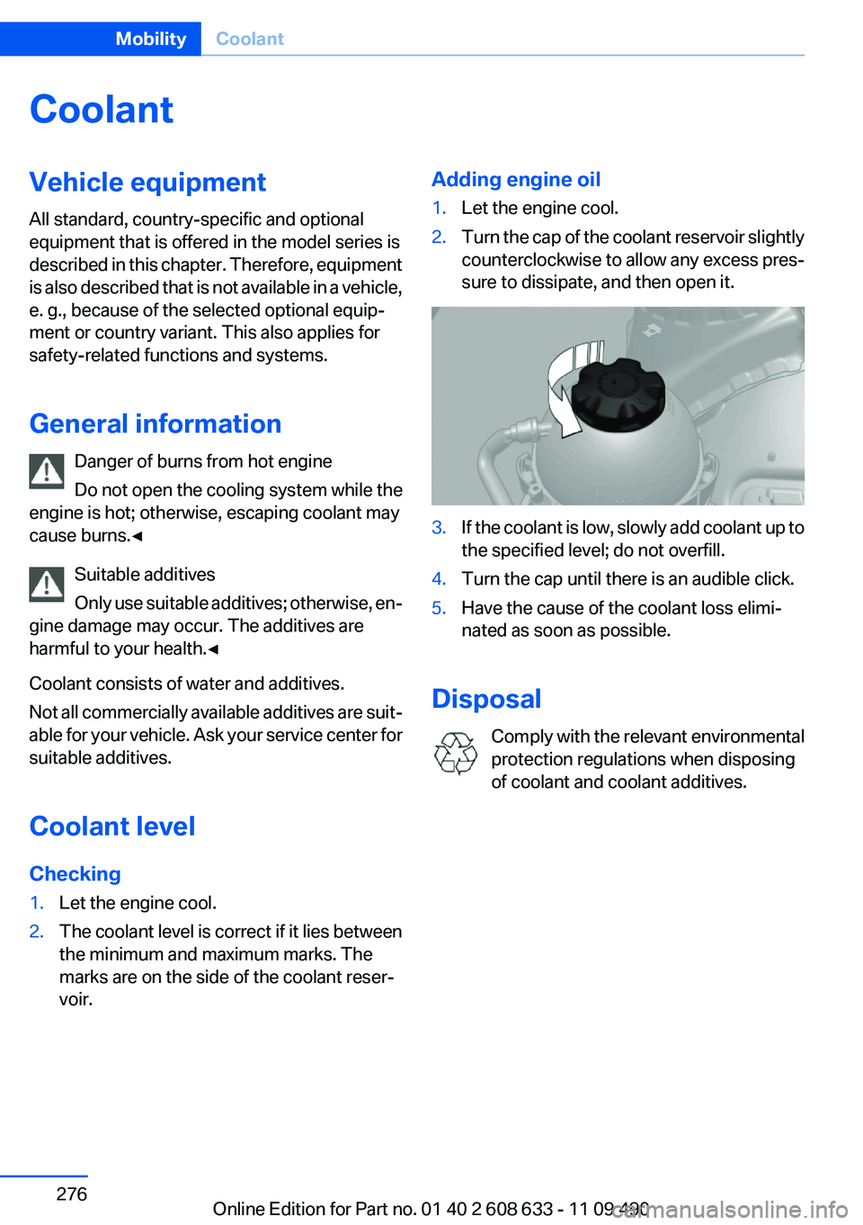
voir.Adding engine oil1.Let the engine cool.2.Turn the cap of the coolant reservoir slightly
counterclockwise to allow any excess pres‐
sure to dissipate, and then open it.3.If the coolant is low, slowly add coolant up to
the specified level; do not overfill.4.Turn the cap until there is an audible click.5.Have the cause of the coolant loss elimi‐
nated as soon as possible.
Disposal
Comply with the relevant environmental
protection regulations when disposing
of coolant and coolant additives.
Seite 276MobilityCoolant276
Online Edition for Part no. 01 40 2 608 633 - 11 09 490
Page 278 of 325
Socket for OBD Onboard
Diagnosis
Position
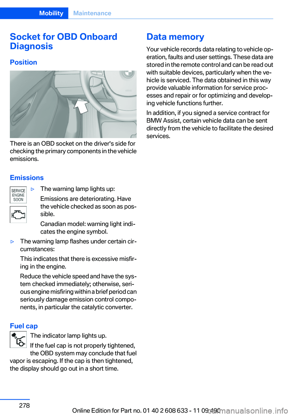
There is an OBD socket on the driver's side for
checking the primary components in the vehicle
emissions.
Emissions
▷The warning lamp lights up:
Emissions are deteriorating. Have
the vehicle checked as soon as pos‐
sible.
Canadian model: warning light indi‐
cates the engine symbol.▷The warning lamp flashes under certain cir‐
cumstances:
This indicates that there is excessive misfir‐
ing in the engine.
Reduce the vehicle speed and have the sys‐
tem checked immediately; otherwise, seri‐
ous engine misfiring within a brief period can
seriously damage emission control compo‐
nents, in particular the catalytic converter.
Fuel cap
The indicator lamp lights up.
If the fuel cap is not properly tightened,
the OBD system may conclude that fuel
vapor is escaping. If the cap is then tightened,
the display should go out in a short time.
Data memory
Your vehicle records data relating to vehicle op‐
eration, faults and user settings. These data are
stored in the remote control and can be read out
with suitable devices, particularly when the ve‐
hicle is serviced. The data obtained in this way
provide valuable information for service proc‐
esses and repair or for optimizing and develop‐
ing vehicle functions further.
In addition, if you signed a service contract for
BMW Assist, certain vehicle data can be sent
directly from the vehicle to facilitate the desired
services.Seite 278MobilityMaintenance278
Online Edition for Part no. 01 40 2 608 633 - 11 09 490
Page 293 of 325
3.Let both engines run for several minutes.4.Disconnect the jumper cables in the reverse
order.
Check the battery and recharge if necessary.
Tow-starting and towing
Automatic transmission: transporting
your vehicle
Note
Your vehicle is not permitted to be towed.
Therefore, contact a service center in the event
of a breakdown.
Do not have the vehicle towed
Have your vehicle transported on a loading
platform only; otherwise, damage may occur.◀
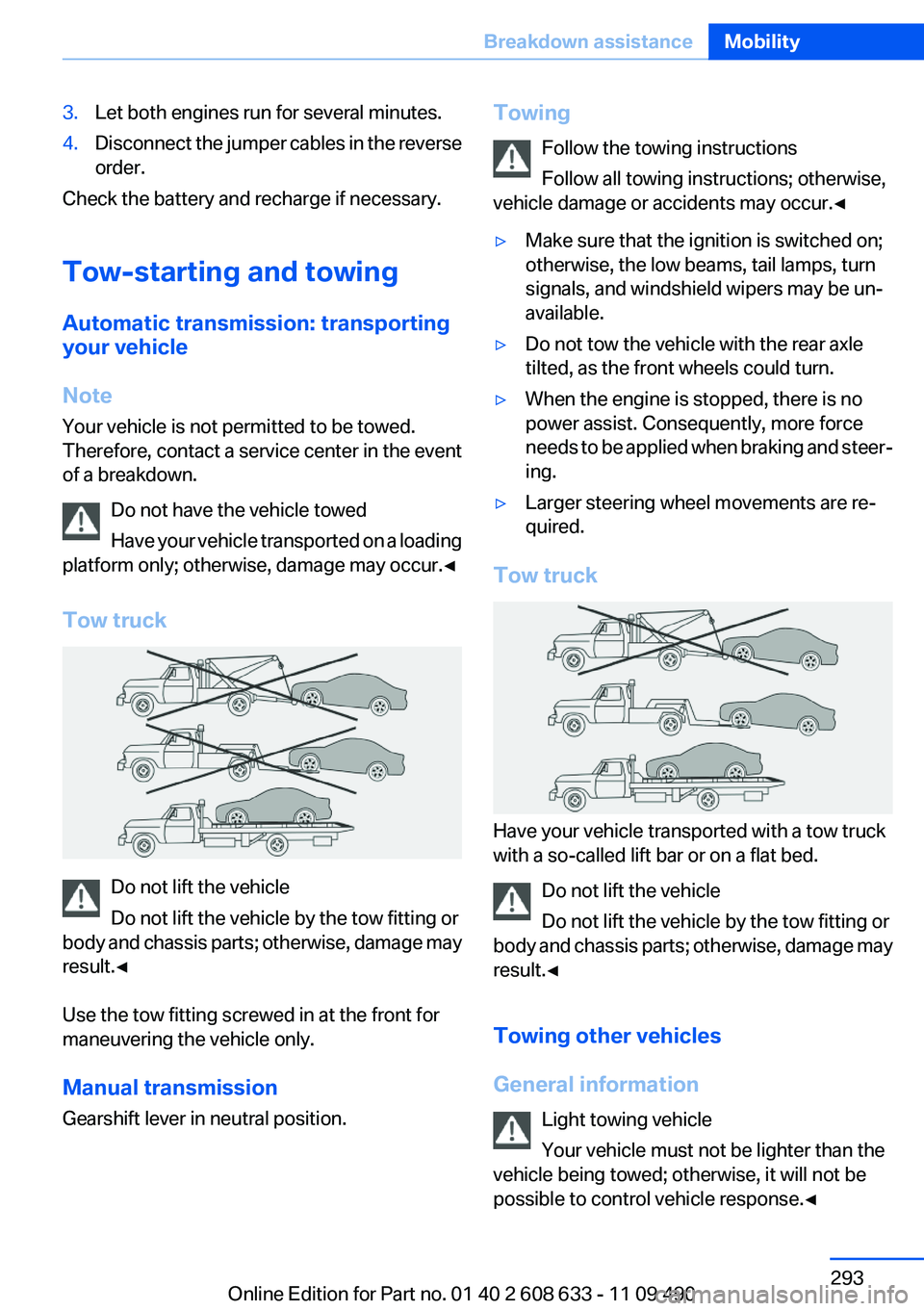
Tow truck
Do not lift the vehicle
Do not lift the vehicle by the tow fitting or
body and chassis parts; otherwise, damage may
result.◀
Use the tow fitting screwed in at the front for
maneuvering the vehicle only.
Manual transmission
Gearshift lever in neutral position.
Towing
Follow the towing instructions
Follow all towing instructions; otherwise,
vehicle damage or accidents may occur.◀▷Make sure that the ignition is switched on;
otherwise, the low beams, tail lamps, turn
signals, and windshield wipers may be un‐
available.▷Do not tow the vehicle with the rear axle
tilted, as the front wheels could turn.▷When the engine is stopped, there is no
power assist. Consequently, more force
needs to be applied when braking and steer‐
ing.▷Larger steering wheel movements are re‐
quired.
Tow truck
Have your vehicle transported with a tow truck
with a so-called lift bar or on a flat bed.
Do not lift the vehicle
Do not lift the vehicle by the tow fitting or
body and chassis parts; otherwise, damage may
result.◀
Towing other vehicles
General information Light towing vehicle
Your vehicle must not be lighter than the
vehicle being towed; otherwise, it will not be
possible to control vehicle response.◀
Seite 293Breakdown assistanceMobility293
Online Edition for Part no. 01 40 2 608 633 - 11 09 490