lock BMW 328I XDRIVE GRAN TURISMO 2015 Service Manual
[x] Cancel search | Manufacturer: BMW, Model Year: 2015, Model line: 328I XDRIVE GRAN TURISMO, Model: BMW 328I XDRIVE GRAN TURISMO 2015Pages: 251, PDF Size: 5.42 MB
Page 207 of 251
Hood
Hints Working in the engine compartment
Never attempt to perform any service or
repair operations on your vehicle without the
necessary professional technical training.
If you are unfamiliar with the statutory guide‐
lines, have any work on the vehicle performed
only by a service center.
If work is not carried out properly, there is a
danger of subsequent damage and related
safety hazards.◀
Never reach into the engine compart‐
ment
Never reach into spaces or gaps in the engine
compartment; otherwise, there is a risk of in‐
jury, e.g., from rotating or hot parts.◀
Fold down wiper arm
Before opening the hood, ensure that the
wiper arms are against the windshield, or this
may result in damage.◀
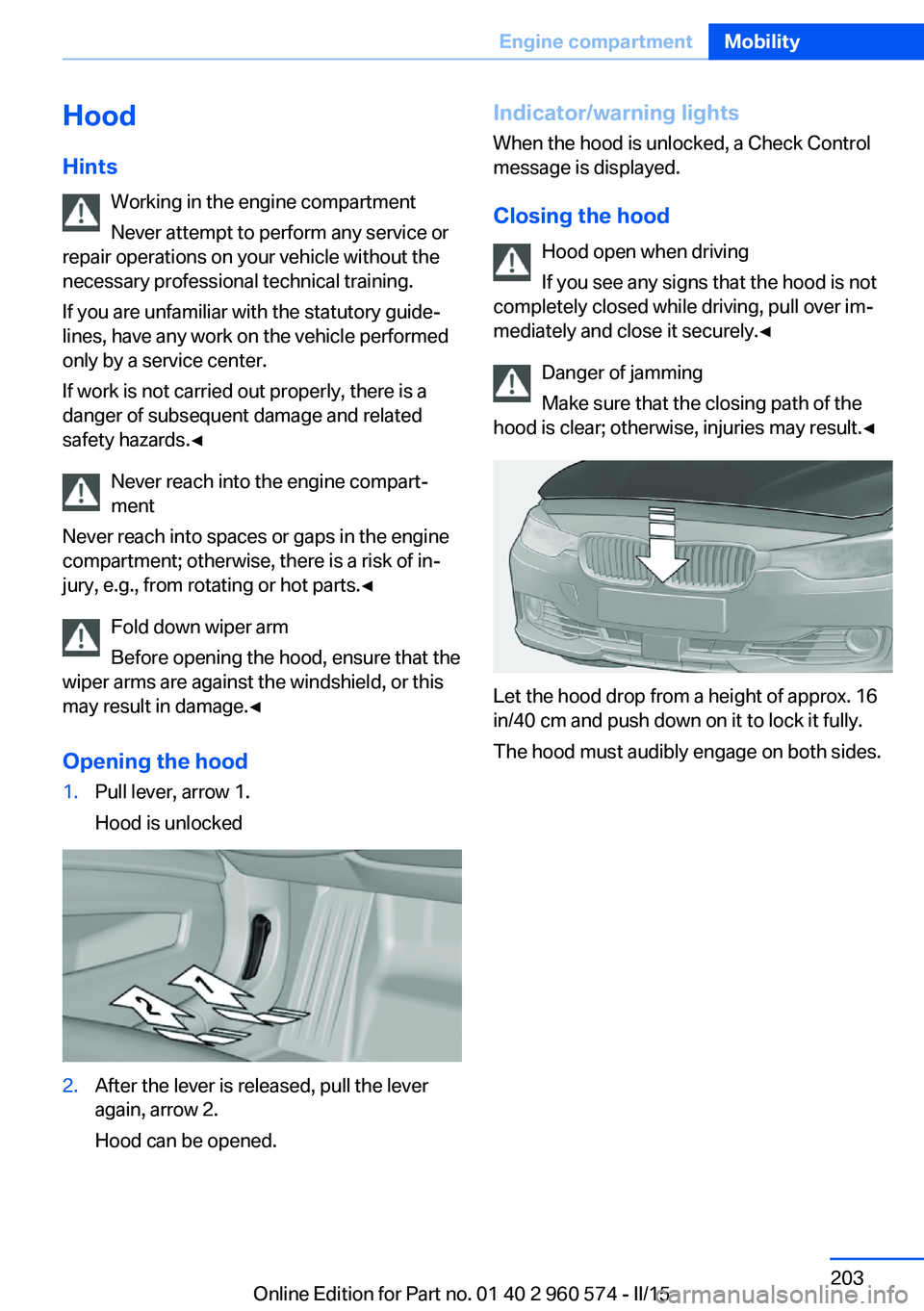
Opening the hood1.Pull lever, arrow 1.
Hood is unlocked2.After the lever is released, pull the lever
again, arrow 2.
Hood can be opened.Indicator/warning lights
When the hood is unlocked, a Check Control
message is displayed.
Closing the hood Hood open when driving
If you see any signs that the hood is not
completely closed while driving, pull over im‐
mediately and close it securely.◀
Danger of jamming
Make sure that the closing path of the
hood is clear; otherwise, injuries may result.◀
Let the hood drop from a height of approx. 16
in/40 cm and push down on it to lock it fully.
The hood must audibly engage on both sides.
Seite 203Engine compartmentMobility203
Online Edition for Part no. 01 40 2 960 574 - II/15
Page 211 of 251
CoolantVehicle features and optionsThis chapter describes all standard, country-
specific and optional features offered with the
series. It also describes features that are not
necessarily available in your car, e. g., due to
the selected options or country versions. This
also applies to safety-related functions and
systems. The respectively applicable country
provisions must be observed when using the
respective features and systems.
Hints Danger of burns from hot engine
Do not open the cooling system while
the engine is hot; otherwise, esliding coolant
may cause burns.◀
Suitable additives
Only use suitable additives; otherwise,
engine damage may occur. The additives are
harmful to your health.◀
Coolant consists of water and additives.
Not all commercially available additives are
suitable for the vehicle. Information about the
suitable additives are available from the service
center.
Coolant level
General information
Depending on the engine installation, the cool‐
ant reservoir is located on the right side or the
left side of the engine compartment.
Checking1.Let the engine cool.2.The coolant level is correct if it lies be‐
tween the minimum and maximum marks.The marks are on the side of the coolant
reservoir.SymbolMeaningMaximumMinimum
Adding
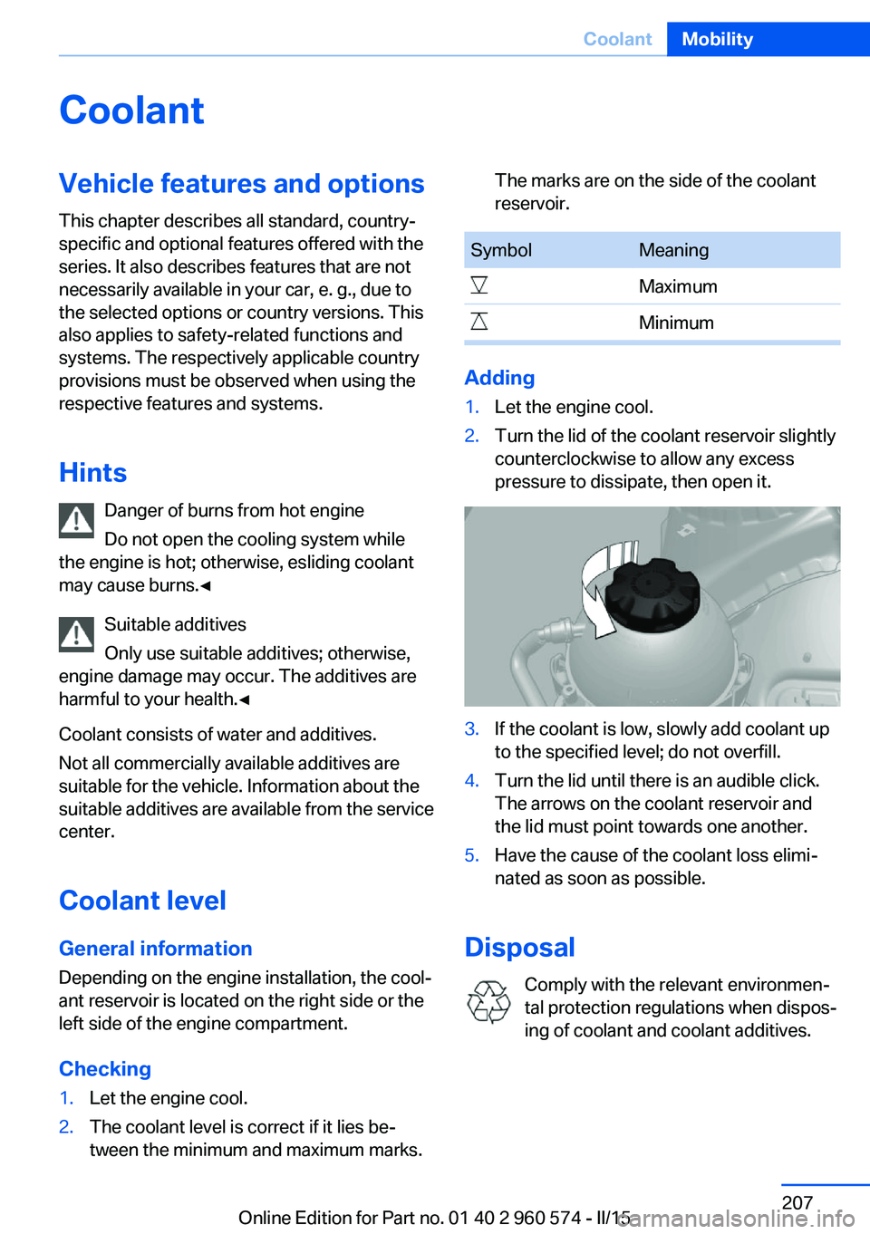
1.Let the engine cool.2.Turn the lid of the coolant reservoir slightly
counterclockwise to allow any excess
pressure to dissipate, then open it.3.If the coolant is low, slowly add coolant up
to the specified level; do not overfill.4.Turn the lid until there is an audible click.
The arrows on the coolant reservoir and
the lid must point towards one another.5.Have the cause of the coolant loss elimi‐
nated as soon as possible.
Disposal
Comply with the relevant environmen‐
tal protection regulations when dispos‐
ing of coolant and coolant additives.
Seite 207CoolantMobility207
Online Edition for Part no. 01 40 2 960 574 - II/15
Page 214 of 251
Replacing componentsVehicle features and optionsThis chapter describes all standard, country-
specific and optional features offered with the
series. It also describes features that are not
necessarily available in your car, e. g., due to
the selected options or country versions. This
also applies to safety-related functions and
systems. The respectively applicable country
provisions must be observed when using the
respective features and systems.
Onboard vehicle tool kit
The onboard vehicle tool kit is located behind
the left folding cover in the trunk.
Wiper blade replacement Note Do not fold down the wipers without
wiper blades
Do not fold down the wipers if wiper blades
have not been installed; this may damage the
windshield.◀
Replacing the wiper blades
1.To change the wiper blades, fold up, refer
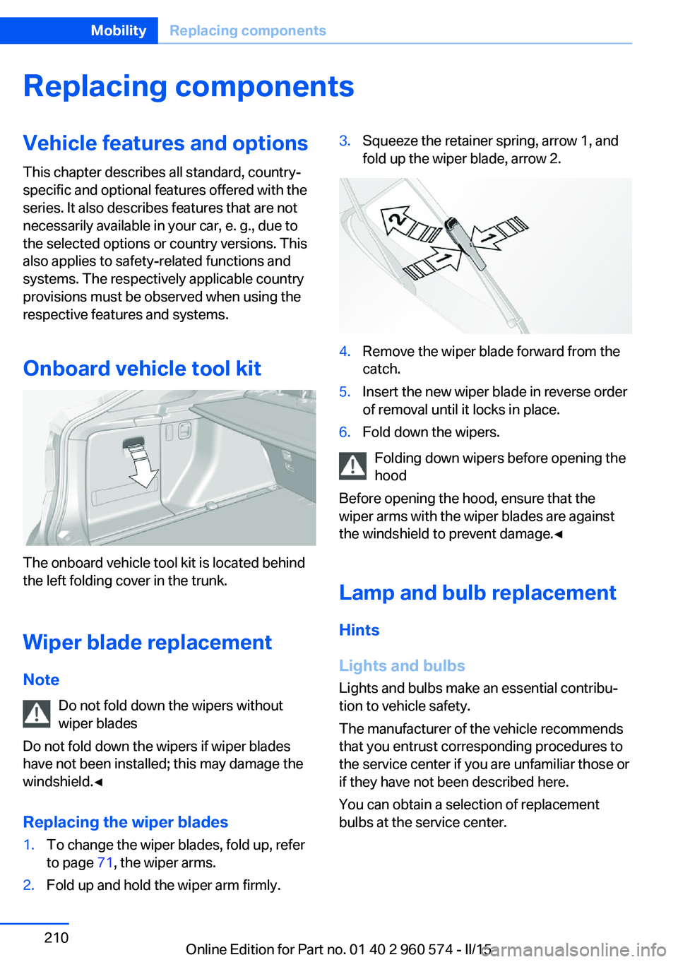
to page 71, the wiper arms.2.Fold up and hold the wiper arm firmly.3.Squeeze the retainer spring, arrow 1, and
fold up the wiper blade, arrow 2.4.Remove the wiper blade forward from the
catch.5.Insert the new wiper blade in reverse order
of removal until it locks in place.6.Fold down the wipers.
Folding down wipers before opening the hood
Before opening the hood, ensure that the
wiper arms with the wiper blades are against
the windshield to prevent damage.◀
Lamp and bulb replacement
Hints
Lights and bulbs Lights and bulbs make an essential contribu‐
tion to vehicle safety.
The manufacturer of the vehicle recommends
that you entrust corresponding procedures to
the service center if you are unfamiliar those or
if they have not been described here.
You can obtain a selection of replacement
bulbs at the service center.
Seite 210MobilityReplacing components210
Online Edition for Part no. 01 40 2 960 574 - II/15
Page 216 of 251
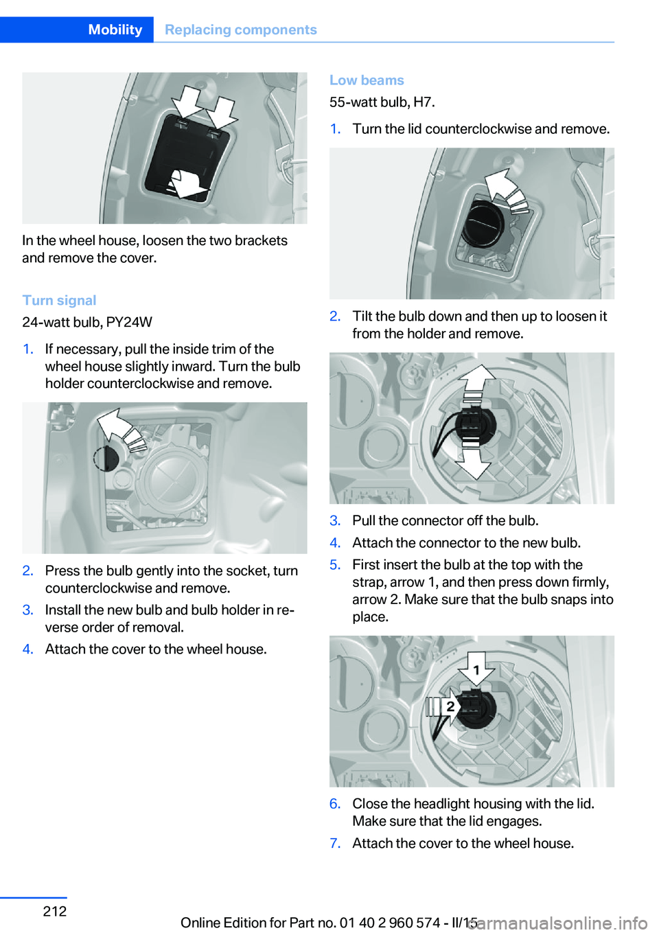
In the wheel house, loosen the two brackets
and remove the cover.
Turn signal
24-watt bulb, PY24W
1.If necessary, pull the inside trim of the
wheel house slightly inward. Turn the bulb
holder counterclockwise and remove.2.Press the bulb gently into the socket, turn
counterclockwise and remove.3.Install the new bulb and bulb holder in re‐
verse order of removal.4.Attach the cover to the wheel house.Low beams
55-watt bulb, H7.1.Turn the lid counterclockwise and remove.2.Tilt the bulb down and then up to loosen it
from the holder and remove.3.Pull the connector off the bulb.4.Attach the connector to the new bulb.5.First insert the bulb at the top with the
strap, arrow 1, and then press down firmly,
arrow 2. Make sure that the bulb snaps into
place.6.Close the headlight housing with the lid.
Make sure that the lid engages.7.Attach the cover to the wheel house.Seite 212MobilityReplacing components212
Online Edition for Part no. 01 40 2 960 574 - II/15
Page 217 of 251
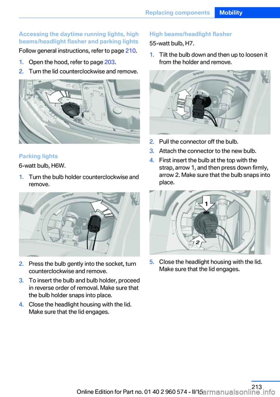
Accessing the daytime running lights, high
beams/headlight flasher and parking lights
Follow general instructions, refer to page 210.1.Open the hood, refer to page 203.2.Turn the lid counterclockwise and remove.
Parking lights
6-watt bulb, H6W.
1.Turn the bulb holder counterclockwise and
remove.2.Press the bulb gently into the socket, turn
counterclockwise and remove.3.To insert the bulb and bulb holder, proceed
in reverse order of removal. Make sure that
the bulb holder snaps into place.4.Close the headlight housing with the lid.
Make sure that the lid engages.High beams/headlight flasher
55-watt bulb, H7.1.Tilt the bulb down and then up to loosen it
from the holder and remove.2.Pull the connector off the bulb.3.Attach the connector to the new bulb.4.First insert the bulb at the top with the
strap, arrow 1, and then press down firmly,
arrow 2. Make sure that the bulb snaps into
place.5.Close the headlight housing with the lid.
Make sure that the lid engages.Seite 213Replacing componentsMobility213
Online Edition for Part no. 01 40 2 960 574 - II/15
Page 219 of 251
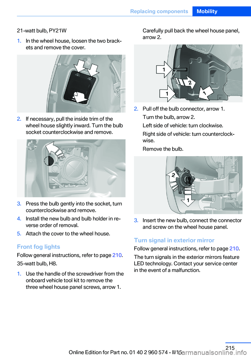
21-watt bulb, PY21W1.In the wheel house, loosen the two brack‐
ets and remove the cover.2.If necessary, pull the inside trim of the
wheel house slightly inward. Turn the bulb
socket counterclockwise and remove.3.Press the bulb gently into the socket, turn
counterclockwise and remove.4.Install the new bulb and bulb holder in re‐
verse order of removal.5.Attach the cover to the wheel house.
Front fog lights
Follow general instructions, refer to page 210.
35-watt bulb, H8.
1.Use the handle of the screwdriver from the
onboard vehicle tool kit to remove the
three wheel house panel screws, arrow 1.Carefully pull back the wheel house panel,
arrow 2.2.Pull off the bulb connector, arrow 1.
Turn the bulb, arrow 2.
Left side of vehicle: turn clockwise.
Right side of vehicle: turn counterclock‐
wise.
Remove the bulb.3.Insert the new bulb, connect the connector
and screw on the wheel house panel.
Turn signal in exterior mirror
Follow general instructions, refer to page 210.
The turn signals in the exterior mirrors feature
LED technology. Contact your service center
in the event of a malfunction.
Seite 215Replacing componentsMobility215
Online Edition for Part no. 01 40 2 960 574 - II/15
Page 221 of 251
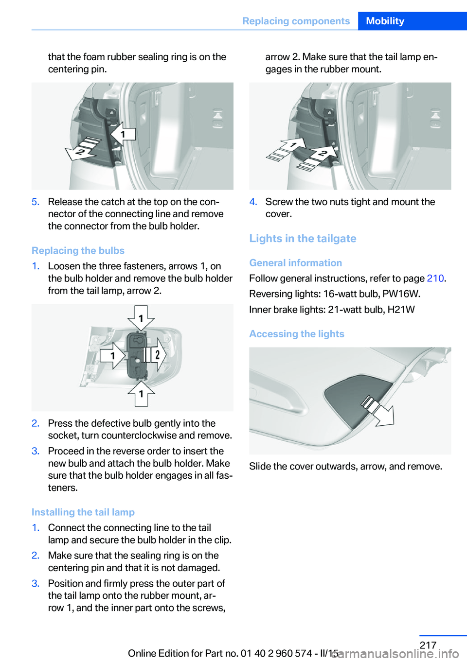
that the foam rubber sealing ring is on the
centering pin.5.Release the catch at the top on the con‐
nector of the connecting line and remove
the connector from the bulb holder.
Replacing the bulbs
1.Loosen the three fasteners, arrows 1, on
the bulb holder and remove the bulb holder
from the tail lamp, arrow 2.2.Press the defective bulb gently into the
socket, turn counterclockwise and remove.3.Proceed in the reverse order to insert the
new bulb and attach the bulb holder. Make
sure that the bulb holder engages in all fas‐
teners.
Installing the tail lamp
1.Connect the connecting line to the tail
lamp and secure the bulb holder in the clip.2.Make sure that the sealing ring is on the
centering pin and that it is not damaged.3.Position and firmly press the outer part of
the tail lamp onto the rubber mount, ar‐
row 1, and the inner part onto the screws,arrow 2. Make sure that the tail lamp en‐
gages in the rubber mount.4.Screw the two nuts tight and mount the
cover.
Lights in the tailgate
General information
Follow general instructions, refer to page 210.
Reversing lights: 16-watt bulb, PW16W.
Inner brake lights: 21-watt bulb, H21W
Accessing the lights
Slide the cover outwards, arrow, and remove.
Seite 217Replacing componentsMobility217
Online Edition for Part no. 01 40 2 960 574 - II/15
Page 222 of 251
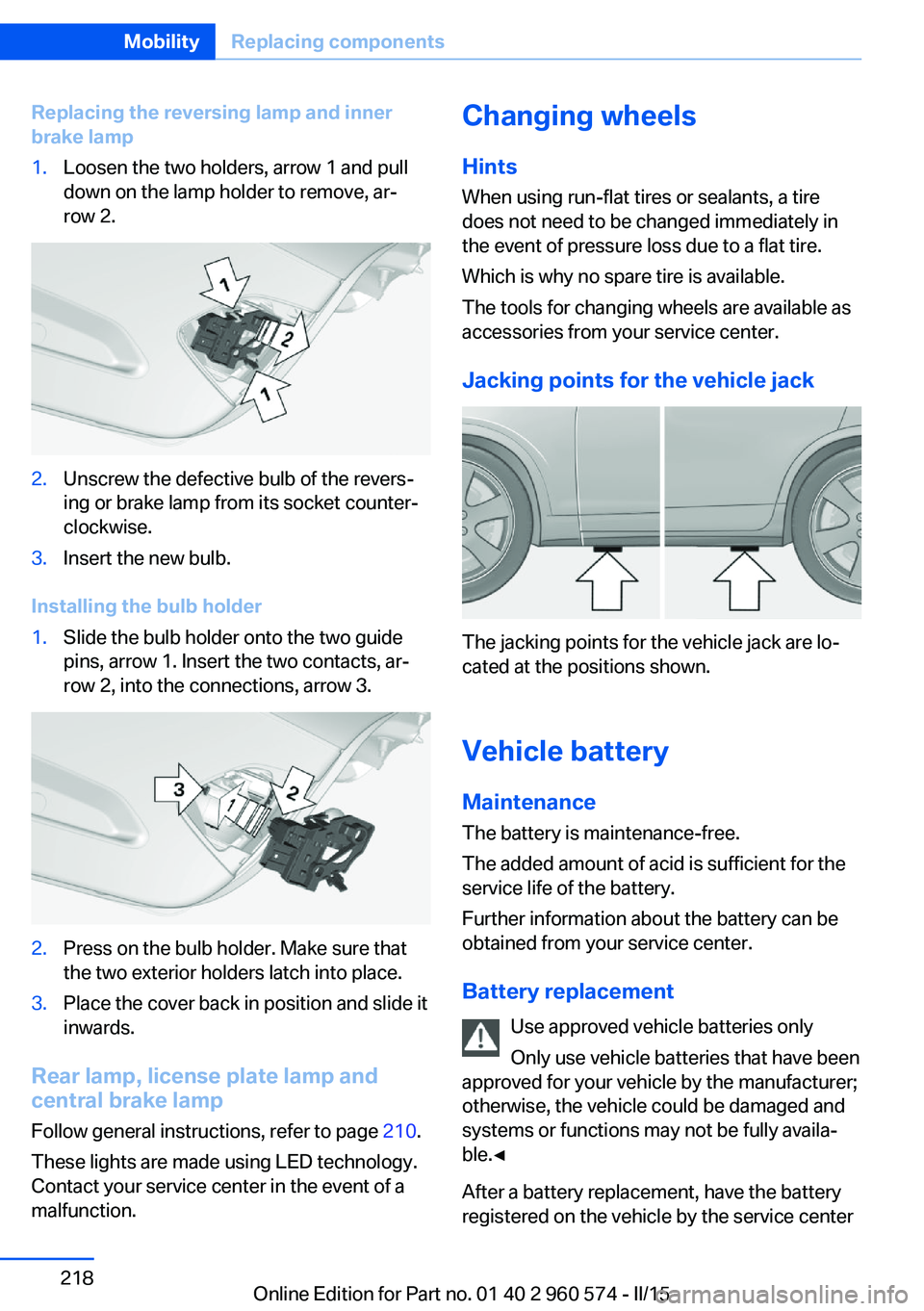
Replacing the reversing lamp and inner
brake lamp1.Loosen the two holders, arrow 1 and pull
down on the lamp holder to remove, ar‐
row 2.2.Unscrew the defective bulb of the revers‐
ing or brake lamp from its socket counter‐
clockwise.3.Insert the new bulb.
Installing the bulb holder
1.Slide the bulb holder onto the two guide
pins, arrow 1. Insert the two contacts, ar‐
row 2, into the connections, arrow 3.2.Press on the bulb holder. Make sure that
the two exterior holders latch into place.3.Place the cover back in position and slide it
inwards.
Rear lamp, license plate lamp and
central brake lamp
Follow general instructions, refer to page 210.
These lights are made using LED technology.
Contact your service center in the event of a
malfunction.
Changing wheels
Hints
When using run-flat tires or sealants, a tire
does not need to be changed immediately in
the event of pressure loss due to a flat tire.
Which is why no spare tire is available.
The tools for changing wheels are available as
accessories from your service center.
Jacking points for the vehicle jack
The jacking points for the vehicle jack are lo‐
cated at the positions shown.
Vehicle battery Maintenance
The battery is maintenance-free.
The added amount of acid is sufficient for the
service life of the battery.
Further information about the battery can be
obtained from your service center.
Battery replacement Use approved vehicle batteries only
Only use vehicle batteries that have been
approved for your vehicle by the manufacturer;
otherwise, the vehicle could be damaged and
systems or functions may not be fully availa‐
ble.◀
After a battery replacement, have the battery
registered on the vehicle by the service center
Seite 218MobilityReplacing components218
Online Edition for Part no. 01 40 2 960 574 - II/15
Page 231 of 251
Before driving into a car wash
In order to ensure that the vehicle can roll in a
car wash, take the following steps:
Steptronic transmission:1.Drive into the car wash.2.Engage selector lever position N.3.Switch the engine off.
In this way, the ignition remains switched
on, and a Check-Control message is dis‐
played.
Do not turn off the ignition in the car
wash
Do not turn off the ignition in the car wash;
otherwise, selector lever position P is en‐
gaged and damages can result.◀
The vehicle cannot be locked from the outside
when in selector lever position N. A signal
sounds when an attempt is made to lock the
vehicle.
To start the engine with Steptronic transmis‐
sion:
1.Depress the brake pedal.2.Press the Start/Stop button.
Pressing the Start/Stop button without step‐
ping on the brake turns the ignition off.
Selector lever positionSelector lever position P is engaged automati‐
cally:
▷When the ignition is switched off.▷After approx. 15 minutes.
Headlights
▷Do not rub dry and do not use abrasive or
acidic cleansers.▷Soak areas that have been dirtied e. g.,
from insects, with shampoo and wash off
with water.▷Thaw ice with de-icing spray; do not use an
ice scraper.After washing the vehicle
After washing the vehicle, apply the brakes
briefly to dry them; otherwise, braking action
can be reduced and corrosion of the brake
discs can occur.
Completely remove all residues on the win‐
dows, to minimize loss of visibility due to
smearing and to reduce wiper noises and
wiper blade wear.
Vehicle care
Car care products BMW recommends using care and cleaning
products from BMW, since these have been
tested and approved.
Car care and cleaning products
Follow the instructions on the container.
When cleaning the interior, open the doors or
windows.
Only use products intended for cleaning vehi‐
cles.
Cleansers can contain substances that are
dangerous and harmful to your health.◀
Vehicle paint
Regular care contributes to driving safety and
value retention. Environmental influences in
areas with elevated air pollution or natural con‐
taminants, such as tree resin or pollen can af‐
fect the vehicle's paintwork. Tailor the fre‐
quency and extent of your car care to these
influences.
Aggressive substances such as spilled fuel, oil,
grease or bird droppings, must be removed im‐
mediately to prevent the finish from being al‐
tered or discolored.
Leather care
Remove dust from the leather often, using a
cloth or vacuum cleaner.Seite 227CareMobility227
Online Edition for Part no. 01 40 2 960 574 - II/15
Page 240 of 251
Everything from A to Z
IndexA ABS, Antilock Brake Sys‐ tem 119
ACC, Active Cruise Control with Stop & Go 126
Acceleration Assistant, refer to Launch Control 75
Accessories and parts 7
Activated-charcoal filter 152
Active Blind Spot Detec‐ tion 116
Active Cruise Control with Stop & Go, ACC 126
Active rear spoiler 121
Adaptive brake lights, refer to Brake force display 118
Adaptive Light Control 93
Additives, oil 205
Adjustments, seats/head re‐ straints 51
After washing vehicle 227
Airbags 97
Airbags, indicator/warning light 98
Air circulation, refer to Recir‐ culated-air mode 148, 151
Air, dehumidifying, refer to Cooling function 148, 151
Air distribution, manual 148, 151
Air flow, air conditioner 148
Air flow, automatic climate control 151
Air pressure, tires 190
Air vents, refer to Ventila‐ tion 152
Alarm system 46
Alarm, unintentional 47
All around the center con‐ sole 16 All around the roofliner 17
All around the steering wheel 14
All-season tires, refer to Win‐ ter tires 197
All-wheel-drive 120
Alternating-code hand-held transmitter 155
Alternative oil types 206
Ambient light 96
Antifreeze, washer fluid 72
Antilock Brake System, ABS 119
Anti-slip control, refer to DSC 119
Approved axle load 233
Approved engine oils, see Suitable engine oil
types 206
Arrival time 87
Ash tray 158
Assistance when driving off 124
Assist system information, on Control Display 90
Attentiveness assistant 118
AUTO intensity 150
Automatic car wash 226
Automatic climate con‐ trol 147
Automatic climate control with enhanced features 149
Automatic Cruise Control with Stop & Go 126
Automatic Curb Monitor 58
Automatic deactivation, front- seat passenger airbags 99
Automatic headlight con‐ trol 93
Automatic locking 45 Automatic recirculated-air
control 151
Automatic tailgate 40
Automatic transmission, see Steptronic transmission 72
AUTO program, automatic cli‐ mate control 150
AUTO program, climate con‐ trol 148
AUTO program, intensity 150
Auto Start/Stop function 67
Average fuel consumption 87
Average speed 87
Axle loads, weights 233
B Backrest curvature, refer to Lumbar support 53
Backrest, width 53
Band-aids, refer to First aid kit 222
Bar for tow-starting/ towing 224
Battery replacement, vehicle battery 218
Battery replacement, vehicle remote control 35
Battery, vehicle 218
Belts, safety belts 54
Beverage holder, cu‐ pholder 165
BMW Assist, see user's manual for Navigation, En‐
tertainment and Communi‐
cation
BMW Driver’s Guide App 6
BMW Homepage 6
BMW Internet page 6
BMW maintenance sys‐ tem 208 Seite 236ReferenceEverything from A to Z236
Online Edition for Part no. 01 40 2 960 574 - II/15