belt BMW 335I SEDAN 2015 User Guide
[x] Cancel search | Manufacturer: BMW, Model Year: 2015, Model line: 335I SEDAN, Model: BMW 335I SEDAN 2015Pages: 257, PDF Size: 5.55 MB
Page 70 of 257
Engine stop
Hints Take the remote control with youTake the remote control with you when
leaving the vehicle so that children, e.g., can‐
not start the engine.◀
Apply parking brake and further secure
the vehicle if needed.
Set the parking brake firmly when parking; oth‐
erwise, the vehicle could roll. On steep upward
and downward inclines, further secure the ve‐
hicle, e.g., by turning the steering wheel in the
direction of the curb.◀
Before driving into a car wash So that the vehicle can roll into a car wash ob‐
serve instructions for going into an automatic
car wash, refer to page 229.
Steptronic transmission
Switching off the engine1.Engage selector lever position P with the
vehicle stopped.2.Press the Start/Stop button.
The engine is switched off.
The radio-ready state is switched on.3.Set the parking brake.
Manual transmission
Switching off the engine
1.With the vehicle at a standstill, press the
Start/Stop button.2.Shift into first gear or reverse.3.Set the parking brake.Auto Start/Stop function
The concept The Auto Start/Stop function helps save fuel.
The system switches off the engine during a
stop, e.g., in traffic congestion or at traffic lights. The ignition remains switched on. The
engine starts again automatically for driving
off.
Automatic mode After every start of the engine using the Start/
Stop button, the Auto Start/Stop function is in
the last selected state, refer to page 68.
When the Auto Start/Stop function is active, it
is available when the vehicle is traveling faster
than about 3 mph, approx. 5 km/h.
Engine stop
The engine is switched off automatically dur‐
ing a stop under the following conditions:
Steptronic transmission:▷The selector lever is in selector lever posi‐
tion D.▷Brake pedal remains depressed while the
vehicle is stopped.▷The driver's safety belt is buckled or the
driver's door is closed.
Manual transmission:
▷Neutral is engaged and the clutch pedal is
not pressed.▷The driver's safety belt is buckled or the
driver's door is closed.
The air flow from the air conditioner is reduced
when the engine is switched off.
Displays in the instrument cluster The READY display in the tach‐
ometer signals that the Auto
Start/Stop function is ready to
start the engine automatically.
Seite 66ControlsDriving66
Online Edition for Part no. 01 40 2 960 440 - II/15
Page 71 of 257
The display indicates that the
conditions for an automatic en‐
gine stop have not been met.
Functional limitations
The engine is not switched off automatically in
the following situations:▷External temperature too low.▷The external temperature is high and auto‐
matic climate control is running.▷The car's interior has not yet been heated
or cooled to the required level.▷The engine is not yet at operating temper‐
ature.▷The wheels are at a sharp angle or the
steering wheel is being turned.▷After driving in reverse.▷Fogging of the windows when the auto‐
matic climate control is switched on.▷Vehicle battery is heavily discharged.▷At higher elevations.▷The engine compartment lid is unlocked.▷The parking assistant is activated.▷Stop-and-go traffic.▷The selector lever is in position N, M/S or
R.▷Use of fuel with high ethanol content.
Starting the engine
The engine starts automatically under the fol‐
lowing conditions:
▷Steptronic transmission:
By releasing the brake pedal.▷Manual transmission:
The clutch pedal is pressed.
After the engine starts, accelerate as usual.
Safety mode
After the engine switches off automatically, it
will not start again automatically if any one of
the following conditions are met.▷The driver's safety belt is unbuckled and
the driver's door is open.▷The hood was unlocked.
Some indicator lights light up for a varied
length of time.
The engine can only be started via the Start/
Stop button.
Functional limitations
Even if driving off was not intended, the deacti‐
vated engine starts up automatically in the fol‐
lowing situations:
▷Excessive warming of the car's interior
when the cooling function is switched on.▷The steering wheel is turned.▷Steptronic transmission: change from se‐
lector lever position D to R, N or M/S.▷Steptronic transmission: change from se‐
lector lever position P to N, D, R or M/S.▷The vehicle begins rolling.▷Fogging of the windows when the auto‐
matic climate control is switched on.▷Vehicle battery is heavily discharged.▷Excessive cooling of the car's interior when
the heating is switched on.▷Low brake vacuum pressure; this can oc‐
cur, e.g., if the brake pedal is depressed a
number of times in succession.Seite 67DrivingControls67
Online Edition for Part no. 01 40 2 960 440 - II/15
Page 77 of 257
off, refer to page 64, and when selector
lever position R or D is set.▷With the ignition off, if selector lever posi‐
tion N is set.▷If the driver's safety belt is released, the
driver's door is opened, and the brake
pedal is not pressed while the vehicle is
stationary and selector lever position D or
R is set.
Before exiting the vehicle, make sure that se‐
lector lever position P is set. Otherwise, the ve‐
hicle may begin to move.
Kickdown Kickdown is used to achieve maximum driving
performance. Step on the accelerator pedal
beyond the resistance point at the full throttle
position.
Engaging selector lever positions Press on the brake pedal until you start
driving
To prevent the vehicle from creeping after you
select a gear, maintain pressure on the brake
pedal until you are ready to start.◀
▷It is not possible to shift out of selector
lever position P until the engine is running
and the brake is applied.▷With the vehicle is stationary, press on the
brake pedal before shifting out of P or N;
otherwise, the shift command will not be
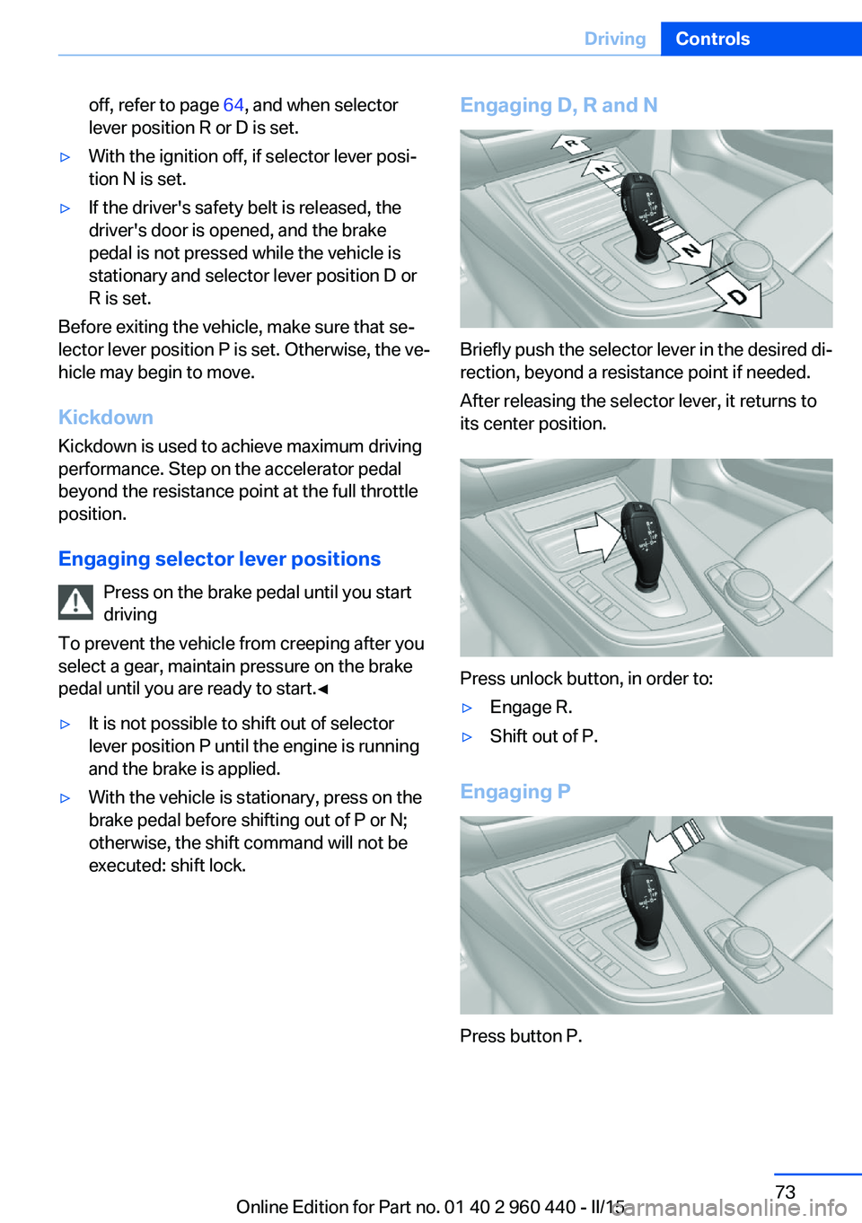
executed: shift lock.Engaging D, R and N
Briefly push the selector lever in the desired di‐
rection, beyond a resistance point if needed.
After releasing the selector lever, it returns to
its center position.
Press unlock button, in order to:
▷Engage R.▷Shift out of P.
Engaging P
Press button P.
Seite 73DrivingControls73
Online Edition for Part no. 01 40 2 960 440 - II/15
Page 82 of 257
▷Messages, e.g. Check Control, refer to
page 78.▷Current fuel consumption, refer to
page 83.▷Navigation display, see User's manual for
Navigation, Entertainment and Communi‐
cation.▷Range, refer to page 82.▷Status, Driving Dynamics Control, refer to
page 121.▷Service requirements, refer to page 83.▷Speed limit detection, refer to page 85.▷Time, refer to page 82.
Check Control
The concept The Check Control system monitors functions
in the vehicle and notifies you of malfunctions
in the monitored systems.
A Check Control message is displayed as a
combination of indicator or warning lights and
text messages in the instrument cluster and in
the Head-up Display.
In addition, an acoustic signal may sound and a text message may appear on the Control Dis‐
play.
Indicator/warning lights
General information
The indicator and warning lights in the instru‐
ment cluster can light up in a variety of combi‐
nations and colors.
Several of the lights are checked for proper
functioning and light up temporarily when the
engine is started or the ignition is switched on.
Red lights
Safety belt reminder Flashing or illuminated: safety belt on
the driver or passenger side is not
buckled. The safety belt reminder can
also be activated if objects are placed on the
front passenger seat.
Make sure that the safety belts are positioned
correctly.
Airbag system Airbag system and belt tensioner are
defective.
Have the vehicle checked by the serv‐
ice center immediately.
Parking brake, brake system For additional information, refer to Re‐
lease parking brake, refer to page 68.
Front-end collision warning Illuminated: advance warning is issued,
e.g., when there is the impending dan‐
ger of a collision or the distance to the
vehicle ahead is too small.
Increase distance.
Flashing: acute warning of the imminent dan‐
ger of a collision when the vehicle approaches
another vehicle at a relatively high differential
speed.
Intervention by braking or make an evasive ma‐
neuver.
Pedestrian warning Symbol in the instrument cluster.Seite 78ControlsDisplays78
Online Edition for Part no. 01 40 2 960 440 - II/15
Page 101 of 257
SafetyVehicle features and options
This chapter describes all standard, country-
specific and optional features offered with the
series. It also describes features that are not
necessarily available in your car, e. g., due tothe selected options or country versions. This
also applies to safety-related functions and
systems. The respectively applicable country
provisions must be observed when using the
respective features and systems.
Airbags
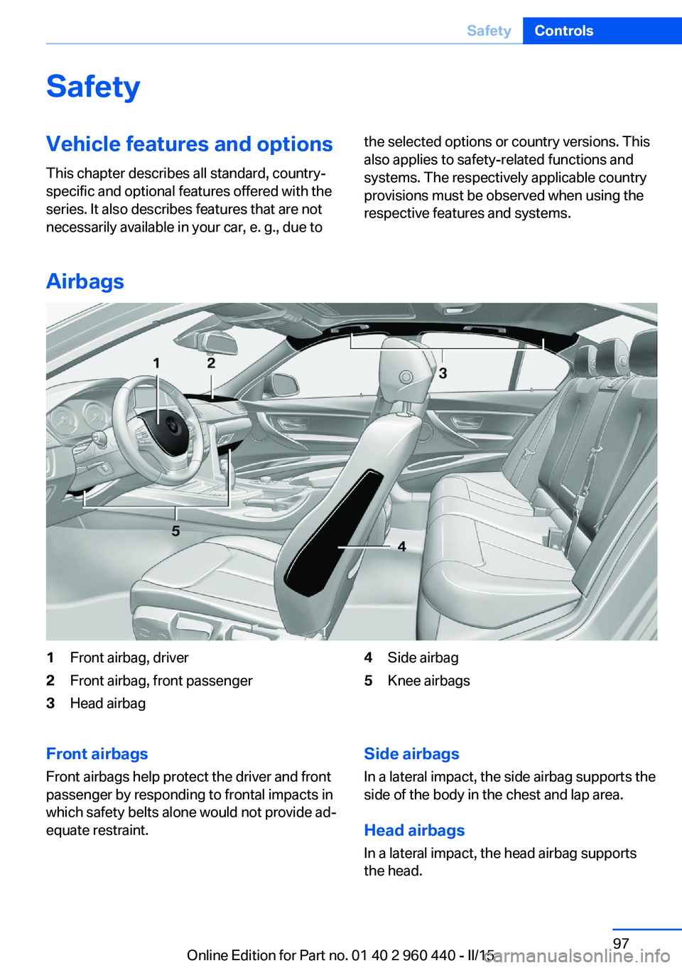
1Front airbag, driver2Front airbag, front passenger3Head airbag4Side airbag5Knee airbagsFront airbags
Front airbags help protect the driver and front
passenger by responding to frontal impacts in
which safety belts alone would not provide ad‐
equate restraint.Side airbags
In a lateral impact, the side airbag supports the
side of the body in the chest and lap area.
Head airbags
In a lateral impact, the head airbag supports
the head.Seite 97SafetyControls97
Online Edition for Part no. 01 40 2 960 440 - II/15
Page 103 of 257
erational readiness of the entire airbag system
and the belt tensioner.
Airbag system malfunctioning▷Warning lamp does not come on when the
ignition is turned on.▷The warning lamp lights up continuously.
In case of a malfunction have airbag sys‐
tem checked immediately.
In case of a malfunction have airbag system
checked immediately; otherwise, there is a risk
that the system does not function as expected
in case of a severe accident.◀
Automatic deactivation of the front-
seat passenger airbags
The system reads if the front passenger seat is
occupied by measuring the human body's re‐
sistance.
Front, knee and side airbag on the front pas‐
senger's side are either activated or deacti‐
vated.
Leave feet in the footwell
Make sure that the front passenger
keeps his or her feet in the footwell; otherwise,
proper functioning of the front passenger air‐
bag might not be assured.◀
Child restraint fixing system in the front
passenger seat
Before transporting a child on the front pas‐
senger seat, refer to the safety notes and in‐
structions for children on the front passenger
seat, see Children.◀
Malfunction of the automatic
deactivation system
When transporting older children and adults,
the front-seat passenger airbags may be deac‐
tivated in certain sitting positions. In this case,
the indicator lamp for the front-seat passenger
airbags lights up.
In this case, change the sitting position so that
the front-seat passenger airbags are activated
and the indicator lamp goes out.
If it is not possible to activate the airbags, have
the person sit in the rear.
To enable correct recognition of the occupied
seat cushion▷Do not attach covers, cushions, ball mats
or other items to the front passenger seat
unless they are specifically recommended
by your vehicle's manufacturer.▷Do not place any electronic devices on the
passenger seat if a child restraint system is
to be installed on it.▷Do not place objects under the seat that
could press against the seat from below.▷No moisture in or on the seat.
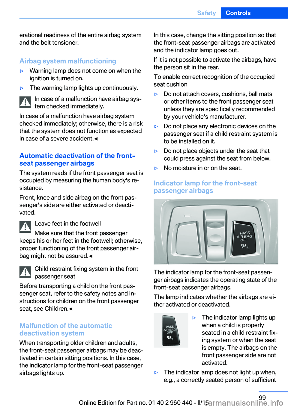
Indicator lamp for the front-seat
passenger airbags
The indicator lamp for the front-seat passen‐
ger airbags indicates the operating state of the
front-seat passenger airbags.
The lamp indicates whether the airbags are ei‐
ther activated or deactivated.
▷The indicator lamp lights up
when a child is properly
seated in a child restraint fix‐
ing system or when the seat
is empty. The airbags on the
front passenger side are not
activated.▷The indicator lamp does not light up when,
e.g., a correctly seated person of sufficientSeite 99SafetyControls99
Online Edition for Part no. 01 40 2 960 440 - II/15
Page 130 of 257
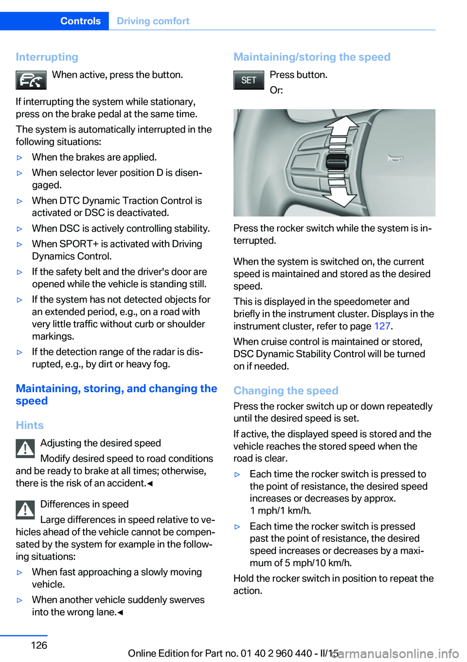
InterruptingWhen active, press the button.
If interrupting the system while stationary,
press on the brake pedal at the same time.
The system is automatically interrupted in the
following situations:▷When the brakes are applied.▷When selector lever position D is disen‐
gaged.▷When DTC Dynamic Traction Control is
activated or DSC is deactivated.▷When DSC is actively controlling stability.▷When SPORT+ is activated with Driving
Dynamics Control.▷If the safety belt and the driver's door are
opened while the vehicle is standing still.▷If the system has not detected objects for
an extended period, e.g., on a road with
very little traffic without curb or shoulder
markings.▷If the detection range of the radar is dis‐
rupted, e.g., by dirt or heavy fog.
Maintaining, storing, and changing the
speed
Hints Adjusting the desired speedModify desired speed to road conditions
and be ready to brake at all times; otherwise,
there is the risk of an accident.◀
Differences in speed
Large differences in speed relative to ve‐
hicles ahead of the vehicle cannot be compen‐
sated by the system for example in the follow‐
ing situations:
▷When fast approaching a slowly moving
vehicle.▷When another vehicle suddenly swerves
into the wrong lane.◀Maintaining/storing the speed
Press button.
Or:
Press the rocker switch while the system is in‐
terrupted.
When the system is switched on, the current
speed is maintained and stored as the desired
speed.
This is displayed in the speedometer and
briefly in the instrument cluster. Displays in the
instrument cluster, refer to page 127.
When cruise control is maintained or stored,
DSC Dynamic Stability Control will be turned
on if needed.
Changing the speed
Press the rocker switch up or down repeatedly
until the desired speed is set.
If active, the displayed speed is stored and the vehicle reaches the stored speed when the
road is clear.
▷Each time the rocker switch is pressed to
the point of resistance, the desired speed
increases or decreases by approx.
1 mph/1 km/h.▷Each time the rocker switch is pressed
past the point of resistance, the desired
speed increases or decreases by a maxi‐
mum of 5 mph/10 km/h.
Hold the rocker switch in position to repeat the
action.
Seite 126ControlsDriving comfort126
Online Edition for Part no. 01 40 2 960 440 - II/15
Page 162 of 257
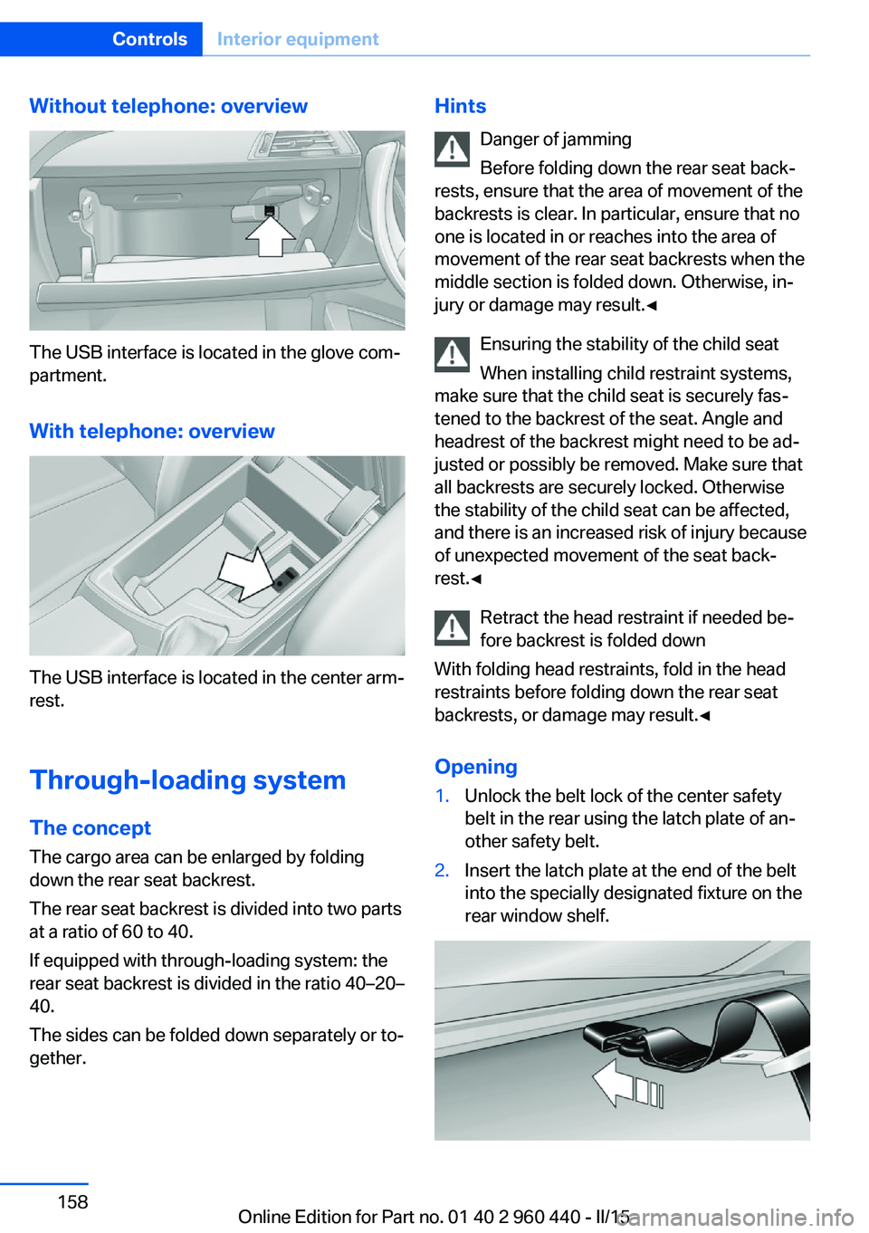
Without telephone: overview
The USB interface is located in the glove com‐
partment.
With telephone: overview
The USB interface is located in the center arm‐
rest.
Through-loading system The concept The cargo area can be enlarged by folding
down the rear seat backrest.
The rear seat backrest is divided into two parts at a ratio of 60 to 40.
If equipped with through-loading system: the
rear seat backrest is divided in the ratio 40–20–
40.
The sides can be folded down separately or to‐
gether.
Hints
Danger of jamming
Before folding down the rear seat back‐
rests, ensure that the area of movement of the
backrests is clear. In particular, ensure that no
one is located in or reaches into the area of
movement of the rear seat backrests when the
middle section is folded down. Otherwise, in‐
jury or damage may result.◀
Ensuring the stability of the child seat
When installing child restraint systems,
make sure that the child seat is securely fas‐
tened to the backrest of the seat. Angle and
headrest of the backrest might need to be ad‐
justed or possibly be removed. Make sure that
all backrests are securely locked. Otherwise the stability of the child seat can be affected,
and there is an increased risk of injury because
of unexpected movement of the seat back‐ rest.◀
Retract the head restraint if needed be‐
fore backrest is folded down
With folding head restraints, fold in the head
restraints before folding down the rear seat
backrests, or damage may result.◀
Opening1.Unlock the belt lock of the center safety
belt in the rear using the latch plate of an‐
other safety belt.2.Insert the latch plate at the end of the belt
into the specially designated fixture on the
rear window shelf.Seite 158ControlsInterior equipment158
Online Edition for Part no. 01 40 2 960 440 - II/15
Page 163 of 257
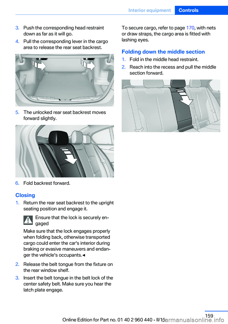
3.Push the corresponding head restraint
down as far as it will go.4.Pull the corresponding lever in the cargo
area to release the rear seat backrest.5.The unlocked rear seat backrest moves
forward slightly.6.Fold backrest forward.
Closing
1.Return the rear seat backrest to the upright
seating position and engage it.
Ensure that the lock is securely en‐
gaged
Make sure that the lock engages properly
when folding back, otherwise transported
cargo could enter the car's interior during
braking or evasive maneuvers and endan‐
ger the vehicle's occupants.◀2.Release the belt tongue from the fixture on
the rear window shelf.3.Insert the belt tongue in the belt lock of the
center safety belt. Make sure you hear the
latch plate engage.To secure cargo, refer to page 170, with nets
or draw straps, the cargo area is fitted with
lashing eyes.
Folding down the middle section1.Fold in the middle head restraint.2.Reach into the recess and pull the middle
section forward.Seite 159Interior equipmentControls159
Online Edition for Part no. 01 40 2 960 440 - II/15
Page 174 of 257
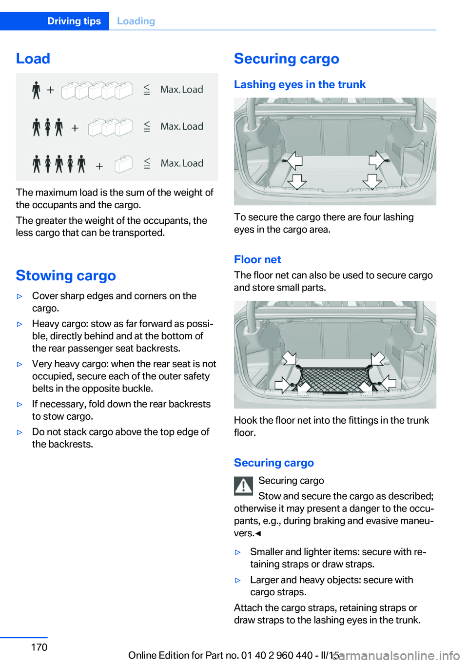
Load
The maximum load is the sum of the weight of
the occupants and the cargo.
The greater the weight of the occupants, the
less cargo that can be transported.
Stowing cargo
▷Cover sharp edges and corners on the
cargo.▷Heavy cargo: stow as far forward as possi‐
ble, directly behind and at the bottom of
the rear passenger seat backrests.▷Very heavy cargo: when the rear seat is not
occupied, secure each of the outer safety
belts in the opposite buckle.▷If necessary, fold down the rear backrests
to stow cargo.▷Do not stack cargo above the top edge of
the backrests.Securing cargo
Lashing eyes in the trunk
To secure the cargo there are four lashing
eyes in the cargo area.
Floor net
The floor net can also be used to secure cargo
and store small parts.
Hook the floor net into the fittings in the trunk
floor.
Securing cargo Securing cargo
Stow and secure the cargo as described;
otherwise it may present a danger to the occu‐
pants, e.g., during braking and evasive maneu‐
vers.◀
▷Smaller and lighter items: secure with re‐
taining straps or draw straps.▷Larger and heavy objects: secure with
cargo straps.
Attach the cargo straps, retaining straps or
draw straps to the lashing eyes in the trunk.
Seite 170Driving tipsLoading170
Online Edition for Part no. 01 40 2 960 440 - II/15