ESP BMW 335I XDRIVE SEDAN 2014 User Guide
[x] Cancel search | Manufacturer: BMW, Model Year: 2014, Model line: 335I XDRIVE SEDAN, Model: BMW 335I XDRIVE SEDAN 2014Pages: 242, PDF Size: 7.25 MB
Page 42 of 242
The alarm system briefly indicates tampering:▷By sounding an acoustic alarm.▷By switching on the hazard warning sys‐
tem.▷By flashing the daytime running lights.
Arming and disarming the alarm
system
General information
When you lock or unlock the vehicle, either
with the remote control or via the Comfort Ac‐
cess at the door lock, the alarm system is
armed or disarmed at the same time.
Door lock and armed alarm systemThe alarm system is triggered when the door is
opened, if the vehicle is unlocked via the door
lock.
In order to terminate this alarm, unlock vehicle
with the remote control or switch on the igni‐
tion, if necessary, by emergency detection of
the remote control.
Trunk lid and armed alarm systemThe trunk lid can be opened even when the
alarm system is armed.
After the trunk lid is closed, it is locked and
monitored again if the doors are locked. The
hazard warning system flashes once.
Panic mode You can trigger the alarm system if you find
yourself in a dangerous situation.
Press the button on the remote con‐
trol for at least 3 seconds.
To switch off the alarm: press any button.
Switching off the alarm To terminate the alarm:
▷Unlock the vehicle using the remote con‐
trol.▷With Comfort Access: If you are carrying
the remote control with you, grasp the
driver side or front passenger side door
handle completely.
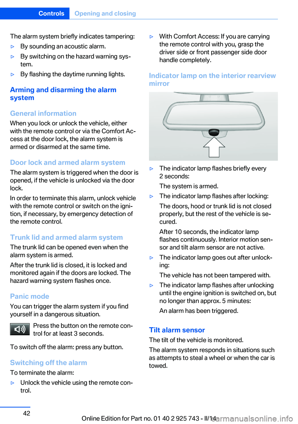
Indicator lamp on the interior rearview
mirror
▷The indicator lamp flashes briefly every
2 seconds:
The system is armed.▷The indicator lamp flashes after locking:
The doors, hood or trunk lid is not closed
properly, but the rest of the vehicle is se‐
cured.
After 10 seconds, the indicator lamp
flashes continuously. Interior motion sen‐
sor and tilt alarm sensor are not active.▷The indicator lamp goes out after unlock‐
ing:
The vehicle has not been tampered with.▷The indicator lamp flashes after unlocking
until the engine ignition is switched on, but
no longer than approx. 5 minutes:
An alarm has been triggered.
Tilt alarm sensor The tilt of the vehicle is monitored.
The alarm system responds in situations such
as attempts to steal a wheel or when the car is
towed.
Seite 42ControlsOpening and closing42
Online Edition for Part no. 01 40 2 925 743 - II/14
Page 45 of 242
Glass sunroof, poweredGeneral information
The glass sunroof is operational when the igni‐
tion is switched on.
Keep the closing path clear
Monitor the closing process and make
sure that the closing path of the glass sunroof
is clear; otherwise, injuries may result.◀
Take the remote control with youTake the remote control with you when
leaving the vehicle so that children, for exam‐
ple, cannot operate the roof and injure them‐
selves.◀
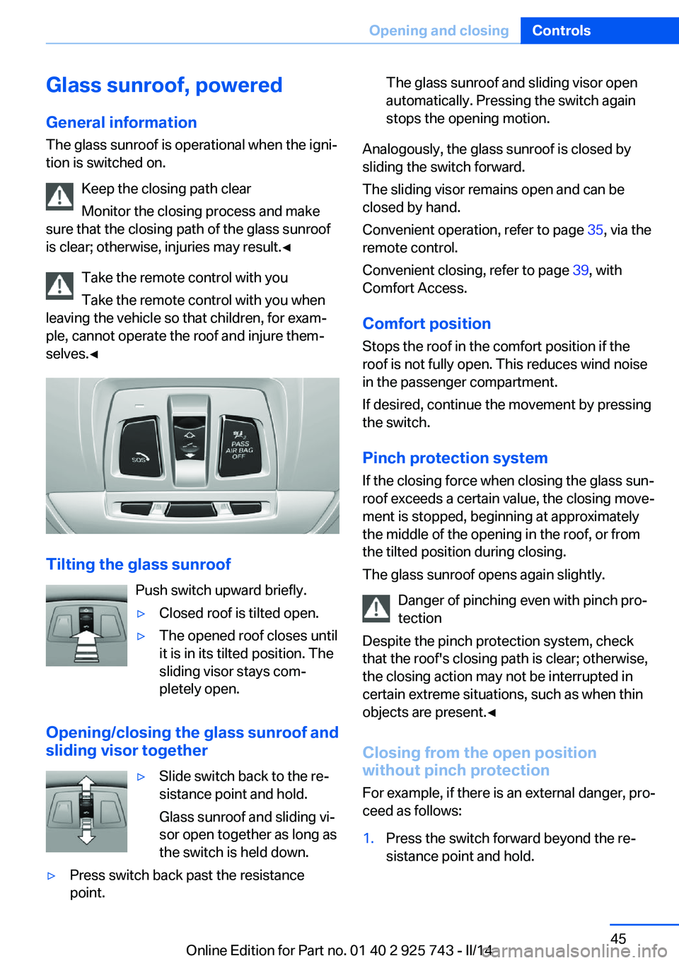
Tilting the glass sunroof
Push switch upward briefly.
▷Closed roof is tilted open.▷The opened roof closes until
it is in its tilted position. The
sliding visor stays com‐
pletely open.
Opening/closing the glass sunroof and
sliding visor together
▷Slide switch back to the re‐
sistance point and hold.
Glass sunroof and sliding vi‐
sor open together as long as
the switch is held down.▷Press switch back past the resistance
point.The glass sunroof and sliding visor open
automatically. Pressing the switch again
stops the opening motion.
Analogously, the glass sunroof is closed by
sliding the switch forward.
The sliding visor remains open and can be
closed by hand.
Convenient operation, refer to page 35, via the
remote control.
Convenient closing, refer to page 39, with
Comfort Access.
Comfort position
Stops the roof in the comfort position if the
roof is not fully open. This reduces wind noise
in the passenger compartment.
If desired, continue the movement by pressing
the switch.
Pinch protection system
If the closing force when closing the glass sun‐
roof exceeds a certain value, the closing move‐
ment is stopped, beginning at approximately
the middle of the opening in the roof, or from
the tilted position during closing.
The glass sunroof opens again slightly.
Danger of pinching even with pinch pro‐
tection
Despite the pinch protection system, check
that the roof's closing path is clear; otherwise,
the closing action may not be interrupted in
certain extreme situations, such as when thin
objects are present.◀
Closing from the open position
without pinch protection
For example, if there is an external danger, pro‐
ceed as follows:
1.Press the switch forward beyond the re‐
sistance point and hold.Seite 45Opening and closingControls45
Online Edition for Part no. 01 40 2 925 743 - II/14
Page 47 of 242
AdjustingVehicle equipment
All standard, country-specific and optional
equipment that is offered in the model series is
described in this chapter. Therefore, equip‐
ment is also described that is not available in a
vehicle, e. g., because of the selected optional
equipment or country variant. This also applies
for safety-related functions and systems.
Sitting safely The ideal seating position can make a vital
contribution to relaxed, fatigue-free driving.
The seating position plays an important role in
an accident in combination with:▷Safety belts, refer to page 50.▷Head restraints, refer to page 51.▷Airbags, refer to page 94.
Seats
Hints Do not adjust the seat while driving
Do not adjust the driver's seat while driv‐
ing, or the seat could respond with unexpected
movement and the ensuing loss of vehicle
control could lead to an accident.◀
Do not incline the backrest too far to the
rear
Also on the front passenger side, do not incline
the backrest on the front passenger side too far to the rear during driving, or there is a risk of
slipping under the safety belt in the event of an
accident. This would eliminate the protection
normally provided by the belt.◀
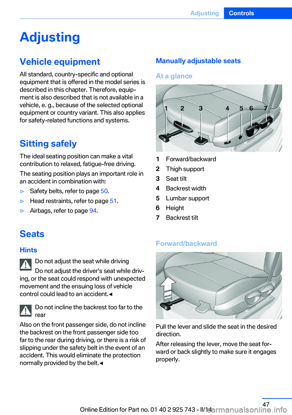
Manually adjustable seats
At a glance1Forward/backward2Thigh support3Seat tilt4Backrest width5Lumbar support6Height7Backrest tilt
Forward/backward
Pull the lever and slide the seat in the desired
direction.
After releasing the lever, move the seat for‐
ward or back slightly to make sure it engages
properly.
Seite 47AdjustingControls47
Online Edition for Part no. 01 40 2 925 743 - II/14
Page 54 of 242
General information
Two different driver's seat and exterior mirror
positions can be stored and retrieved for each
remote control. Settings for the backrest width
and lumbar support are not stored in memory.
Storing
1.Switch on the ignition.2.Set the desired position.3. Press the button. The LED in the
button lights up.4.Press the desired button 1 or 2. The LED
goes out.
If the M button is pressed accidentally:
Press the button again.
The LED goes out.
Calling up settings
Comfort function
1.Open the driver's door.2.Switch off the ignition.3.Briefly press the desired button 1 or 2.
The corresponding seat position is performed
automatically.
The procedure stops when a switch for adjust‐
ing the seat or one of the buttons is pressed.
Safety mode
1.Close the driver's door or switch on the ig‐
nition.2.Press and hold the desired button 1 or 2
until the adjustment procedure is com‐
pleted.
Calling up of a seat position
deactivated
After a brief period, the calling up of stored
seat positions is deactivated to save battery
power.
To reactivate calling up of a seat position:
▷Open and close the door or trunk lid.▷Press a button on the remote control.▷Press the Start/Stop button.
Mirrors
Exterior mirrors
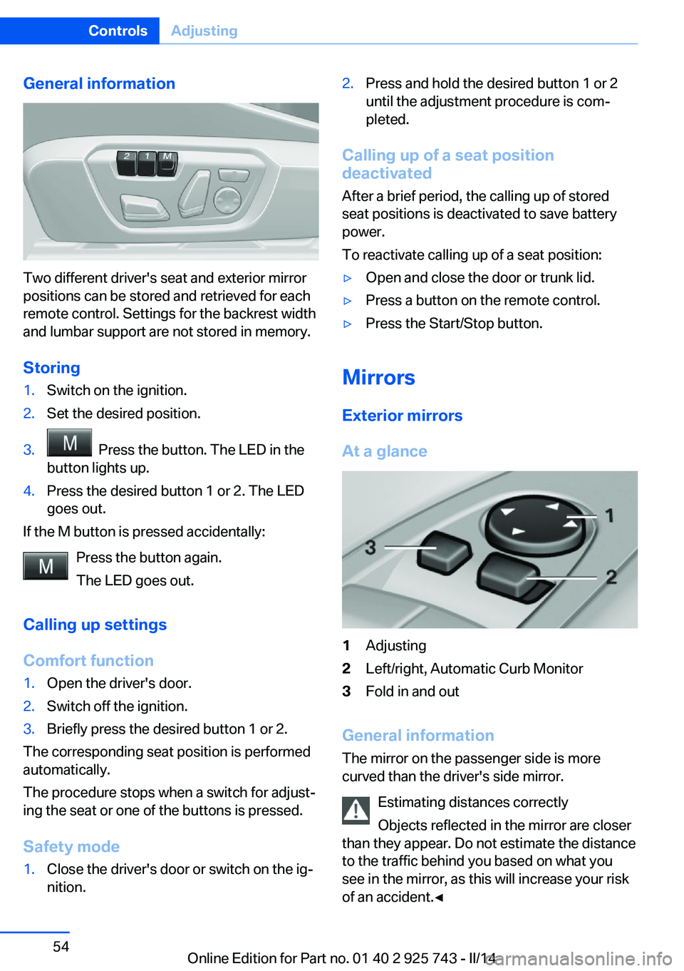
At a glance
1Adjusting2Left/right, Automatic Curb Monitor3Fold in and out
General information
The mirror on the passenger side is more
curved than the driver's side mirror.
Estimating distances correctly
Objects reflected in the mirror are closer
than they appear. Do not estimate the distance
to the traffic behind you based on what you
see in the mirror, as this will increase your risk
of an accident.◀
Seite 54ControlsAdjusting54
Online Edition for Part no. 01 40 2 925 743 - II/14
Page 55 of 242
Depending on how the vehicle is equipped, the
mirror setting is stored for the remote control
in use. When the vehicle is unlocked via the re‐
mote control, the position is automatically re‐
trieved if the setting for this function is active.
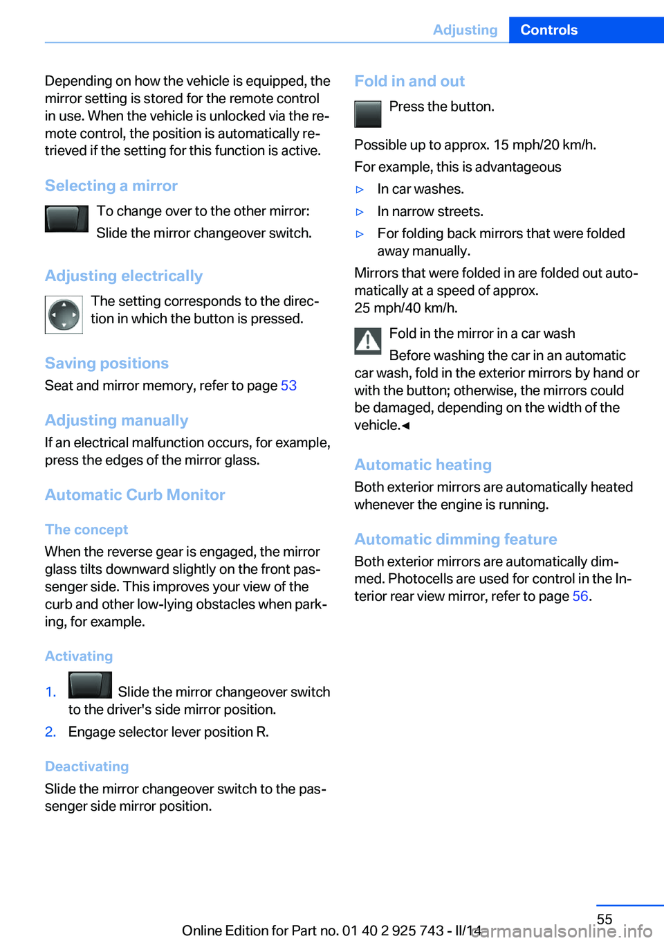
Selecting a mirror To change over to the other mirror:Slide the mirror changeover switch.
Adjusting electrically The setting corresponds to the direc‐
tion in which the button is pressed.
Saving positions Seat and mirror memory, refer to page 53
Adjusting manually If an electrical malfunction occurs, for example,
press the edges of the mirror glass.
Automatic Curb Monitor
The concept
When the reverse gear is engaged, the mirror
glass tilts downward slightly on the front pas‐
senger side. This improves your view of the
curb and other low-lying obstacles when park‐
ing, for example.
Activating1. Slide the mirror changeover switch
to the driver's side mirror position.2.Engage selector lever position R.
Deactivating
Slide the mirror changeover switch to the pas‐
senger side mirror position.
Fold in and out
Press the button.
Possible up to approx. 15 mph/20 km/h.
For example, this is advantageous▷In car washes.▷In narrow streets.▷For folding back mirrors that were folded
away manually.
Mirrors that were folded in are folded out auto‐
matically at a speed of approx.
25 mph/40 km/h.
Fold in the mirror in a car wash
Before washing the car in an automatic
car wash, fold in the exterior mirrors by hand or
with the button; otherwise, the mirrors could
be damaged, depending on the width of the
vehicle.◀
Automatic heating
Both exterior mirrors are automatically heated
whenever the engine is running.
Automatic dimming feature Both exterior mirrors are automatically dim‐
med. Photocells are used for control in the In‐
terior rear view mirror, refer to page 56.
Seite 55AdjustingControls55
Online Edition for Part no. 01 40 2 925 743 - II/14
Page 83 of 242
▷When signs are concealed by objects.▷When driving very close to the vehicle in
front of you.▷When driving toward bright lights.▷When the windshield behind the interior
rearview mirror is fogged over, dirty or cov‐
ered by a sticker, etc.▷In the event of incorrect detection by the
camera.▷If the speed limits stored in the navigation
system are incorrect.▷In areas not covered by the navigation sys‐
tem.▷When roads differ from the navigation,
such as due to changes in the road net‐
work.▷When passing buses or trucks with a
speed sticker.▷If the traffic signs are non-conforming.▷During calibration of the camera immedi‐
ately after vehicle shipment.
Selection lists in the
instrument cluster
The concept Depending on the equipment version, the fol‐
lowing can be displayed or operated using the
buttons and the thumbwheel on the steering
wheel and the displays in the instrument clus‐
ter and the Head-up Display:
▷Current audio source.▷Redial on telephone.▷Activation of the voice activation system.
In addition, programs of the Driving Dynamics
Control are displayed.
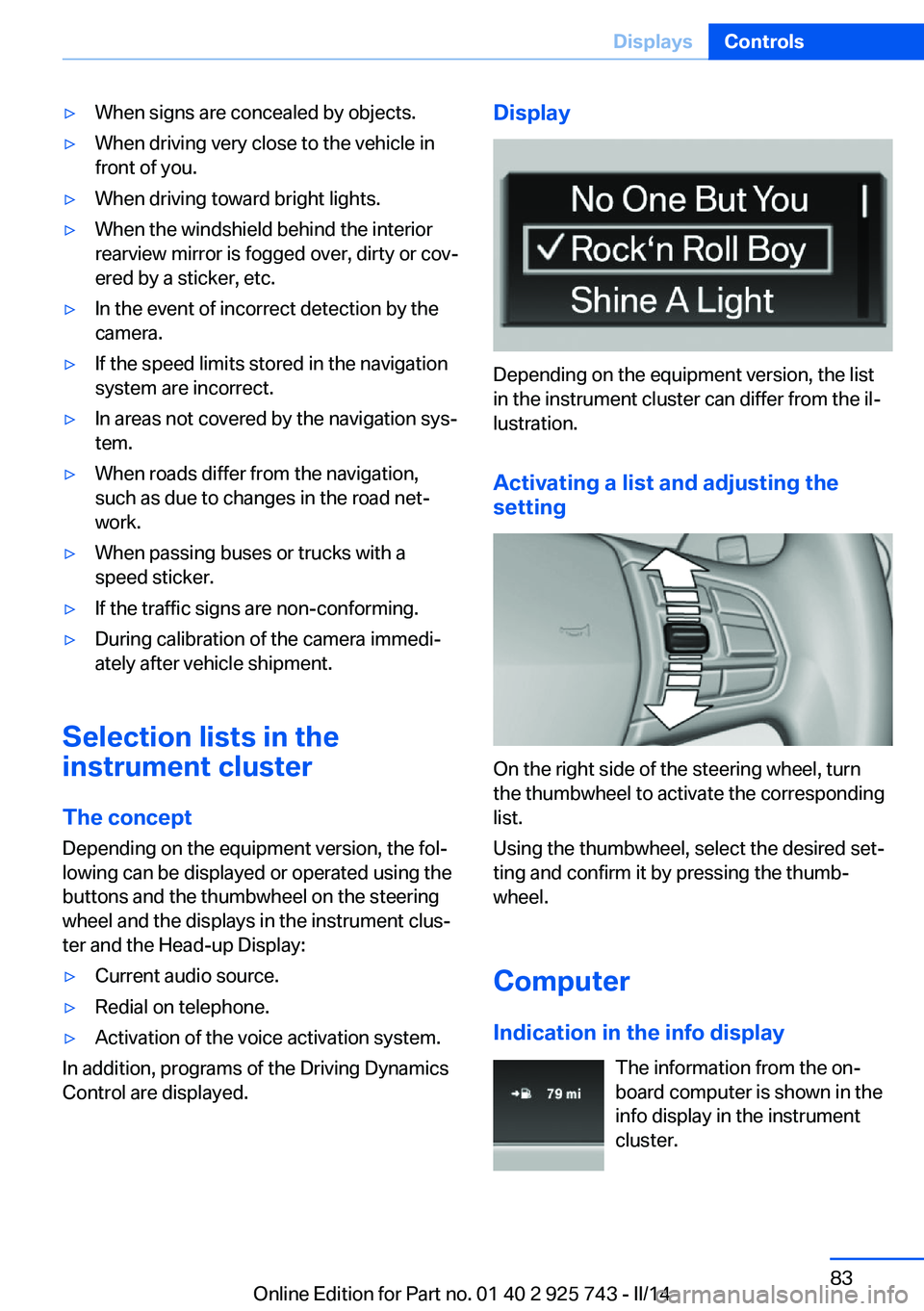
Display
Depending on the equipment version, the list
in the instrument cluster can differ from the il‐
lustration.
Activating a list and adjusting the
setting
On the right side of the steering wheel, turn
the thumbwheel to activate the corresponding
list.
Using the thumbwheel, select the desired set‐
ting and confirm it by pressing the thumb‐
wheel.
Computer
Indication in the info display The information from the on‐
board computer is shown in the
info display in the instrument
cluster.
Seite 83DisplaysControls83
Online Edition for Part no. 01 40 2 925 743 - II/14
Page 90 of 242
3."Pathway lighting:"4.Set the duration.
The setting is stored for the remote control
currently in use.
Automatic headlamp control
Switch position
: the low beams are
switched on and off automatically, e.g., in tun‐
nels, in twilight or if there is precipitation. The
indicator lamp in the instrument cluster lights
up.
A blue sky with the sun low on the horizon can
cause the lights to be switched on.
The low beams always stay on when the fog
lamps are switched on.
Personal responsibility
The automatic headlamp control cannot
serve as a substitute for your personal judg‐
ment in determining when the lamps should be
switched on in response to ambient lighting
conditions.
For example, the sensors are unable to detect
fog or hazy weather. To avoid safety risks, you
should always switch on the lamps manually
under these conditions.◀
Daytime running lights With the ignition switched on, the daytime run‐
ning lights light up in position 0,
or .
After the ignition is switched off, the parking
lamps light up in position
.
Activating/deactivating
In some countries, daytime running lights are
compulsory, so it may not be possible to deac‐
tivate the daytime running lights.
1."Settings"2."Lighting"3."Daytime running lamps"
The setting is stored for the remote control
currently in use.
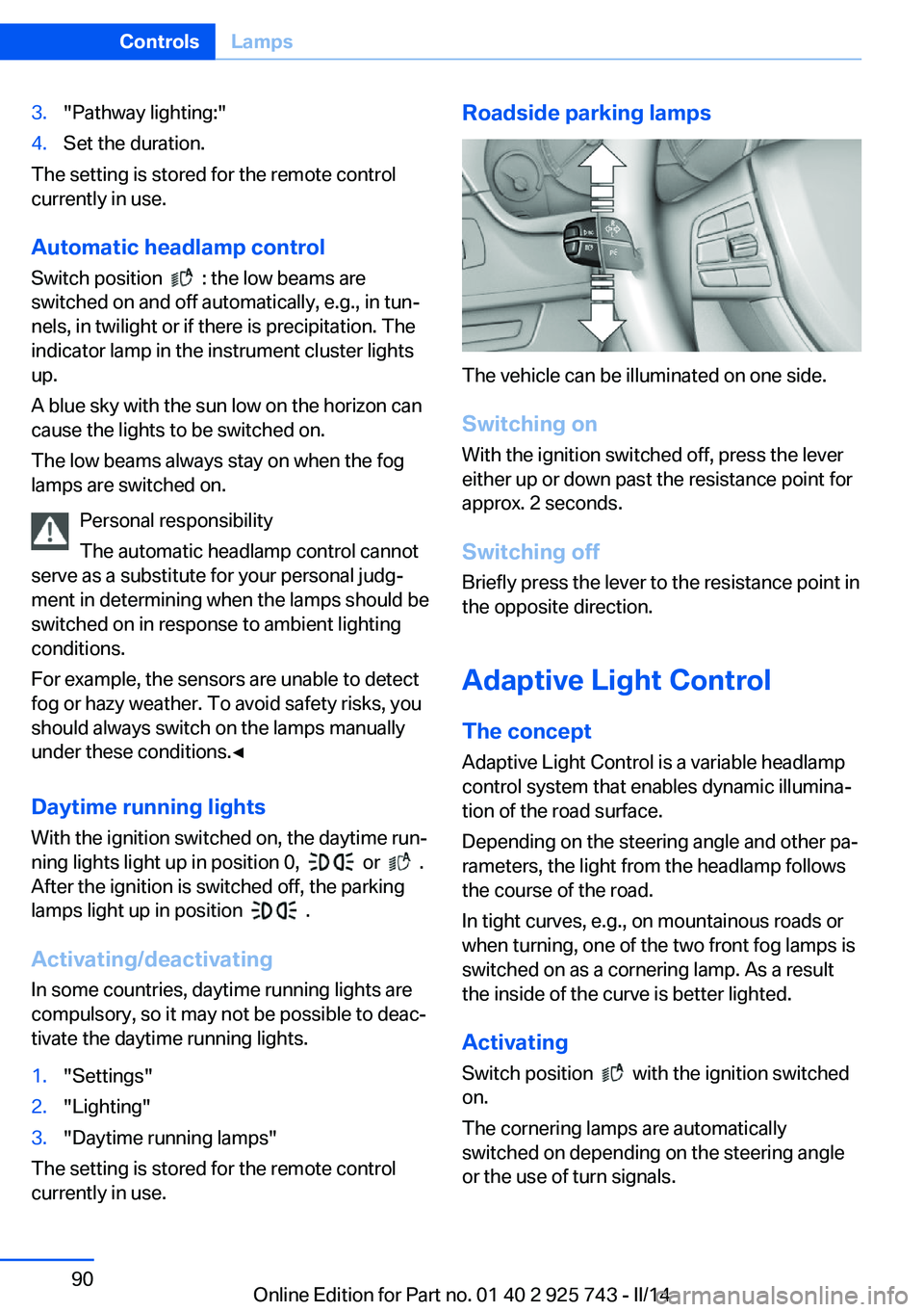
Roadside parking lamps
The vehicle can be illuminated on one side.
Switching on With the ignition switched off, press the lever
either up or down past the resistance point for
approx. 2 seconds.
Switching off Briefly press the lever to the resistance point in
the opposite direction.
Adaptive Light Control The conceptAdaptive Light Control is a variable headlamp
control system that enables dynamic illumina‐
tion of the road surface.
Depending on the steering angle and other pa‐
rameters, the light from the headlamp follows
the course of the road.
In tight curves, e.g., on mountainous roads or
when turning, one of the two front fog lamps is
switched on as a cornering lamp. As a result
the inside of the curve is better lighted.
Activating Switch position
with the ignition switched
on.
The cornering lamps are automatically
switched on depending on the steering angle
or the use of turn signals.
Seite 90ControlsLamps90
Online Edition for Part no. 01 40 2 925 743 - II/14
Page 91 of 242
To avoid blinding oncoming traffic, the Adap‐
tive Light Control does not swivel to the driv‐
er's side when the vehicle is at a standstill.
When driving in reverse, only the cornering
lamp is active.
Malfunction
A Check Control message is displayed.
Adaptive light control is malfunctioning or has
failed. Have the system checked as soon as
possible.
High-beam Assistant The concept
When the low beams are switched on, this sys‐
tem automatically switches the high beams on
and off or suppresses the light in the areas that
blind oncoming traffic. The procedure is con‐
trolled by a sensor on the front of the interior
rearview mirror. The assistant ensures that the
high beams are switched on whenever the traf‐
fic situation allows. The driver can intervene at
any time and switch the high beams on and off as usual.
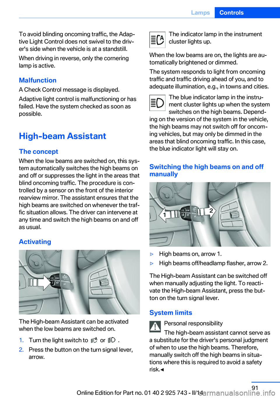
Activating
The High-beam Assistant can be activated
when the low beams are switched on.
1.Turn the light switch to or .2.Press the button on the turn signal lever,
arrow.The indicator lamp in the instrument
cluster lights up.
When the low beams are on, the lights are au‐
tomatically brightened or dimmed.
The system responds to light from oncoming
traffic and traffic driving ahead of you, and to
adequate illumination, e.g., in towns and cities.
The blue indicator lamp in the instru‐
ment cluster lights up when the system
switches on the high beams. Depend‐
ing on the version of the system in the vehicle, the high beams may not switch off for oncom‐
ing vehicles, but may only be dimmed in the
areas that blind oncoming traffic. In this case,
the blue indicator light will stay on.
Switching the high beams on and off
manually▷High beams on, arrow 1.▷High beams off/headlamp flasher, arrow 2.
The High-beam Assistant can be switched off
when manually adjusting the light. To reacti‐
vate the High-beam Assistant, press the but‐
ton on the turn signal lever.
System limits Personal responsibility
The high-beam assistant cannot serve as
a substitute for the driver's personal judgment
of when to use the high beams. Therefore,
manually switch off the high beams in situa‐
tions where this is required to avoid a safety
risk.◀
Seite 91LampsControls91
Online Edition for Part no. 01 40 2 925 743 - II/14
Page 94 of 242
SafetyVehicle equipment
All standard, country-specific and optional
equipment that is offered in the model series is
described in this chapter. Therefore, equip‐ment is also described that is not available in a
vehicle, e. g., because of the selected optional
equipment or country variant. This also applies
for safety-related functions and systems.
Airbags
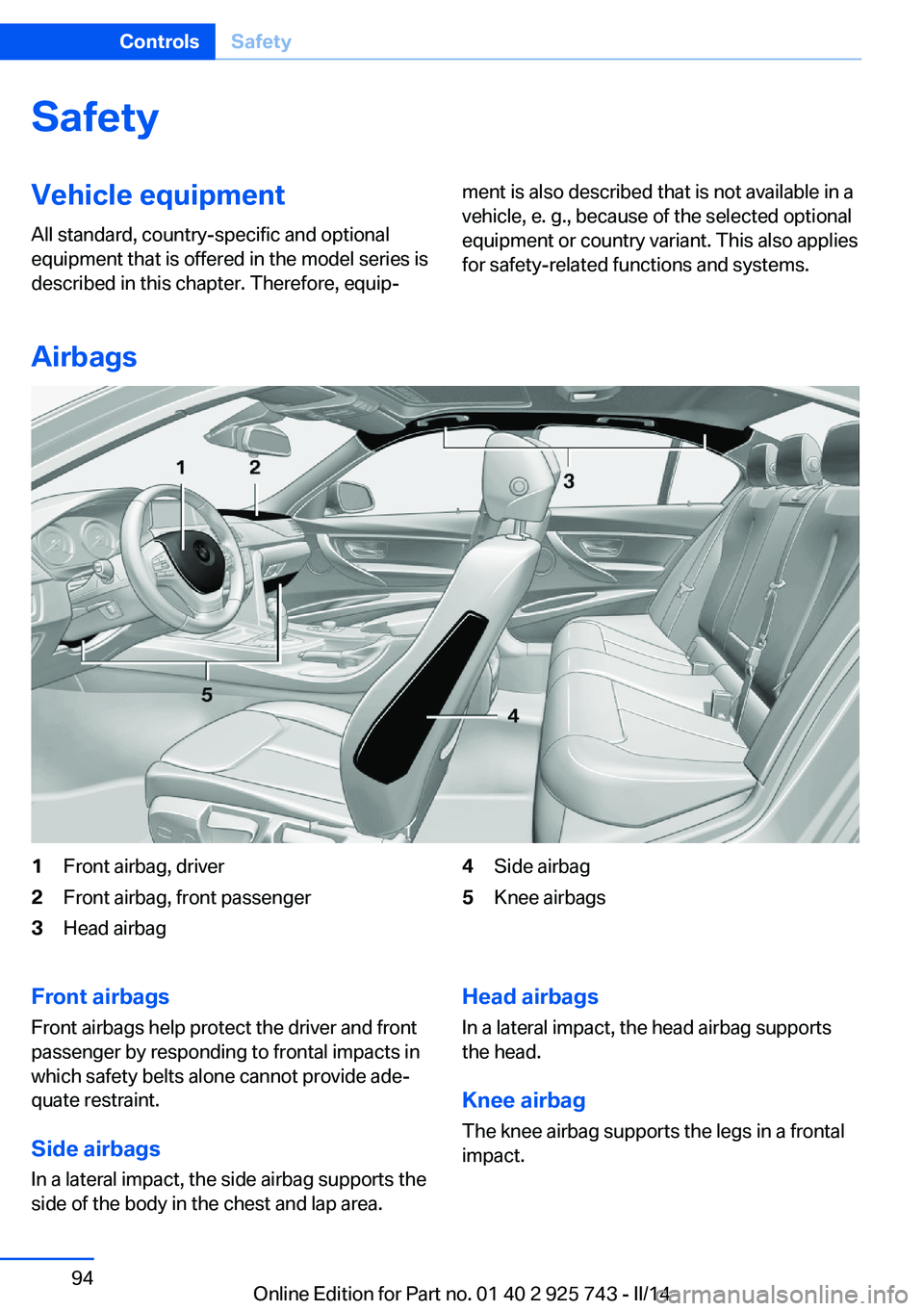
1Front airbag, driver2Front airbag, front passenger3Head airbag4Side airbag5Knee airbagsFront airbags
Front airbags help protect the driver and front
passenger by responding to frontal impacts in
which safety belts alone cannot provide ade‐
quate restraint.
Side airbags
In a lateral impact, the side airbag supports the
side of the body in the chest and lap area.Head airbags
In a lateral impact, the head airbag supports
the head.
Knee airbagThe knee airbag supports the legs in a frontal
impact.Seite 94ControlsSafety94
Online Edition for Part no. 01 40 2 925 743 - II/14
Page 96 of 242
When there is a malfunction, have the
airbag system checked immediately
When there is a malfunction, have the airbag
system checked immediately; otherwise, there
is a risk that the system does not function as
expected in the event of an accident despite
corresponding severity of the accident.◀
Automatic deactivation of the front passenger airbags
The system determines whether the front pas‐
senger seat is occupied by measuring the re‐
sistance of the human body.
The front, knee, and side airbag on the front passenger side are activated or deactivated
accordingly.
Leave feet in the footwell
Make sure that the front passenger
keeps his or her feet in the footwell; otherwise,
the front passenger airbags may not function properly.◀
Child restraint fixing system in the front
passenger seat
Before transporting a child on the front pas‐
senger seat, refer to the safety notes and in‐
structions under Children on the front passen‐
ger seat.◀
Malfunction of the automaticdeactivation system
When transporting older children and adults,
the front passenger airbags may be deacti‐
vated in certain sitting positions. In this case,
the indicator lamp for the front passenger air‐
bags lights up.
In this case, change the sitting position so that
the front passenger airbags are activated and
the indicator lamp goes out.
If it is not possible to activate the airbags, have
the person sit in the rear.
To make sure that the occupied seat cushion
can be evaluated correctly▷Do not attach covers, cushions, ball mats
or other items to the front passenger seat
unless they are specifically recommended
by the manufacturer of your vehicle.▷Do not place any electronic devices on the
passenger seat if a child restraint system is
to be installed on it.▷Do not place objects under the seat that
could press against the seat from below.▷No moisture in or on the seat.
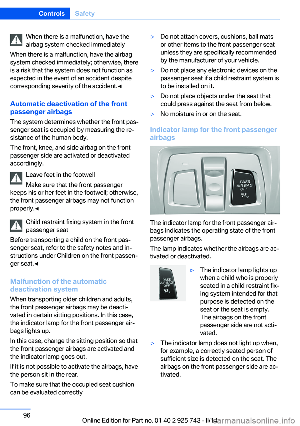
Indicator lamp for the front passenger
airbags
The indicator lamp for the front passenger air‐
bags indicates the operating state of the front
passenger airbags.
The lamp indicates whether the airbags are ac‐
tivated or deactivated.
▷The indicator lamp lights up
when a child who is properly
seated in a child restraint fix‐
ing system intended for that
purpose is detected on the
seat or the seat is empty.
The airbags on the front
passenger side are not acti‐
vated.▷The indicator lamp does not light up when,
for example, a correctly seated person of
sufficient size is detected on the seat. The
airbags on the front passenger side are ac‐
tivated.Seite 96ControlsSafety96
Online Edition for Part no. 01 40 2 925 743 - II/14