trunk BMW 4 SERIES COUPE 2014 F32 User Guide
[x] Cancel search | Manufacturer: BMW, Model Year: 2014, Model line: 4 SERIES COUPE, Model: BMW 4 SERIES COUPE 2014 F32Pages: 244, PDF Size: 6.13 MB
Page 138 of 244
▷Keep the sensors clean and free of ice.▷dimmedDo not put any stickers on sen‐
sors.▷When using high-pressure washers, do not
spray the sensors for long periods and
maintain a distance of at least 12 in/30 cm.
Surround View
The concept Surround View comprises various camera as‐
sistance systems that help the driver when
parking, maneuvering, and at complex exits
and intersections.
▷Rearview camera, refer to page 134▷Side View, refer to page 136.▷Top View, refer to page 137.
Rearview camera
The concept The rearview camera provides assistance in
parking and maneuvering backwards. The area
behind the vehicle is shown on the Control
Display.
Hints Check the traffic situation as well
Check the traffic situation around the ve‐
hicle with your own eyes. Otherwise, an acci‐
dent could result from road users or objects
that are not lidtured by the camera.◀
At a glance
Button in the vehicle
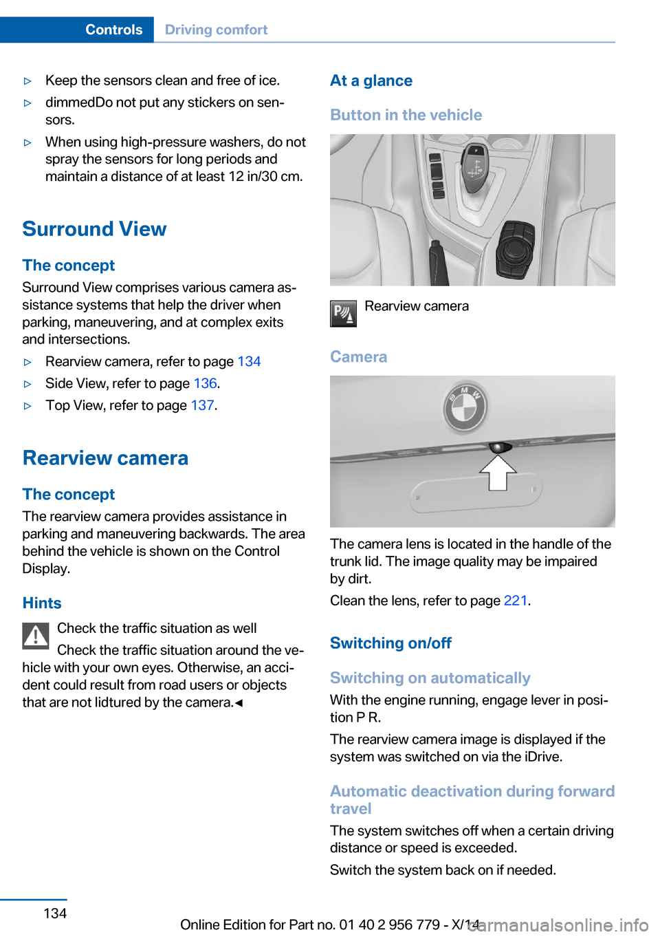
Rearview camera
Camera
The camera lens is located in the handle of the
trunk lid. The image quality may be impaired
by dirt.
Clean the lens, refer to page 221.
Switching on/off
Switching on automatically With the engine running, engage lever in posi‐
tion P R.
The rearview camera image is displayed if the
system was switched on via the iDrive.
Automatic deactivation during forward
travel
The system switches off when a certain driving
distance or speed is exceeded.
Switch the system back on if needed.
Seite 134ControlsDriving comfort134
Online Edition for Part no. 01 40 2 956 779 - X/14
Page 139 of 244
Switching on/off manuallyPress button.▷On: the LED lights up.▷Off: the LED goes out.
The PDC is shown on the Control Display.
Switching the view via iDrive With PDC activated or Top View switched on:
"Rear view camera"
The rearview camera image is displayed.
Display on the Control Display
Functional requirement
▷The rearview camera is switched on.▷The trunk lid is fully closed.
Activating assistance functions
More than one assistance function can be ac‐
tive at the same time.
▷Parking aid lines
"Parking aid lines"
Lanes and turning radius are indicated.
▷Obstacle marking
"Obstacle marking"
Spatially-shaped markings are displayed.
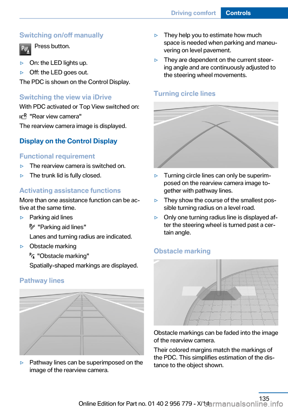
Pathway lines
▷Pathway lines can be superimposed on the
image of the rearview camera.▷They help you to estimate how much
space is needed when parking and maneu‐
vering on level pavement.▷They are dependent on the current steer‐
ing angle and are continuously adjusted to
the steering wheel movements.
Turning circle lines
▷Turning circle lines can only be superim‐
posed on the rearview camera image to‐
gether with pathway lines.▷They show the course of the smallest pos‐
sible turning radius on a level road.▷Only one turning radius line is displayed af‐
ter the steering wheel is turned past a cer‐
tain angle.
Obstacle marking
Obstacle markings can be faded into the image
of the rearview camera.
Their colored margins match the markings of
the PDC. This simplifies estimation of the dis‐
tance to the object shown.
Seite 135Driving comfortControls135
Online Edition for Part no. 01 40 2 956 779 - X/14
Page 143 of 244
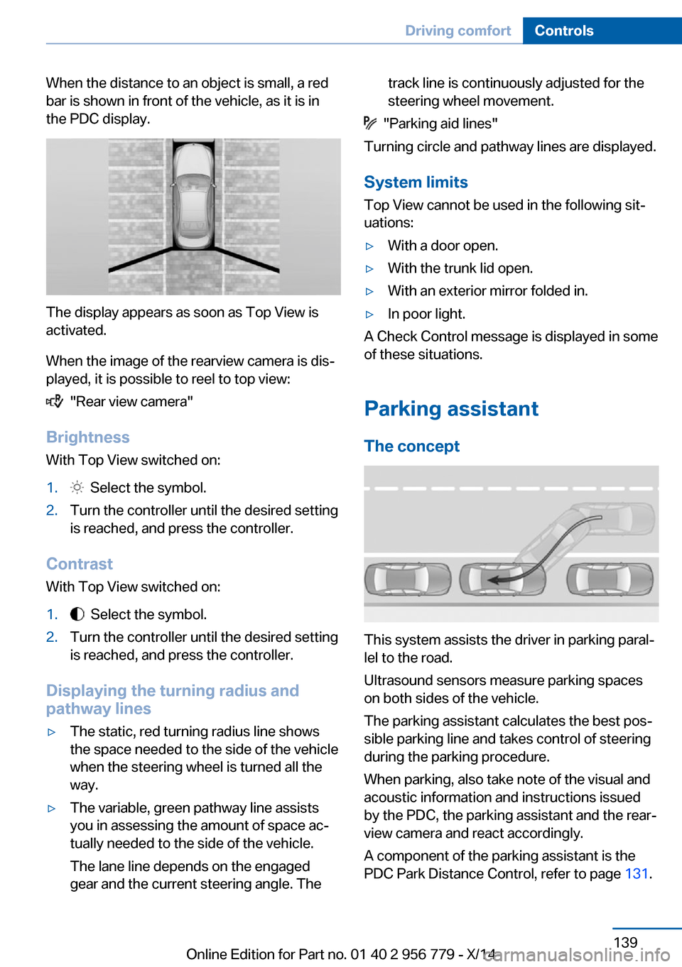
When the distance to an object is small, a red
bar is shown in front of the vehicle, as it is in
the PDC display.
The display appears as soon as Top View is
activated.
When the image of the rearview camera is dis‐
played, it is possible to reel to top view:
"Rear view camera"
Brightness
With Top View switched on:
1. Select the symbol.2.Turn the controller until the desired setting
is reached, and press the controller.
Contrast
With Top View switched on:
1. Select the symbol.2.Turn the controller until the desired setting
is reached, and press the controller.
Displaying the turning radius and
pathway lines
▷The static, red turning radius line shows
the space needed to the side of the vehicle
when the steering wheel is turned all the
way.▷The variable, green pathway line assists
you in assessing the amount of space ac‐
tually needed to the side of the vehicle.
The lane line depends on the engaged
gear and the current steering angle. Thetrack line is continuously adjusted for the
steering wheel movement.
"Parking aid lines"
Turning circle and pathway lines are displayed.
System limits
Top View cannot be used in the following sit‐
uations:
▷With a door open.▷With the trunk lid open.▷With an exterior mirror folded in.▷In poor light.
A Check Control message is displayed in some
of these situations.
Parking assistant The concept
This system assists the driver in parking paral‐
lel to the road.
Ultrasound sensors measure parking spaces
on both sides of the vehicle.
The parking assistant calculates the best pos‐
sible parking line and takes control of steering
during the parking procedure.
When parking, also take note of the visual and
acoustic information and instructions issued
by the PDC, the parking assistant and the rear‐
view camera and react accordingly.
A component of the parking assistant is the
PDC Park Distance Control, refer to page 131.
Seite 139Driving comfortControls139
Online Edition for Part no. 01 40 2 956 779 - X/14
Page 144 of 244
HintsPersonal responsibility
Even an active system does not relieve
the driver from personal responsibility while
driving.
Technically the system has its limits, it cannot
independently react to all traffic situations.
Monitor your driving, be on the alert, observe
the vehicle surroundings and other traffic and
react when needed - risk of accident.◀
Changes to the parking space
Changes to the parking space after it was
measured are not taken into account by the system.
Therefore, always be alert and ready to inter‐
vene; otherwise, there is the risk of an acci‐
dent.◀
Transporting cargo
Cargo that extends beyond the perimeter
of the vehicle is not taken into account by the
system during the parking procedure.
Therefore, always be alert and ready to inter‐
vene; otherwise, there is the risk of an acci‐
dent.◀
Curbs
The parking assistant may steer the vehi‐
cle over or onto curb if need be.
Therefore, always be alert and ready to inter‐
vene; otherwise, the wheels, tires, or the vehi‐
cle may become damaged.◀
An engine that has been switched off by the
Auto Start Stop function is restarted automati‐
cally when the parking assistant is activated.
Requirements
For measuring parking spaces▷Maximum speed while driving forward ap‐
prox. 22 mph/35 km/h.▷Maximum distance to row of parked vehi‐
cles: 5 ft/1.5 m.
Suitable parking space
▷Gap between two objects with a minimum
length of approx. 5 ft/1.5 m.▷Min. length of gap between two objects:
your vehicle's length plus approx.
4 ft/1.2 m.▷Minimum depth: approx. 5 ft/1.5 m.
Regarding the parking procedure
▷Doors and trunk lid closed.▷Parking brake released.▷When parking in parking spaces on the
driver's side, the corresponding turn signal
must be set where applicable.
At a glance
Button in the vehicle
Parking assistant
Seite 140ControlsDriving comfort140
Online Edition for Part no. 01 40 2 956 779 - X/14
Page 163 of 244
Storage compartmentsVehicle features and optionsThis chapter describes all standard, country-
specific and optional features offered with the
series. It also describes features that are not
necessarily available in your car, e. g., due to
the selected options or country versions. This
also applies to safety-related functions and
systems.
Hints No loose objects in the car's interior
Do not stow any objects in the car's inte‐
rior without securing them; otherwise, they
may present a danger to occupants e.g., during
braking and evasive maneuvers.◀
Do not place anti-slip mats on the dash‐
board
Do not place anti-slip mats on the dashboard.
The mat materials could damage the dash‐
board.◀
Storage compartments The following storage compartments are avail‐
able in the vehicle interior:▷Glove compartment on the front passenger
side, refer to page 159.▷Glove compartment on the driver's side,
refer to page 160.▷Without Smoker's package: Front storage
compartment, in front of the cupholders,
refer to page 160.▷Storage compartment in the front center
armrest, refer to page 160.▷Compartments in the doors, refer to
page 160.▷Nets on the backrests of the front seats.▷Storage compartment in the rear center
console, refer to page 161.▷Storage compartment between the rear
seats, refer to page 161.
Glove compartment
Front passenger side
Note Close the glove compartment again im‐
mediately
Close the glove compartment immediately af‐
ter use while driving; otherwise, injury may oc‐
cur during accidents.◀
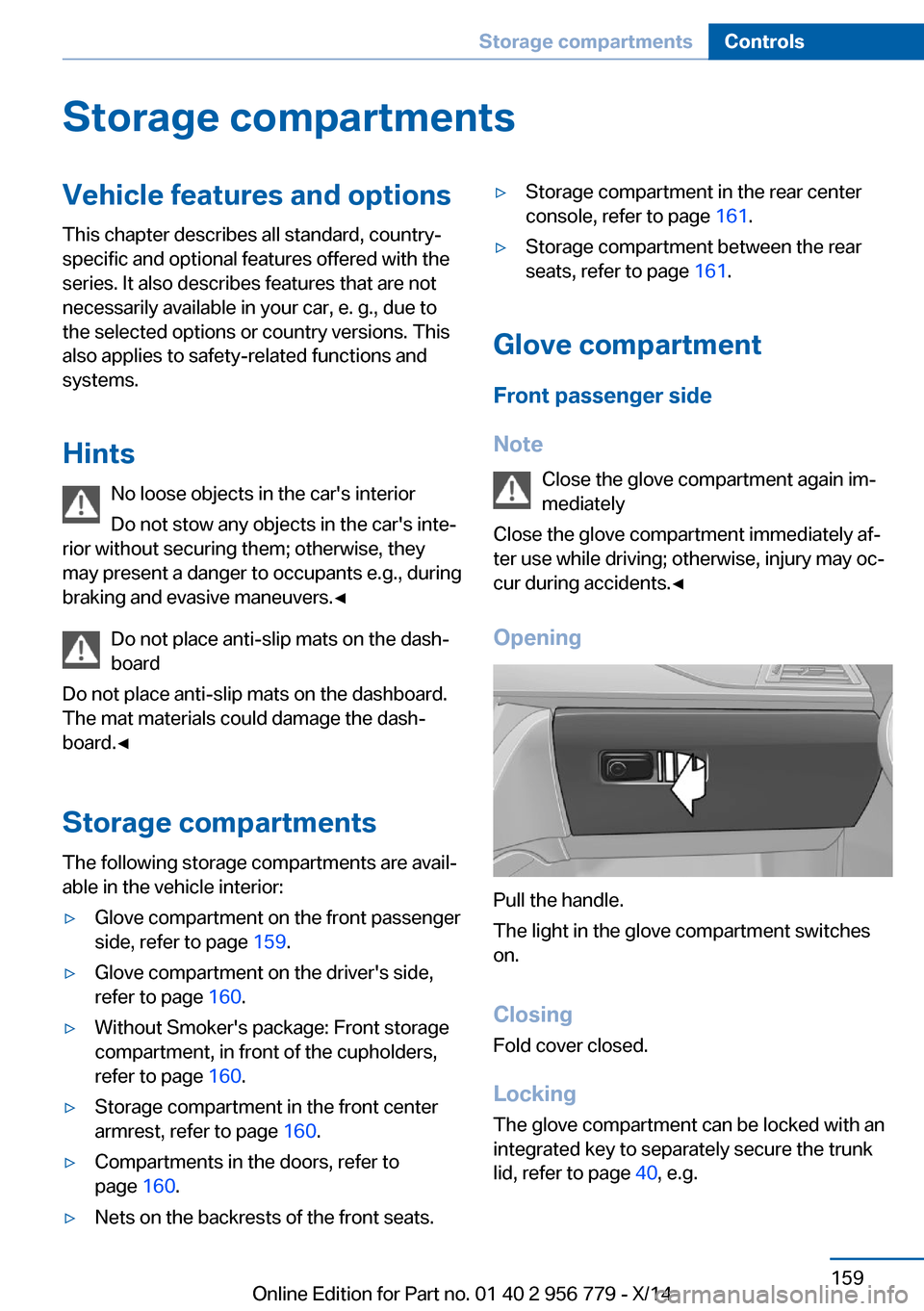
Opening
Pull the handle.
The light in the glove compartment switches
on.
ClosingFold cover closed.
Locking
The glove compartment can be locked with an
integrated key to separately secure the trunk
lid, refer to page 40, e.g.
Seite 159Storage compartmentsControls159
Online Edition for Part no. 01 40 2 956 779 - X/14
Page 170 of 244
Things to remember when drivingVehicle features and options
This chapter describes all standard, country-
specific and optional features offered with the
series. It also describes features that are not
necessarily available in your car, e. g., due to
the selected options or country versions. This
also applies to safety-related functions and
systems.
Breaking-in period
General information Moving parts need time to adjust to one an‐
other (break-in time).
The following instructions will help accomplish
a long vehicle life and good efficiency.
During break-in, do not use the Launch Con‐
trol, refer to page 74.
Engine, transmission, and axle drive Always obey the official speed limit.
Up to 1,200 miles/2,000 km
Do not exceed the maximum engine and road
speed:▷For gasoline engine 4,500 rpm and
100 mph/160 km/h.
Avoid full load or kickdown under all circum‐
stances.
From 1,200 miles/2,000 km The engine and vehicle speed can gradually be
increased.
Tires
Tire traction is not optimal due to manufactur‐
ing circumstances when tires are brand-new;
they achieve their full traction potential after a
break-in time.
Drive conservatively for the first
200 miles/300 km.
Brake system
Brakes require an initial break-in period of ap‐
prox. 300 miles/500 km to achieve optimal per‐
formance between brake discs and brake
pads. Drive moderately during this break-in pe‐
riod.
Clutch The function of the clutch reaches its optimal
level only after a distance driven of approx.
300 miles/500 km. During this break-in period,
engage the clutch gently.
Following part replacement
The same break-in procedures should be ob‐
served if any of the components above-men‐
tioned have to be renewed in the course of the
vehicle's operating life.
General driving notes
Closing the trunk lid Drive with the trunk lid closed
Only drive with the tailgate closed; other‐
wise, in the event of an accident or braking and
evasive maneuvers, passengers and other traf‐
fic may be injured, and the vehicle may be
damaged. In addition, exhaust fumes may en‐
ter the vehicle interior.◀
If driving with the tailgate open cannot be
avoided:▷Close all windows and the glass sunroof.▷Greatly increase the air flow from the vents.▷Drive moderately.Seite 166Driving tipsThings to remember when driving166
Online Edition for Part no. 01 40 2 956 779 - X/14
Page 175 of 244
Securing cargo
Stow and secure the cargo as described
above; otherwise it may present a danger to
the occupants, e.g., during braking and evasive
maneuvers.◀
Roof-mounted luggage rack Note
Roof racks are available as special accessories.
Securing
Follow the installation instructions of the roof
rack.
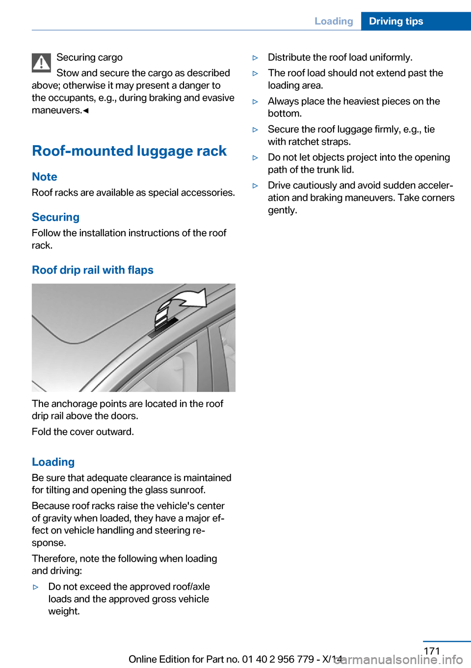
Roof drip rail with flaps
The anchorage points are located in the roof
drip rail above the doors.
Fold the cover outward.
Loading Be sure that adequate clearance is maintained
for tilting and opening the glass sunroof.
Because roof racks raise the vehicle's center
of gravity when loaded, they have a major ef‐
fect on vehicle handling and steering re‐
sponse.
Therefore, note the following when loading
and driving:
▷Do not exceed the approved roof/axle
loads and the approved gross vehicle
weight.▷Distribute the roof load uniformly.▷The roof load should not extend past the
loading area.▷Always place the heaviest pieces on the
bottom.▷Secure the roof luggage firmly, e.g., tie
with ratchet straps.▷Do not let objects project into the opening
path of the trunk lid.▷Drive cautiously and avoid sudden acceler‐
ation and braking maneuvers. Take corners
gently.Seite 171LoadingDriving tips171
Online Edition for Part no. 01 40 2 956 779 - X/14
Page 213 of 244
Outer brake lamp: 21-watt bulb, H21WLL.
The tail lights feature LED technology. Contact
your service center in the event of a malfunc‐
tion.
Use caution when replacing the bulb
Use caution and proceed one step at a
time when replacing the bulbs to prevent dam‐
age to the tail lights or the vehicle.◀
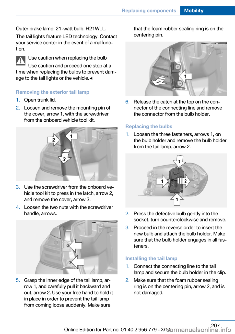
Removing the exterior tail lamp1.Open trunk lid.2.Loosen and remove the mounting pin of
the cover, arrow 1, with the screwdriver
from the onboard vehicle tool kit.3.Use the screwdriver from the onboard ve‐
hicle tool kit to press in the latch, arrow 2,
and remove the cover, arrow 3.4.Loosen the two nuts with the screwdriver
handle, arrows.5.Grasp the inner edge of the tail lamp, ar‐
row 1, and carefully pull it backward and
out, arrow 2. Use your free hand to hold it
in place in order to prevent the tail lamp
from coming loose suddenly. Make surethat the foam rubber sealing ring is on the
centering pin.6.Release the catch at the top on the con‐
nector of the connecting line and remove
the connector from the bulb holder.
Replacing the bulbs
1.Loosen the three fasteners, arrows 1, on
the bulb holder and remove the bulb holder
from the tail lamp, arrow 2.2.Press the defective bulb gently into the
socket, turn counterclockwise and remove.3.Proceed in the reverse order to insert the
new bulb and attach the bulb holder. Make
sure that the bulb holder engages in all fas‐
teners.
Installing the tail lamp
1.Connect the connecting line to the tail
lamp and secure the bulb holder in the clip.2.Make sure that the foam rubber sealing
ring is on the centering pin, arrow 2, and is
not damaged.Seite 207Replacing componentsMobility207
Online Edition for Part no. 01 40 2 956 779 - X/14
Page 214 of 244
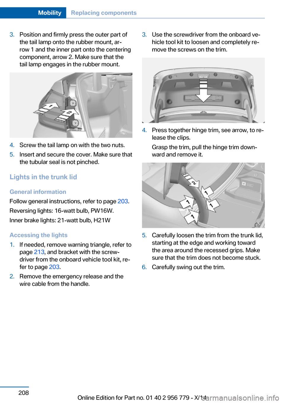
3.Position and firmly press the outer part of
the tail lamp onto the rubber mount, ar‐
row 1 and the inner part onto the centering
component, arrow 2. Make sure that the
tail lamp engages in the rubber mount.4.Screw the tail lamp on with the two nuts.5.Insert and secure the cover. Make sure that
the tubular seal is not pinched.
Lights in the trunk lid
General information
Follow general instructions, refer to page 203.
Reversing lights: 16-watt bulb, PW16W.
Inner brake lights: 21-watt bulb, H21W
Accessing the lights
1.If needed, remove warning triangle, refer to
page 213, and bracket with the screw‐
driver from the onboard vehicle tool kit, re‐
fer to page 203.2.Remove the emergency release and the
wire cable from the handle.3.Use the screwdriver from the onboard ve‐
hicle tool kit to loosen and completely re‐
move the screws on the trim.4.Press together hinge trim, see arrow, to re‐
lease the clips.
Grasp the trim, pull the hinge trim down‐
ward and remove it.5.Carefully loosen the trim from the trunk lid,
starting at the edge and working toward
the area around the recessed grips. Make
sure that the trim does not become stuck.6.Carefully swing out the trim.Seite 208MobilityReplacing components208
Online Edition for Part no. 01 40 2 956 779 - X/14
Page 215 of 244
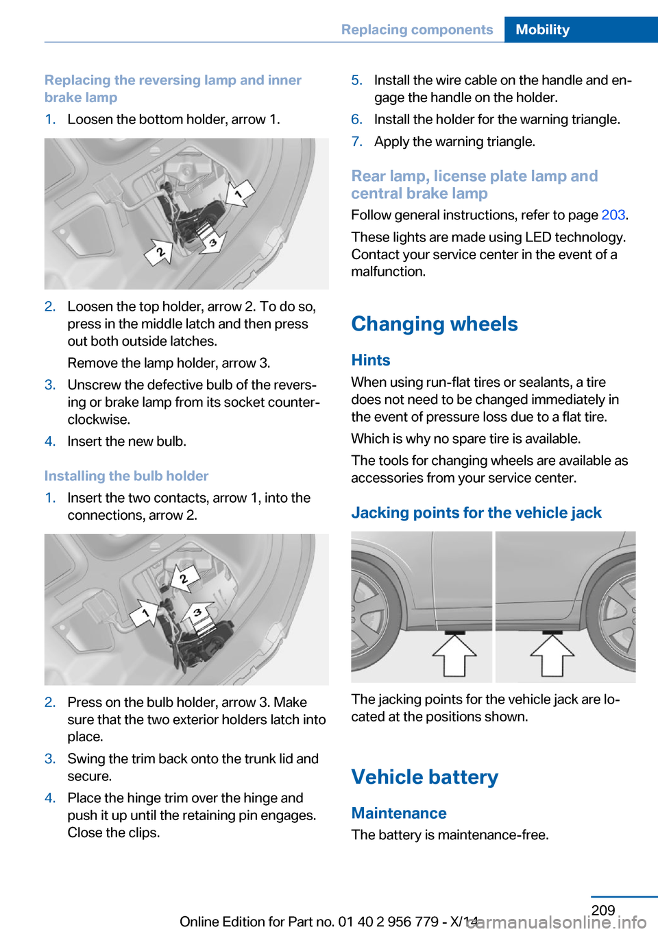
Replacing the reversing lamp and inner
brake lamp1.Loosen the bottom holder, arrow 1.2.Loosen the top holder, arrow 2. To do so,
press in the middle latch and then press
out both outside latches.
Remove the lamp holder, arrow 3.3.Unscrew the defective bulb of the revers‐
ing or brake lamp from its socket counter‐
clockwise.4.Insert the new bulb.
Installing the bulb holder
1.Insert the two contacts, arrow 1, into the
connections, arrow 2.2.Press on the bulb holder, arrow 3. Make
sure that the two exterior holders latch into
place.3.Swing the trim back onto the trunk lid and
secure.4.Place the hinge trim over the hinge and
push it up until the retaining pin engages.
Close the clips.5.Install the wire cable on the handle and en‐
gage the handle on the holder.6.Install the holder for the warning triangle.7.Apply the warning triangle.
Rear lamp, license plate lamp and
central brake lamp
Follow general instructions, refer to page 203.
These lights are made using LED technology.
Contact your service center in the event of a
malfunction.
Changing wheels
Hints When using run-flat tires or sealants, a tire
does not need to be changed immediately in
the event of pressure loss due to a flat tire.
Which is why no spare tire is available.
The tools for changing wheels are available as
accessories from your service center.
Jacking points for the vehicle jack
The jacking points for the vehicle jack are lo‐
cated at the positions shown.
Vehicle battery Maintenance
The battery is maintenance-free.
Seite 209Replacing componentsMobility209
Online Edition for Part no. 01 40 2 956 779 - X/14