Engine compartment BMW 4 SERIES GRAN COUPE 2016 F36 Owner's Manual
[x] Cancel search | Manufacturer: BMW, Model Year: 2016, Model line: 4 SERIES GRAN COUPE, Model: BMW 4 SERIES GRAN COUPE 2016 F36Pages: 249, PDF Size: 5.3 MB
Page 9 of 249
ContentsThe fastest way to find information on a partic‐
ular topic or item is by using the index, refer to
page 234.6Notes
At a glance
14Cockpit18iDrive27Voice activation system30Integrated Owner's Manual in the vehicle
Controls
34Opening and closing51Adjusting61Transporting children safely65Driving78Displays93Lights98Safety120Driving stability control systems125Driving comfort146Climate control153Interior equipment161Storage compartments
Driving tips
168Things to remember when driving171Loading174Saving fuelMobility184Refueling186Fuel188Wheels and tires201Engine compartment203Engine oil206Coolant207Maintenance209Replacing components218Breakdown assistance224Care
Reference
230Technical data234Everything from A to Z
Online Edition for Part no. 01 40 2 960 707 - II/15
Page 13 of 249
cluding the manufacturer, using special diag‐
nostic tools. You can obtain further information
there if you need it. After an error is corrected,
the information in the fault memory is deleted
or overwritten on a continuous basis.
With the vehicle in use there are situations
where you can associate these technical data
with individuals if combined with other infor‐
mation, e.g., an accident report, damage to the
vehicle, eye witness accounts — possibly with
the assistance of an expert.
Additional functions that are contractually
agreed with the customer - such as vehicle
emergency locating - you can transmit certain
vehicle data from the vehicle.
Event Data Recorder EDR
This vehicle is equipped with an event data re‐
corder EDR. The main purpose of an EDR is to
record, in certain crash or near crash-like situa‐
tions, such as an air bag deployment or hitting
a road obstacle, data that will assist in under‐
standing how a vehicle’s systems performed.
The EDR is designed to record data related to
vehicle dynamics and safety systems for a
short period of time, typically 30 seconds or
less.
The EDR in this vehicle is designed to record
such data as:▷How various systems in your vehicle were
operating.▷Whether or not the driver and passenger
safety belts were fastened.▷How far, if at all, the driver was depressing
the accelerator and/or brake pedal.▷How fast the vehicle was traveling.
These data can help provide a better under‐
standing of the circumstances in which
crashes and injuries occur.
EDR data are recorded by your vehicle only if a
nontrivial crash situation occurs; no data are
recorded by the EDR under normal driving
conditions and no personal data, e.g., name,
gender, age, and crash location, are recorded.
However, other parties, such as law enforce‐
ment, could combine the EDR data with the
type of personally identifying data routinely ac‐
quired during a crash investigation.
To read data recorded by an EDR, special
equipment is required, and access to the vehi‐
cle or the EDR is needed. In addition to the ve‐
hicle manufacturer, other parties, such as law
enforcement, that have the special equipment,
can read the information if they have access to
the vehicle or the EDR.
Vehicle identification
number
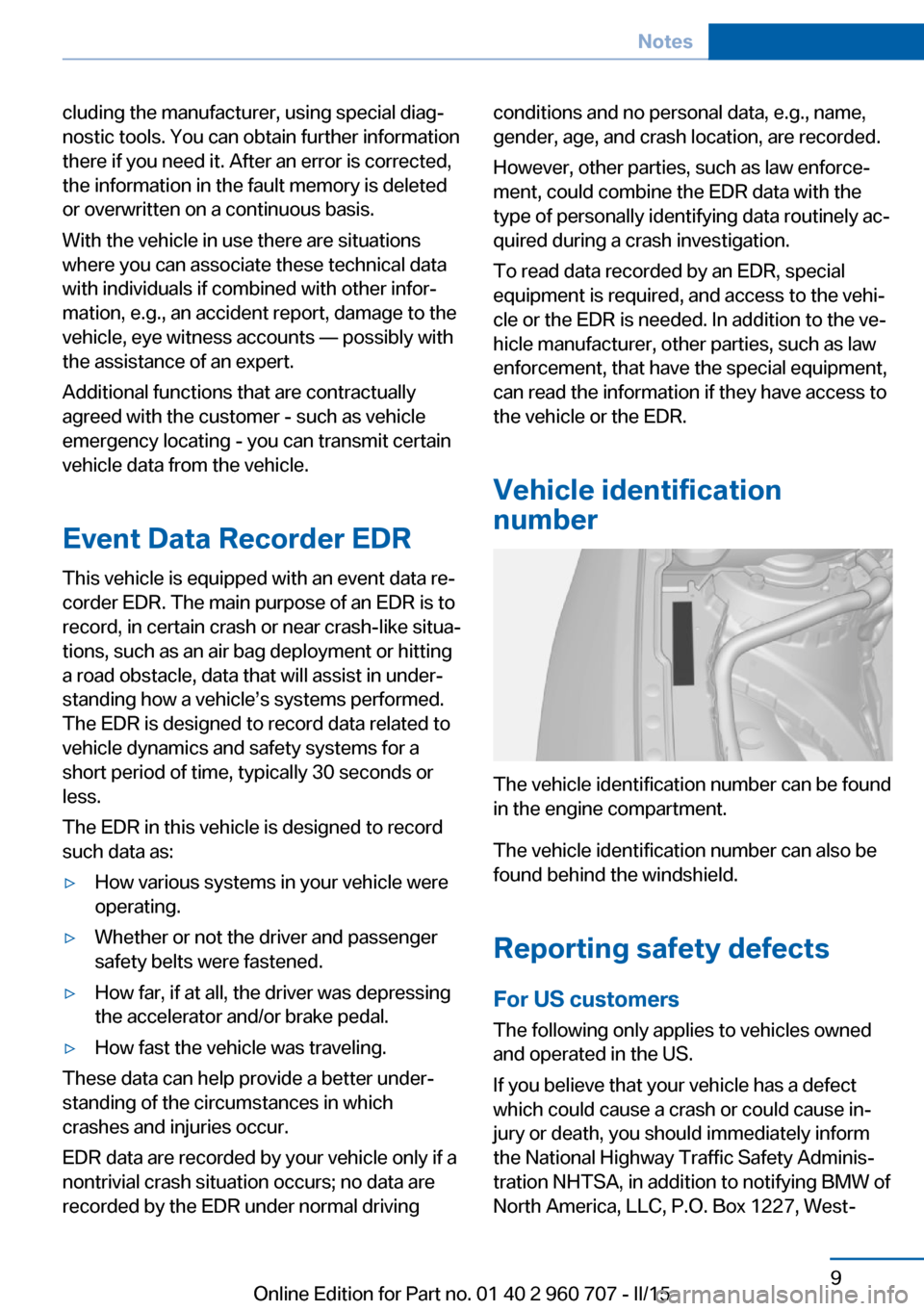
The vehicle identification number can be found
in the engine compartment.
The vehicle identification number can also be
found behind the windshield.
Reporting safety defects
For US customers The following only applies to vehicles owned
and operated in the US.
If you believe that your vehicle has a defect
which could cause a crash or could cause in‐
jury or death, you should immediately inform
the National Highway Traffic Safety Adminis‐
tration NHTSA, in addition to notifying BMW of
North America, LLC, P.O. Box 1227, West‐
Seite 9Notes9
Online Edition for Part no. 01 40 2 960 707 - II/15
Page 72 of 249
▷The engine is not yet at operating temper‐
ature.▷The wheels are at a sharp angle or the
steering wheel is being turned.▷After driving in reverse.▷Fogging of the windows when the auto‐
matic climate control is switched on.▷Vehicle battery is heavily discharged.▷At higher elevations.▷The engine compartment lid is unlocked.▷The parking assistant is activated.▷Stop-and-go traffic.▷The selector lever is in position N, M/S or
R.▷Use of fuel with high ethanol content.
Starting the engine
The engine starts automatically under the fol‐
lowing conditions:
▷Steptronic transmission:
By releasing the brake pedal.▷Manual transmission:
The clutch pedal is pressed.
After the engine starts, accelerate as usual.
Safety mode
After the engine switches off automatically, it
will not start again automatically if any one of
the following conditions are met.
▷The driver's safety belt is unbuckled and
the driver's door is open.▷The hood was unlocked.
Some indicator lights light up for a varied
length of time.
The engine can only be started via the Start/
Stop button.
Functional limitations
Even if driving off was not intended, the deacti‐
vated engine starts up automatically in the fol‐
lowing situations:▷Excessive warming of the car's interior
when the cooling function is switched on.▷The steering wheel is turned.▷Steptronic transmission: change from se‐
lector lever position D to R, N or M/S.▷Steptronic transmission: change from se‐
lector lever position P to N, D, R or M/S.▷The vehicle begins rolling.▷Fogging of the windows when the auto‐
matic climate control is switched on.▷Vehicle battery is heavily discharged.▷Excessive cooling of the car's interior when
the heating is switched on.▷Low brake vacuum pressure; this can oc‐
cur, e.g., if the brake pedal is depressed a
number of times in succession.
Activating/deactivating the system
manually
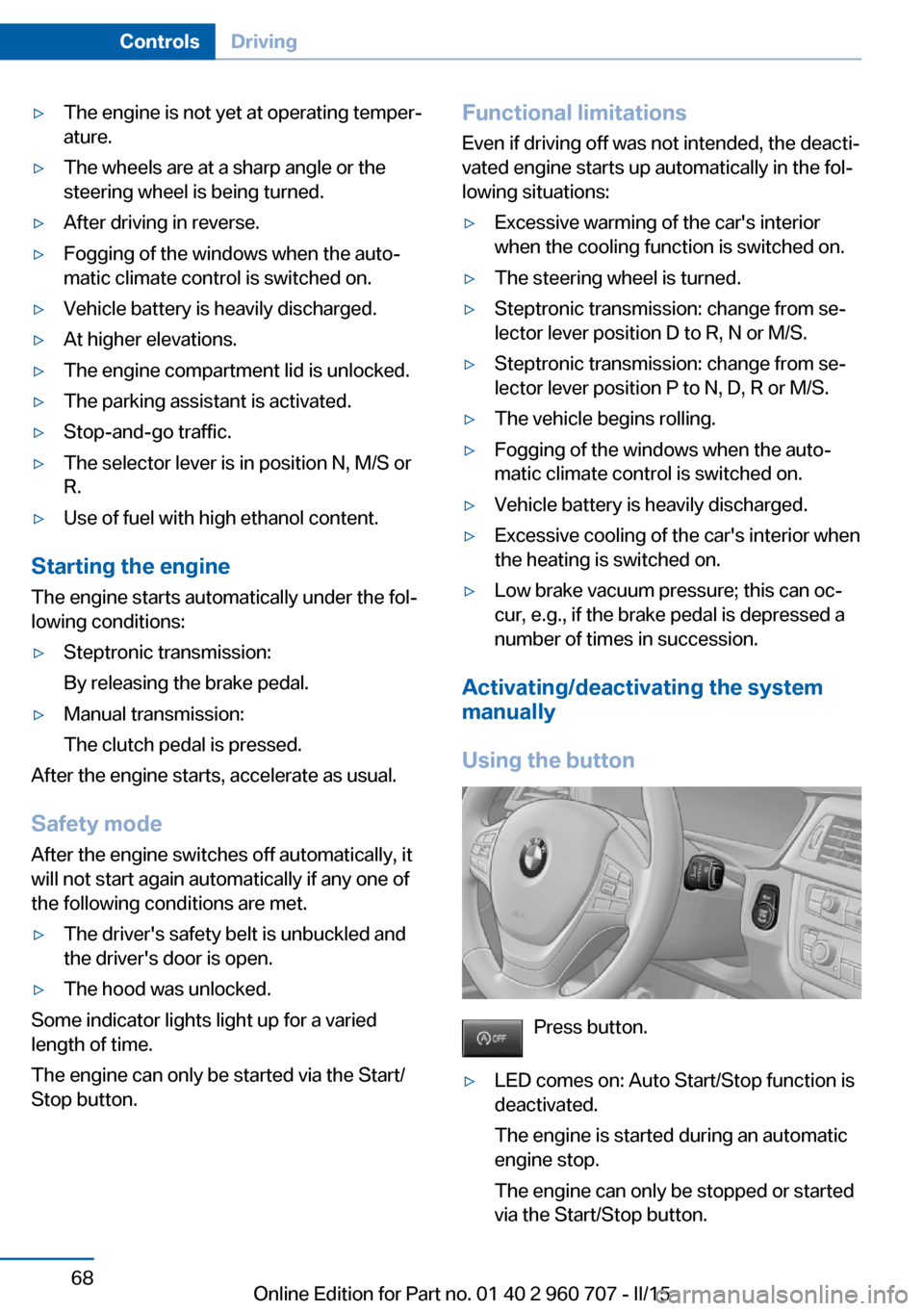
Using the button
Press button.
▷LED comes on: Auto Start/Stop function is
deactivated.
The engine is started during an automatic
engine stop.
The engine can only be stopped or started
via the Start/Stop button.Seite 68ControlsDriving68
Online Edition for Part no. 01 40 2 960 707 - II/15
Page 205 of 249
Engine compartmentVehicle features and optionsThis chapter describes all standard, country-
specific and optional features offered with the
series. It also describes features that are not
necessarily available in your car, e. g., due tothe selected options or country versions. This
also applies to safety-related functions and
systems. The respectively applicable country
provisions must be observed when using the
respective features and systems.
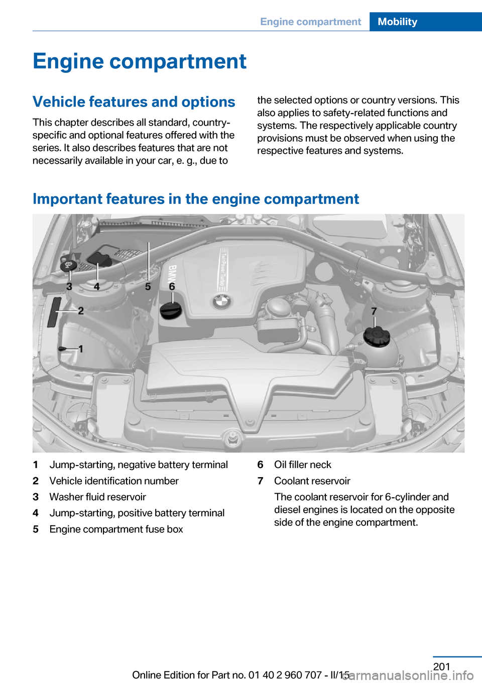
Important features in the engine compartment
1Jump-starting, negative battery terminal2Vehicle identification number3Washer fluid reservoir4Jump-starting, positive battery terminal5Engine compartment fuse box6Oil filler neck7Coolant reservoir
The coolant reservoir for 6-cylinder and
diesel engines is located on the opposite
side of the engine compartment.Seite 201Engine compartmentMobility201
Online Edition for Part no. 01 40 2 960 707 - II/15
Page 206 of 249
Hood
Hints Working in the engine compartment
Never attempt to perform any service or
repair operations on your vehicle without the
necessary professional technical training.
If you are unfamiliar with the statutory guide‐
lines, have any work on the vehicle performed
only by a service center.
If work is not carried out properly, there is a
danger of subsequent damage and related
safety hazards.◀
Never reach into the engine compart‐
ment
Never reach into spaces or gaps in the engine
compartment; otherwise, there is a risk of in‐
jury, e.g., from rotating or hot parts.◀
Fold down wiper arm
Before opening the hood, ensure that the
wiper arms are against the windshield, or this
may result in damage.◀
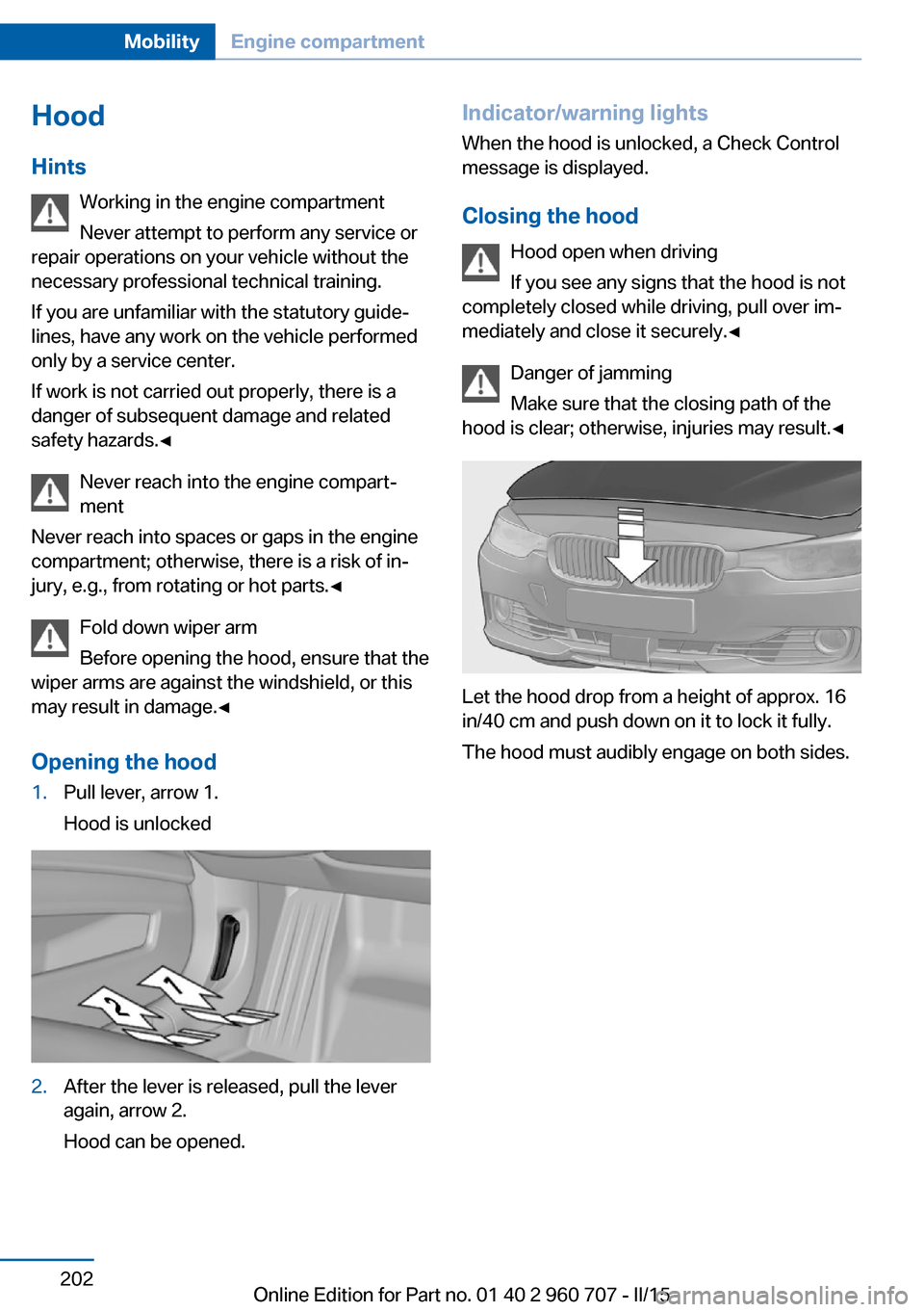
Opening the hood1.Pull lever, arrow 1.
Hood is unlocked2.After the lever is released, pull the lever
again, arrow 2.
Hood can be opened.Indicator/warning lights
When the hood is unlocked, a Check Control
message is displayed.
Closing the hood Hood open when driving
If you see any signs that the hood is not
completely closed while driving, pull over im‐
mediately and close it securely.◀
Danger of jamming
Make sure that the closing path of the
hood is clear; otherwise, injuries may result.◀
Let the hood drop from a height of approx. 16
in/40 cm and push down on it to lock it fully.
The hood must audibly engage on both sides.
Seite 202MobilityEngine compartment202
Online Edition for Part no. 01 40 2 960 707 - II/15
Page 210 of 249
CoolantVehicle features and optionsThis chapter describes all standard, country-
specific and optional features offered with the
series. It also describes features that are not
necessarily available in your car, e. g., due to
the selected options or country versions. This
also applies to safety-related functions and
systems. The respectively applicable country
provisions must be observed when using the
respective features and systems.
Hints Danger of burns from hot engine
Do not open the cooling system while
the engine is hot; otherwise, esliding coolant
may cause burns.◀
Suitable additives
Only use suitable additives; otherwise,
engine damage may occur. The additives are
harmful to your health.◀
Coolant consists of water and additives.
Not all commercially available additives are
suitable for the vehicle. Information about the
suitable additives are available from the service
center.
Coolant level
General information
Depending on the engine installation, the cool‐
ant reservoir is located on the right side or the
left side of the engine compartment.
Checking1.Let the engine cool.2.The coolant level is correct if it lies be‐
tween the minimum and maximum marks.The marks are on the side of the coolant
reservoir.SymbolMeaningMaximumMinimum
Adding
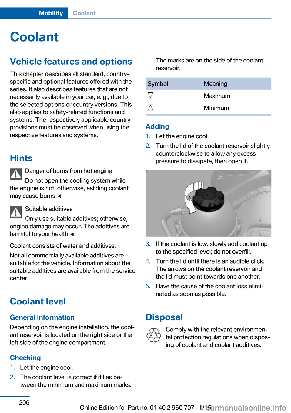
1.Let the engine cool.2.Turn the lid of the coolant reservoir slightly
counterclockwise to allow any excess
pressure to dissipate, then open it.3.If the coolant is low, slowly add coolant up
to the specified level; do not overfill.4.Turn the lid until there is an audible click.
The arrows on the coolant reservoir and
the lid must point towards one another.5.Have the cause of the coolant loss elimi‐
nated as soon as possible.
Disposal
Comply with the relevant environmen‐
tal protection regulations when dispos‐
ing of coolant and coolant additives.
Seite 206MobilityCoolant206
Online Edition for Part no. 01 40 2 960 707 - II/15
Page 219 of 249
These lights are made using LED technology.
Contact your service center in the event of a
malfunction.
Changing wheels
Hints When using run-flat tires or sealants, a tire
does not need to be changed immediately in
the event of pressure loss due to a flat tire.
Which is why no spare tire is available.
The tools for changing wheels are available as
accessories from your service center.
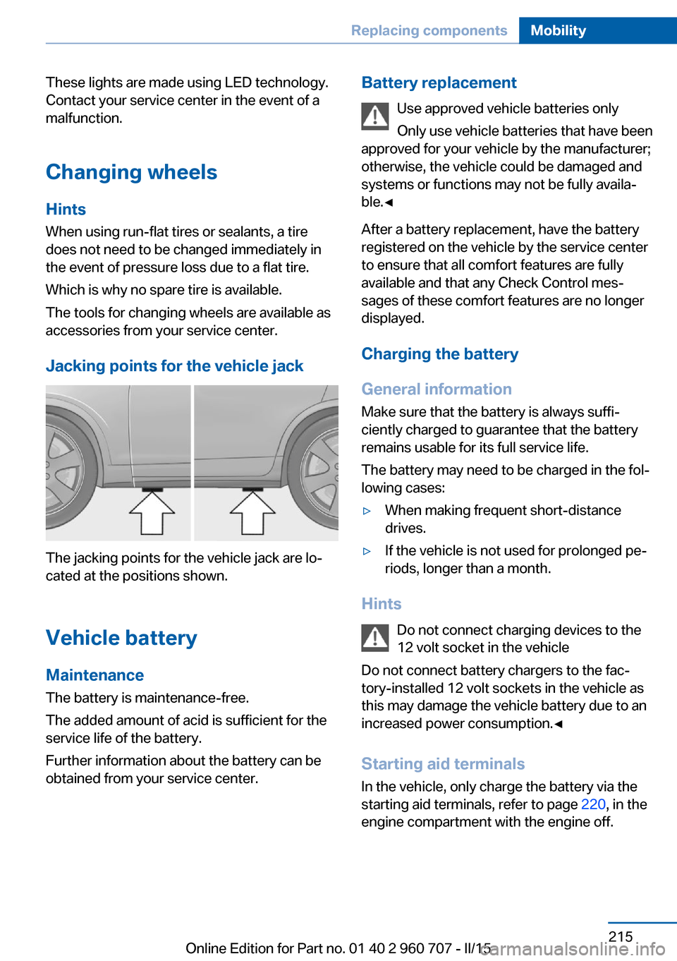
Jacking points for the vehicle jack
The jacking points for the vehicle jack are lo‐
cated at the positions shown.
Vehicle battery Maintenance
The battery is maintenance-free.
The added amount of acid is sufficient for the
service life of the battery.
Further information about the battery can be
obtained from your service center.
Battery replacement
Use approved vehicle batteries only
Only use vehicle batteries that have been
approved for your vehicle by the manufacturer;
otherwise, the vehicle could be damaged and
systems or functions may not be fully availa‐
ble.◀
After a battery replacement, have the battery registered on the vehicle by the service center
to ensure that all comfort features are fully
available and that any Check Control mes‐
sages of these comfort features are no longer
displayed.
Charging the battery
General information Make sure that the battery is always suffi‐
ciently charged to guarantee that the battery
remains usable for its full service life.
The battery may need to be charged in the fol‐
lowing cases:▷When making frequent short-distance
drives.▷If the vehicle is not used for prolonged pe‐
riods, longer than a month.
Hints
Do not connect charging devices to the
12 volt socket in the vehicle
Do not connect battery chargers to the fac‐
tory-installed 12 volt sockets in the vehicle as
this may damage the vehicle battery due to an
increased power consumption.◀
Starting aid terminals
In the vehicle, only charge the battery via the
starting aid terminals, refer to page 220, in the
engine compartment with the engine off.
Seite 215Replacing componentsMobility215
Online Edition for Part no. 01 40 2 960 707 - II/15
Page 220 of 249
Power failureAfter a temporary power loss, some equipment
needs to be newly initialized or individual set‐
tings updated, e. g.:▷Seat and mirror memory: store the posi‐
tions again.▷Time: update.▷Date: update.▷Glass sunroof and sliding visor: initialize
the system, refer to page 50.
Disposing of old batteries
Have old batteries disposed of by your
service center or bring them to a recy‐
cling center.
Maintain the battery in an upright position for
transport and storage. Secure the battery so
that it does not tip over during transport.
Fuses Hints Replacing fuses
Never attempt to repair a blown fuse and
do not replace a defective fuse with a substi‐
tute of another color or amperage rating; this
could lead to a circuit overload, ultimately re‐
sulting in a fire in the vehicle.◀
Plastic tweezers and information on the fuse
types and locations are stored in the fuse box
in the trunk.
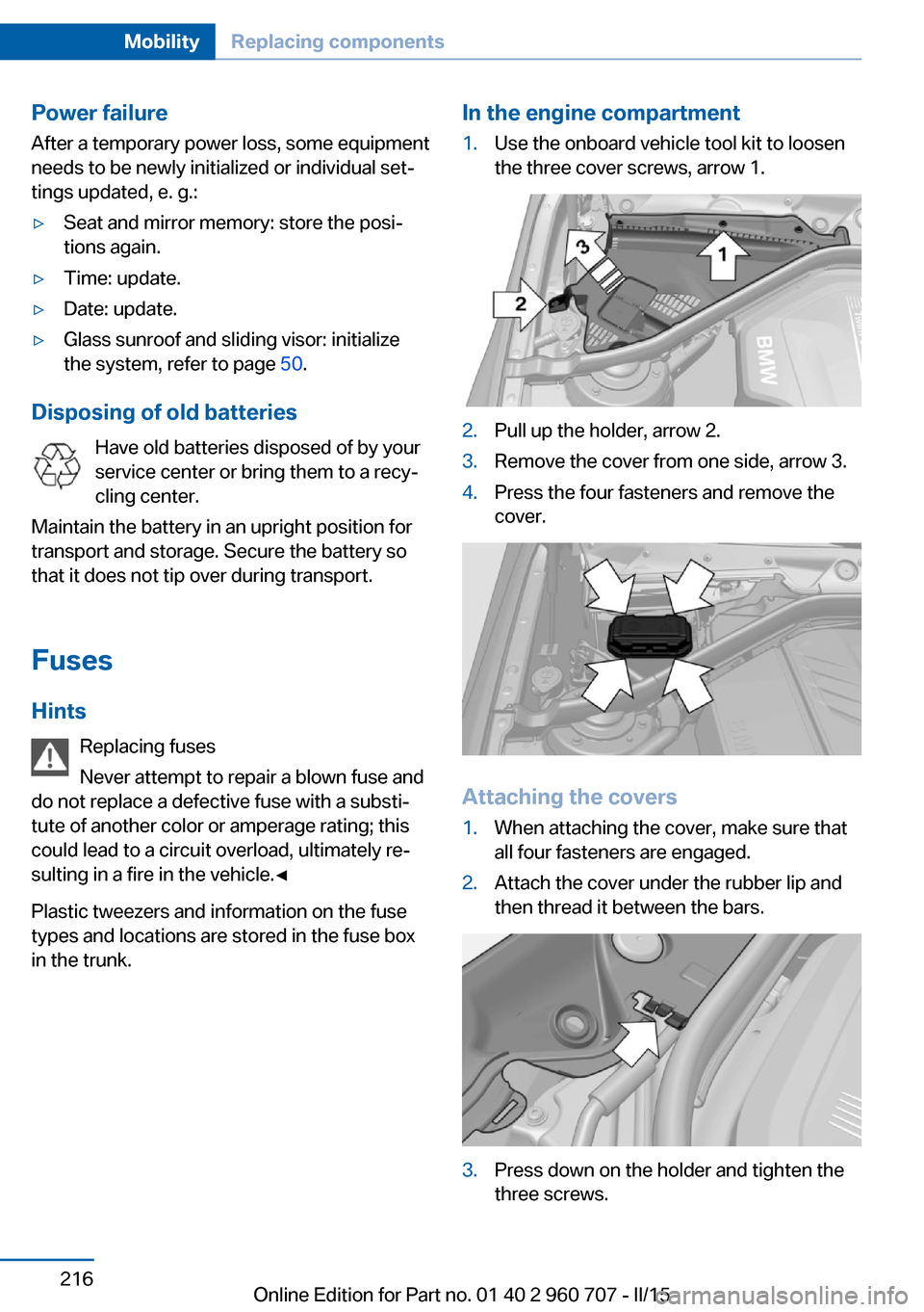
In the engine compartment1.Use the onboard vehicle tool kit to loosen
the three cover screws, arrow 1.2.Pull up the holder, arrow 2.3.Remove the cover from one side, arrow 3.4.Press the four fasteners and remove the
cover.
Attaching the covers
1.When attaching the cover, make sure that
all four fasteners are engaged.2.Attach the cover under the rubber lip and
then thread it between the bars.3.Press down on the holder and tighten the
three screws.Seite 216MobilityReplacing components216
Online Edition for Part no. 01 40 2 960 707 - II/15
Page 224 of 249
PreparationBodywork contact between vehicles
Make sure that there is no contact be‐
tween the bodywork of the two vehicles; other‐
wise, there is a danger of short circuits.◀1.Check whether the battery of the other ve‐
hicle has a voltage of 12 volts. This infor‐
mation can be found on the battery.2.Switch off the engine of the assisting vehi‐
cle.3.Switch off any electronic systems/power
consumers in both vehicles.
Starting aid terminals
Connecting order
Connect the jumper cables in the correct
order to prevent risk of injury from arcing.◀
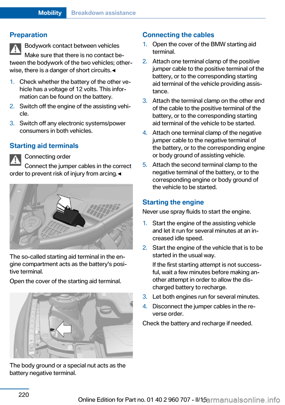
The so-called starting aid terminal in the en‐
gine compartment acts as the battery's posi‐
tive terminal.
Open the cover of the starting aid terminal.
The body ground or a special nut acts as the
battery negative terminal.
Connecting the cables1.Open the cover of the BMW starting aid
terminal.2.Attach one terminal clamp of the positive
jumper cable to the positive terminal of the
battery, or to the corresponding starting
aid terminal of the vehicle providing assis‐
tance.3.Attach the terminal clamp on the other end
of the cable to the positive terminal of the
battery, or to the corresponding starting
aid terminal of the vehicle to be started.4.Attach one terminal clamp of the negative
jumper cable to the negative terminal of
the battery, or to the corresponding engine
or body ground of assisting vehicle.5.Attach the second terminal clamp to the
negative terminal of the battery, or to the
corresponding engine or body ground of
the vehicle to be started.
Starting the engine
Never use spray fluids to start the engine.
1.Start the engine of the assisting vehicle
and let it run for several minutes at an in‐
creased idle speed.2.Start the engine of the vehicle that is to be
started in the usual way.
If the first starting attempt is not success‐
ful, wait a few minutes before making an‐
other attempt in order to allow the dis‐
charged battery to recharge.3.Let both engines run for several minutes.4.Disconnect the jumper cables in the re‐
verse order.
Check the battery and recharge if needed.
Seite 220MobilityBreakdown assistance220
Online Edition for Part no. 01 40 2 960 707 - II/15
Page 239 of 249
Bottle holder, refer to Cu‐pholders 163
Brake assistant 120
Brake discs, break-in 168
Brake force display 119
Brake lights, adaptive 119
Brake lights, brake force dis‐ play 119
Brake pads, break-in 168
Braking, hints 169
Breakdown assistance 218
Break-in 168
Brightness of Control Dis‐ play 91
Bulb replacement 209
Bulb replacement, front 210
Bulb replacement, LED head‐ lights 211
Bulb replacement, rear 212
Bulb replacement, xenon headlights 210
Bulbs and lights 209
Button, RES 128
Button, Start/Stop 65
Bypassing, refer to Jump- starting 219
C
California Proposition 65 Warning 7
Camera lenses, care 227
Camera, rearview cam‐ era 136
Camera, Side View 139
Camera, Top View 140
Can holder, refer to Cuphold‐ ers 163
Car battery 215
Car care products 225
Care, displays 227
Care, vehicle 225
Cargo 171
Cargo area 159
Cargo area, enlarging 159 Cargo area, storage compart‐
ments 163
Cargo cover 159
Cargo, securing 172
Cargo straps, securing cargo 172
Car key, refer to Remote con‐ trol 34
Carpet, care 227
Car wash 224
Catalytic converter, refer to Hot exhaust system 169
CBS Condition Based Serv‐ ice 207
CD/Multimedia, see user's manual for Navigation, En‐
tertainment and Communi‐
cation
Center armrest 162
Center console 16
Central locking system 40
Central screen, refer to Con‐ trol Display 18
Changes, technical, refer to Safety 7
Changing parts 209
Changing wheels 215
Changing wheels/tires 194
Chassis number, see vehicle identification number 9
Check Control 79
Checking the engine oil level electronically 203
Checking the oil level elec‐ tronically 203
Children, seating position 61
Children, transporting safely 61
Child restraint fixing sys‐ tem 61
Child restraint fixing system LATCH 63
Child restraint fixing systems, mounting 61
Child safety locks 64
Child seat, mounting 61 Child seats 61
Chrome parts, care 226
Cigarette lighter 157
Cleaning displays 227
Climate control 146, 148
Clock 83
Closing/opening via door lock 39
Closing/opening with remote control 37
Closing the tailgate with no- touch activation 44
Clothes hooks 163
Coasting 178
Coasting with engine decou‐ pled, coasting 178
Coasting with idling en‐ gine 178
Cockpit 14
Combination reel, refer to Turn signals 69
Combination switch, refer to Wiper system 70
Comfort Access 42
COMFORT program, Dy‐ namic Driving Control 123
Compartments in the doors 162
Compass 155
Compressor 196
Computer, refer to On-board computer 87
Condensation on win‐ dows 151
Condensation under the vehi‐ cle 170
Condition Based Service CBS 207
Configuring driving pro‐ gram 124
Confirmation signal 45
ConnectedDrive, see user's manual for Navigation, En‐
tertainment and Communi‐
cation
ConnectedDrive Services Seite 235Everything from A to ZReference235
Online Edition for Part no. 01 40 2 960 707 - II/15