rear BMW 428 COUPE 2015 User Guide
[x] Cancel search | Manufacturer: BMW, Model Year: 2015, Model line: 428 COUPE, Model: BMW 428 COUPE 2015Pages: 247, PDF Size: 5.26 MB
Page 62 of 247
Interior rearview mirror, manually
dimmable
Turn knob
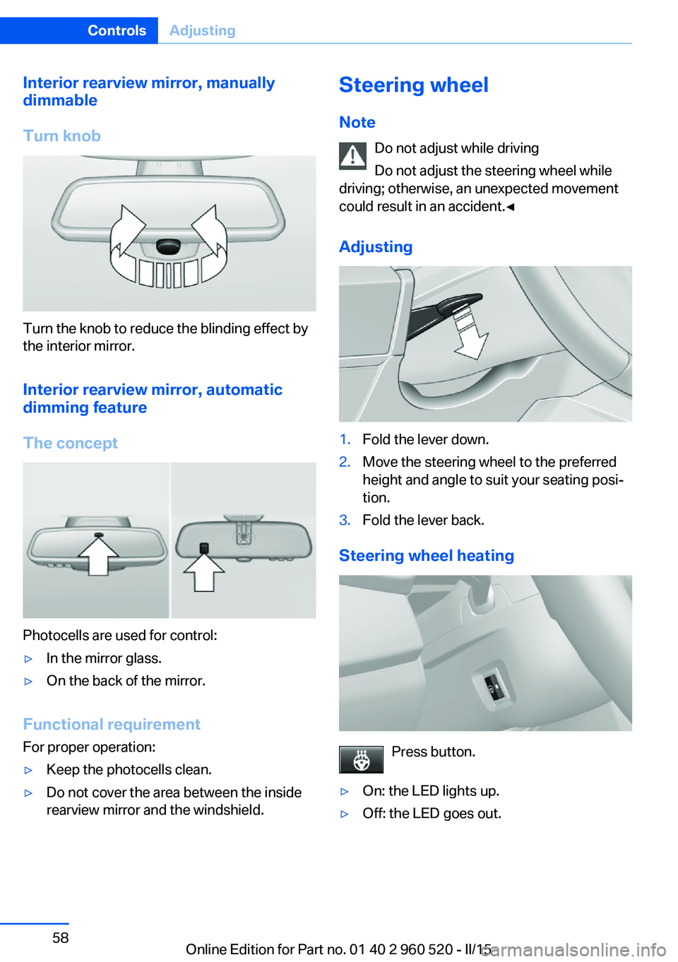
Turn the knob to reduce the blinding effect by
the interior mirror.
Interior rearview mirror, automaticdimming feature
The concept
Photocells are used for control:
▷In the mirror glass.▷On the back of the mirror.
Functional requirement For proper operation:
▷Keep the photocells clean.▷Do not cover the area between the inside
rearview mirror and the windshield.Steering wheel
Note Do not adjust while driving
Do not adjust the steering wheel while
driving; otherwise, an unexpected movement
could result in an accident.◀
Adjusting1.Fold the lever down.2.Move the steering wheel to the preferred
height and angle to suit your seating posi‐
tion.3.Fold the lever back.
Steering wheel heating
Press button.
▷On: the LED lights up.▷Off: the LED goes out.Seite 58ControlsAdjusting58
Online Edition for Part no. 01 40 2 960 520 - II/15
Page 63 of 247
Transporting children safelyVehicle features and optionsThis chapter describes all standard, country-
specific and optional features offered with the
series. It also describes features that are not
necessarily available in your car, e. g., due tothe selected options or country versions. This
also applies to safety-related functions and
systems. The respectively applicable country
provisions must be observed when using the
respective features and systems.
The right place for children
Note
Children in the vehicle
Do not leave children unattended in the
vehicle; otherwise, they could endanger them‐
selves and other persons, e.g., by opening the
doors.◀
Children should always be in the rear Accident research shows that the safest place
for children is in the back seat.
Transporting children in the rear
Only transport children younger than
13 years of age or shorter than 5 ft/150 cm in
the rear in child restraint systems provided in
accordance with the age, weight and size of
the child; otherwise, there is an increased risk
of injury in an accident.
Children 13 years of age or older must wear a
safety belt as soon as a suitable child restraint
system can no longer be used due to their age,
weight and size.◀
Children on the front passenger seat
Should it ever be necessary to use a child re‐
straint system in the front passenger seat,
make sure that the front, knee and side airbags
on the front passenger side are deactivated.
Automatic deactivation of front-seat passen‐
ger airbags, refer to page 98.Note
Deactivating the front-seat passenger
airbags
If a child restraint system is used in the front
passenger seat, deactivate the front-seat pas‐
senger airbags; otherwise, there is an in‐
creased risk of injury to the child when the air‐
bags are activated, even with a child restraint
system.◀
Installing child restraint
systems
Hints Manufacturer's information for child re‐straint systems
To select, mount and use child restraint sys‐
tems, observe the information provided by the
system manufacturer; otherwise, the protec‐
tive effect can be lost.◀
Ensuring the stability of the child seat
When installing child restraint systems,
make sure that the child seat is securely fas‐
tened to the backrest of the seat. Angle and
headrest of the backrest might need to be ad‐
justed or possibly be removed. Make sure that
all backrests are securely locked. Otherwise
the stability of the child seat can be affected,
and there is an increased risk of injury becauseSeite 59Transporting children safelyControls59
Online Edition for Part no. 01 40 2 960 520 - II/15
Page 64 of 247
of unexpected movement of the seat back‐
rest.◀
On the front passenger seat
Deactivating airbags Deactivating the front-seat passenger
airbags
If a child restraint system is used in the front
passenger seat, deactivate the front-seat pas‐
senger airbags; otherwise, there is an in‐
creased risk of injury to the child when the air‐
bags are activated, even with a child restraint
system.◀
After installing a child restraint system in the
front passenger seat, make sure that the front,
knee and side airbags on the front passenger
side are deactivated.
Deactivate the front-seat passenger airbags automatically, refer to page 98.
Seat position and height
Before installing a child restraint system, move
the front passenger seat as far back as possi‐
ble and adjust its height to the highest and
thus best possible position for the belt and to
offer optimal protection in the event of an acci‐
dent.
If the upper anchorage of the safety belt is lo‐
cated in front of the belt guide of the child seat,
move the passenger seat carefully forward un‐
til the best possible belt guide position is
reached.
Backrest width Backrest width for the child seat
Before installing a child restraint system
in the front passenger seat, the backrest width
must be opened completely. Do not changethe adjustment after this; otherwise, the stabil‐
ity of the child seat will be reduced.◀
Adjustable backrest width: before installing a
child restraint system in the front passenger
seat, open the backrest width completely. Do
not change the backrest width again and do
not call up a memory position.
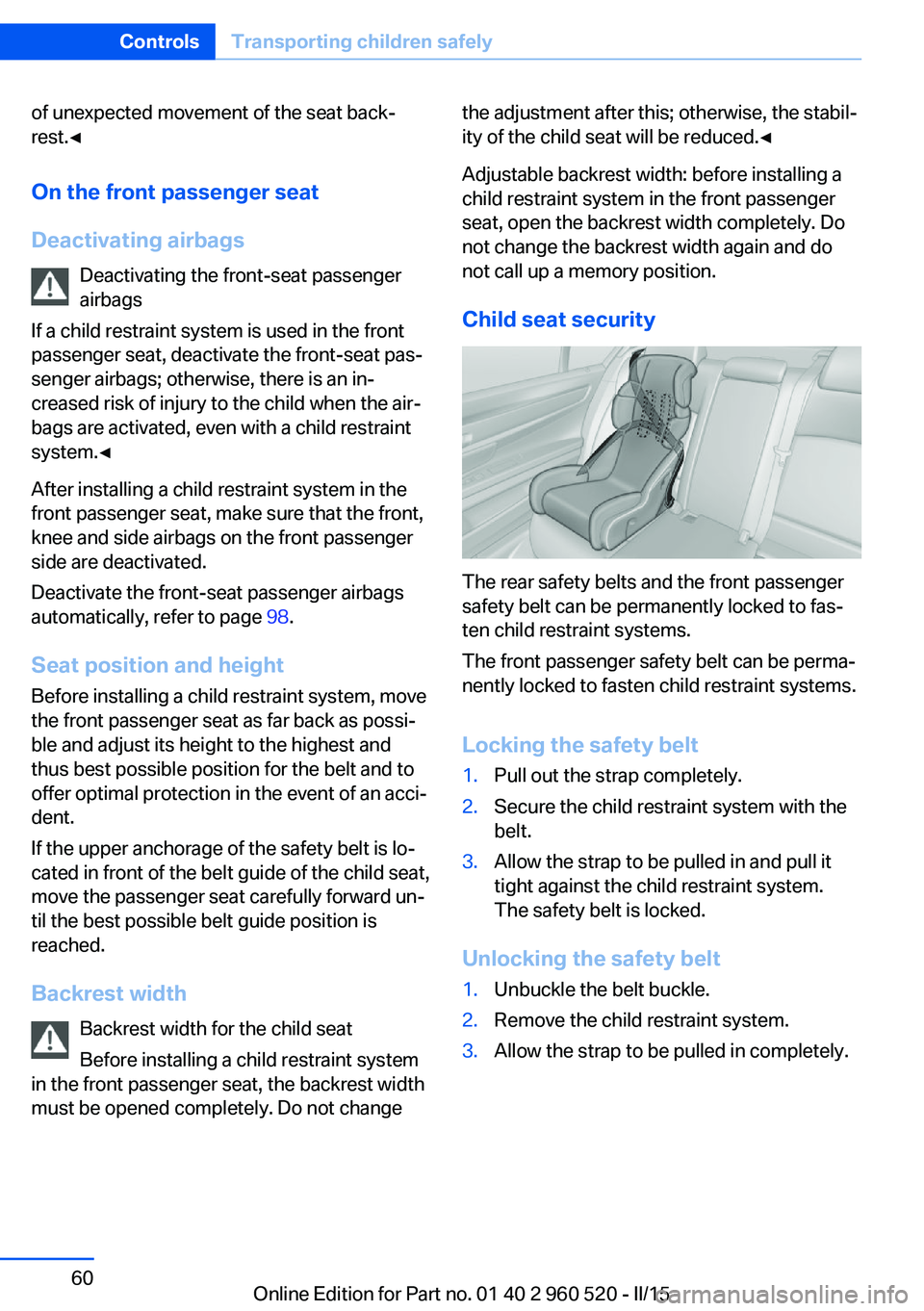
Child seat security
The rear safety belts and the front passenger
safety belt can be permanently locked to fas‐
ten child restraint systems.
The front passenger safety belt can be perma‐
nently locked to fasten child restraint systems.
Locking the safety belt
1.Pull out the strap completely.2.Secure the child restraint system with the
belt.3.Allow the strap to be pulled in and pull it
tight against the child restraint system.
The safety belt is locked.
Unlocking the safety belt
1.Unbuckle the belt buckle.2.Remove the child restraint system.3.Allow the strap to be pulled in completely.Seite 60ControlsTransporting children safely60
Online Edition for Part no. 01 40 2 960 520 - II/15
Page 65 of 247
LATCH child restraint systemLATCH: Lower Anchors and Tether for Chil‐
dren.
Note Follow manufacturer's information for
LATCH child restraint systems
To mount and use the LATCH child restraint
systems, observe the operating and safety in‐
formation from the system manufacturer; oth‐
erwise, the level of protection may be re‐
duced.◀
Mounts for the lower LATCH anchors
The lower anchors may be used to attach the
CRS to the vehicle seat up to a combined child
and CRS weight of 65 lb/30 kg when the child
is restrained by the internal harnesses.
Note Properly engage the lower LATCH an‐
chors
Make sure that the lower LATCH anchors have
properly engaged and that the child restraint
system is resting snugly against the backrest;
otherwise, the degree of protection may be re‐
duced.◀
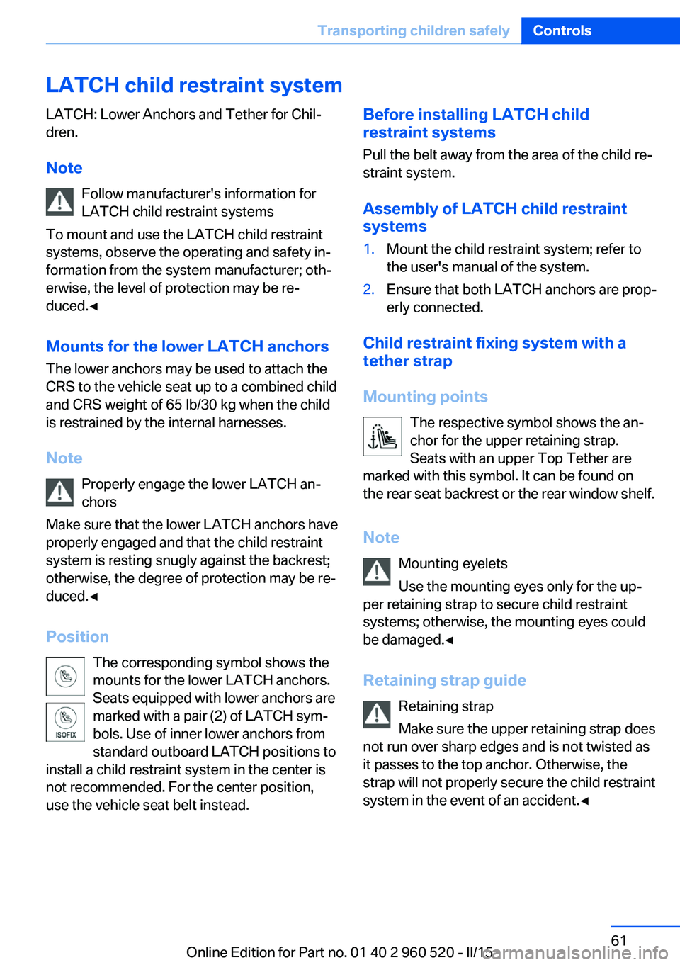
Position The corresponding symbol shows the
mounts for the lower LATCH anchors.
Seats equipped with lower anchors are
marked with a pair (2) of LATCH sym‐
bols. Use of inner lower anchors from
standard outboard LATCH positions to
install a child restraint system in the center is
not recommended. For the center position,
use the vehicle seat belt instead.Before installing LATCH child
restraint systems
Pull the belt away from the area of the child re‐
straint system.
Assembly of LATCH child restraint
systems1.Mount the child restraint system; refer to
the user's manual of the system.2.Ensure that both LATCH anchors are prop‐
erly connected.
Child restraint fixing system with a
tether strap
Mounting points The respective symbol shows the an‐
chor for the upper retaining strap.
Seats with an upper Top Tether are
marked with this symbol. It can be found on
the rear seat backrest or the rear window shelf.
Note Mounting eyelets
Use the mounting eyes only for the up‐
per retaining strap to secure child restraint
systems; otherwise, the mounting eyes could
be damaged.◀
Retaining strap guide Retaining strap
Make sure the upper retaining strap does
not run over sharp edges and is not twisted as
it passes to the top anchor. Otherwise, the
strap will not properly secure the child restraint
system in the event of an accident.◀
Seite 61Transporting children safelyControls61
Online Edition for Part no. 01 40 2 960 520 - II/15
Page 66 of 247
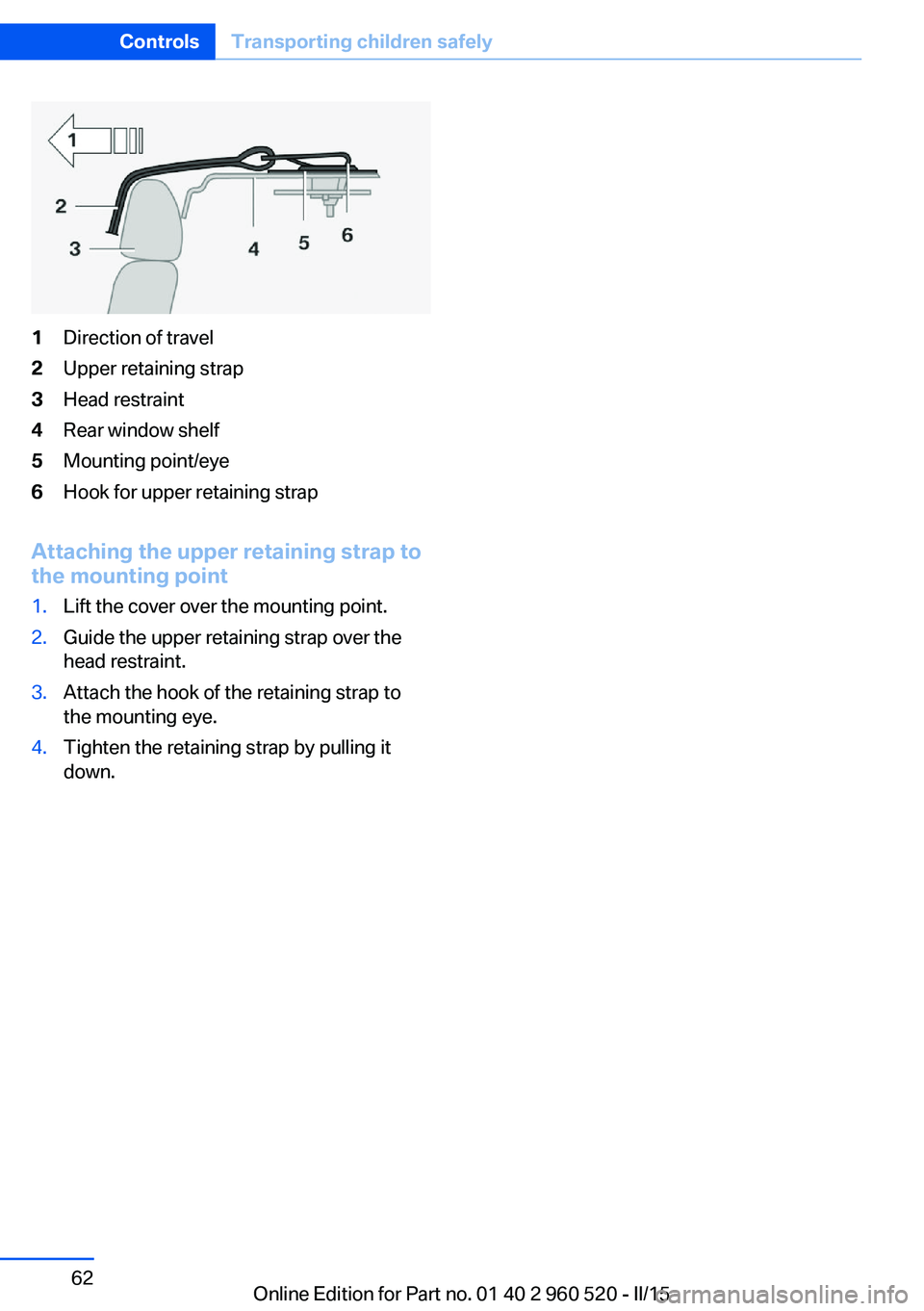
1Direction of travel2Upper retaining strap3Head restraint4Rear window shelf5Mounting point/eye6Hook for upper retaining strap
Attaching the upper retaining strap to
the mounting point
1.Lift the cover over the mounting point.2.Guide the upper retaining strap over the
head restraint.3.Attach the hook of the retaining strap to
the mounting eye.4.Tighten the retaining strap by pulling it
down.Seite 62ControlsTransporting children safely62
Online Edition for Part no. 01 40 2 960 520 - II/15
Page 71 of 247
▷LED goes out: Auto Start/Stop function is
activated.
Switching off the vehicle during an
automatic engine stop
During an automatic engine stop, the vehicle
can be switched off permanently, e. g., when
leaving it.
1.Press the Start/Stop button. The ignition is
switched off. The Auto Start/Stop function
is deactivated.
Selector lever position P is engaged auto‐
matically.2.Set the parking brake.
Engine start as usual via Start/Stop button.
Automatic deactivation
In certain situations, Auto Start/Stop function
is deactivated automatically for safety reasons
as if the driver were absent.
Malfunction
The Auto Start/Stop function no longer
switches off the engine automatically. A Check
Control message is displayed. It is possible to
continue driving. Have the system checked.
Parking brake Applying
The lever automatically engages after being
pulled up.
The indicator lamp lights up red. The
parking brake is set.
Lower lamp: indicator lamp in Canadian
models
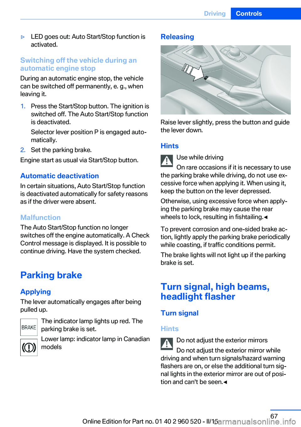
Releasing
Raise lever slightly, press the button and guide
the lever down.
Hints Use while driving
On rare occasions if it is necessary to use
the parking brake while driving, do not use ex‐
cessive force when applying it. When using it,
keep the button on the lever depressed.
Otherwise, using excessive force when apply‐
ing the parking brake may cause the rear
wheels to lock, resulting in fishtailing.◀
To prevent corrosion and one-sided brake ac‐
tion, lightly apply the parking brake periodically
while coasting, if traffic conditions permit.
The brake lights will not light up if the parking
brake is set.
Turn signal, high beams,
headlight flasher
Turn signal
Hints Do not adjust the exterior mirrors
Do not adjust the exterior mirror while
driving and when turn signals/hazard warning
flashers are on, or else the additional turn sig‐
nal lights in the exterior mirror are out of posi‐
tion and can't be seen.◀
Seite 67DrivingControls67
Online Edition for Part no. 01 40 2 960 520 - II/15
Page 73 of 247
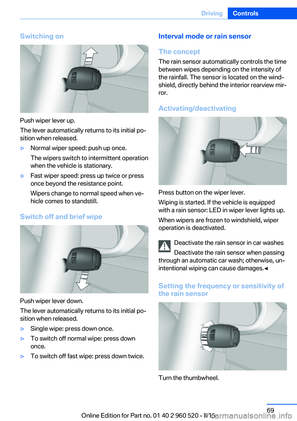
Switching on
Push wiper lever up.
The lever automatically returns to its initial po‐
sition when released.
▷Normal wiper speed: push up once.
The wipers switch to intermittent operation
when the vehicle is stationary.▷Fast wiper speed: press up twice or press
once beyond the resistance point.
Wipers change to normal speed when ve‐
hicle comes to standstill.
Switch off and brief wipe
Push wiper lever down.
The lever automatically returns to its initial po‐
sition when released.
▷Single wipe: press down once.▷To switch off normal wipe: press down
once.▷To switch off fast wipe: press down twice.Interval mode or rain sensor
The concept The rain sensor automatically controls the time
between wipes depending on the intensity of the rainfall. The sensor is located on the wind‐
shield, directly behind the interior rearview mir‐
ror.
Activating/deactivating
Press button on the wiper lever.
Wiping is started. If the vehicle is equipped
with a rain sensor: LED in wiper lever lights up.
When wipers are frozen to windshield, wiper
operation is deactivated.
Deactivate the rain sensor in car washes
Deactivate the rain sensor when passing
through an automatic car wash; otherwise, un‐
intentional wiping can cause damages.◀
Setting the frequency or sensitivity of
the rain sensor
Turn the thumbwheel.
Seite 69DrivingControls69
Online Edition for Part no. 01 40 2 960 520 - II/15
Page 77 of 247
Once maximum engine speed is attained, M/S
manual mode is automatically upshifted as
needed.
Switching to manual mode▷To shift down: press the selector lever for‐
ward.▷To shift up: pull the selector lever rear‐
wards.
Gears will only be shifted at appropriate engine
and road speeds, for example downshifting is
not possible if the engine speed is too high.
The selected gear is briefly displayed in the in‐
strument cluster, followed by the currently se‐
lected gear.
Steptronic Sport transmission:
prevent automatic upshifting in M/S
manual mode
The Steptronic Sport transmission does not
automatically upshift in M/S manual mode
once the maximum speed is reached, if one of
the following conditions is met:
▷DSC deactivated.▷TRACTION activated.▷SPORT+ activated.
In addition, the kickdown is deactivated.
With the respective transmission version, the
lowest possible gear can be selected by simul‐
taneously operating the kickdown and the left
shift paddle. However, this effect is not pro‐
duced via the shift paddles when switching
briefly from D to manual mode.
Ending the sport program/manual
mode
Push the selector lever to the right.
D is displayed in the instrument cluster.
Shift paddles
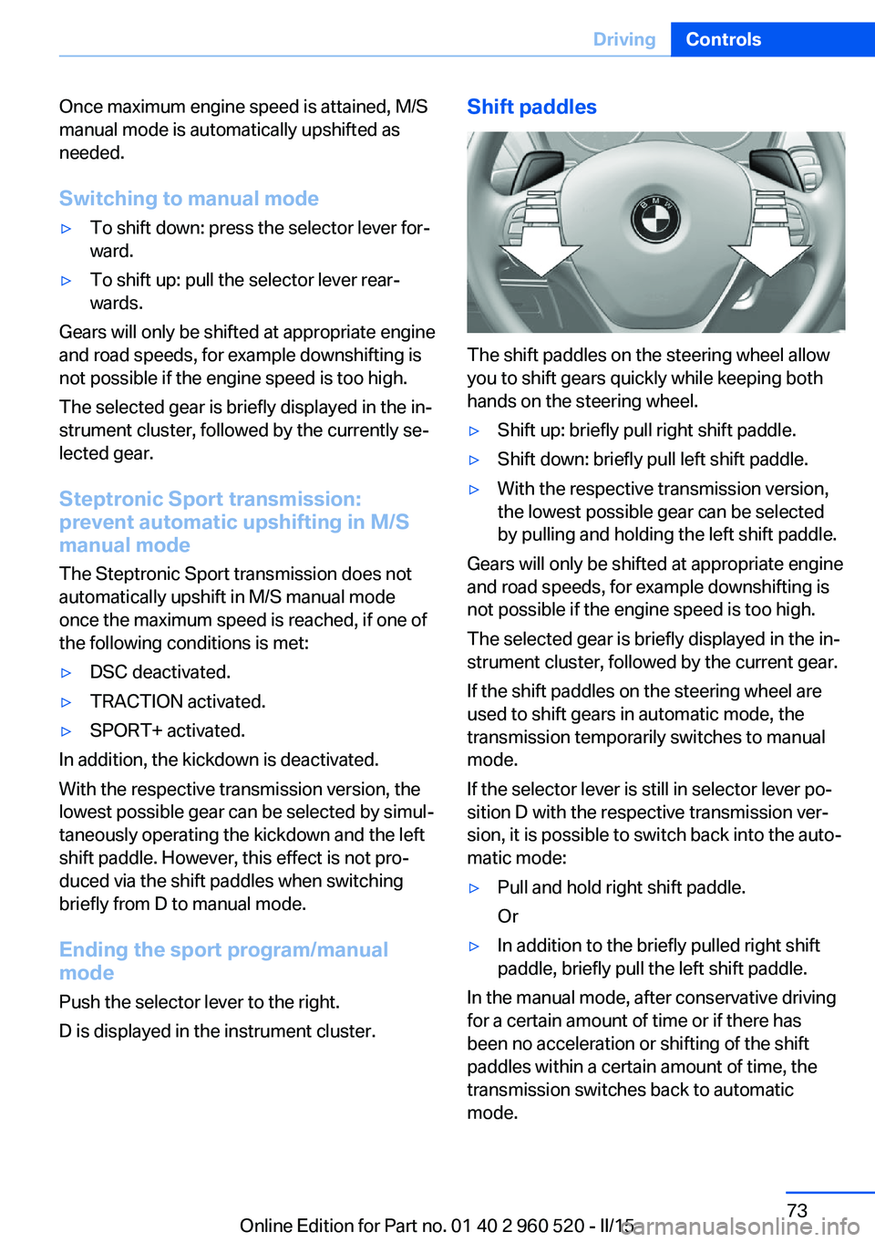
The shift paddles on the steering wheel allow
you to shift gears quickly while keeping both
hands on the steering wheel.
▷Shift up: briefly pull right shift paddle.▷Shift down: briefly pull left shift paddle.▷With the respective transmission version,
the lowest possible gear can be selected
by pulling and holding the left shift paddle.
Gears will only be shifted at appropriate engine
and road speeds, for example downshifting is
not possible if the engine speed is too high.
The selected gear is briefly displayed in the in‐
strument cluster, followed by the current gear.
If the shift paddles on the steering wheel are
used to shift gears in automatic mode, the
transmission temporarily switches to manual
mode.
If the selector lever is still in selector lever po‐
sition D with the respective transmission ver‐
sion, it is possible to switch back into the auto‐
matic mode:
▷Pull and hold right shift paddle.
Or▷In addition to the briefly pulled right shift
paddle, briefly pull the left shift paddle.
In the manual mode, after conservative driving
for a certain amount of time or if there has
been no acceleration or shifting of the shift
paddles within a certain amount of time, the
transmission switches back to automatic
mode.
Seite 73DrivingControls73
Online Edition for Part no. 01 40 2 960 520 - II/15
Page 88 of 247
Speed limit detection
The concept
Speed limit detection
Speed limit detection uses a symbol in the
shape of a traffic sign to display the currently
detected speed limit. The camera in the area of
the interior rearview mirror detects traffic signs
at the edge of the road as well as variable over‐
head sign posts. Traffic signs with extra sym‐
bols for wet road conditions, etc. are also de‐
tected and compared with the vehicle's
onboard data, such as for the rain sensor, and
will be displayed depending on the situation.
The system takes into account the information
stored in the navigation system and also dis‐
plays speed limits present on routes without
signs.
Hints Personal judgment
The system cannot serve as a substitute
for the driver's personal judgment of the traffic
situation.
The system assists the driver and does not re‐
place the human eye.◀
At a glance
Camera
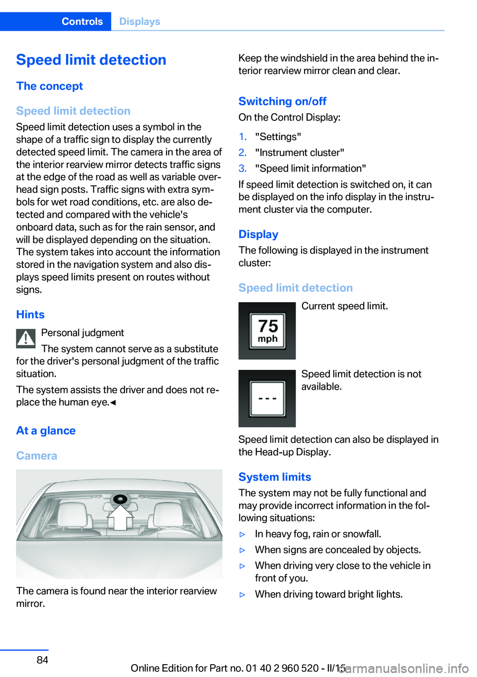
The camera is found near the interior rearview
mirror.
Keep the windshield in the area behind the in‐
terior rearview mirror clean and clear.
Switching on/offOn the Control Display:1."Settings"2."Instrument cluster"3."Speed limit information"
If speed limit detection is switched on, it can
be displayed on the info display in the instru‐
ment cluster via the computer.
Display The following is displayed in the instrument
cluster:
Speed limit detection Current speed limit.
Speed limit detection is not available.
Speed limit detection can also be displayed in
the Head-up Display.
System limits
The system may not be fully functional and
may provide incorrect information in the fol‐
lowing situations:
▷In heavy fog, rain or snowfall.▷When signs are concealed by objects.▷When driving very close to the vehicle in
front of you.▷When driving toward bright lights.Seite 84ControlsDisplays84
Online Edition for Part no. 01 40 2 960 520 - II/15
Page 89 of 247
▷When the windshield behind the interior
rearview mirror is fogged over, dirty or cov‐
ered by a sticker, etc.▷In the event of incorrect detection by the
camera.▷If the speed limits stored in the navigation
system are incorrect.▷In areas not covered by the navigation sys‐
tem.▷When roads differ from the navigation,
such as due to changes in road routing.▷When passing buses or trucks with a
speed sticker.▷If the traffic signs are non-conforming.▷During calibration of the camera immedi‐
ately after vehicle shipment.
Selection lists in the
instrument cluster
The concept Depending on your vehicle's optional features,
the following can be displayed or operated us‐
ing the buttons and the thumbwheel on the
steering wheel as well as the displays in the in‐
strument cluster and the Head-up Display:
▷Current audio source.▷Redial phone feature.▷Turn on voice activation system.
It also displays programs of the Driving Dy‐
namics Control.
Display
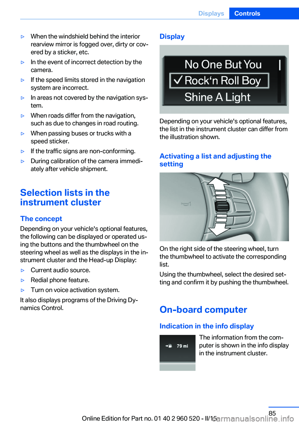
Depending on your vehicle's optional features,
the list in the instrument cluster can differ from
the illustration shown.
Activating a list and adjusting the
setting
On the right side of the steering wheel, turn
the thumbwheel to activate the corresponding
list.
Using the thumbwheel, select the desired set‐
ting and confirm it by pushing the thumbwheel.
On-board computer
Indication in the info display The information from the com‐
puter is shown in the info display
in the instrument cluster.
Seite 85DisplaysControls85
Online Edition for Part no. 01 40 2 960 520 - II/15