instrument cluster BMW 428I CONVERTIBLE 2016 User Guide
[x] Cancel search | Manufacturer: BMW, Model Year: 2016, Model line: 428I CONVERTIBLE, Model: BMW 428I CONVERTIBLE 2016Pages: 247, PDF Size: 5.22 MB
Page 83 of 247

For more information, see Tire Pressure Moni‚Äź
tor, refer to page 100.
Steering system Steering system in some cases defec‚Äź
tive.
Have the steering system checked by
the service center.
Engine functions Have the vehicle checked by the serv‚Äźice center.
For additional information, refer to On-
board Diagnostics socket, refer to page 206.
Lane departure warning System is switched on and under cer‚Äź
tain circumstances warns if a detected
lane is left without flashing beforehand.
For additional information, refer to Lane depar‚Äź
ture warning, refer to page 114.
Green lights Turn signal Turn signal on.
Unusually rapid flashing of the indicator
lamp indicates that a turn signal bulb
has failed.
For additional information, refer to Turn signal,
refer to page 68.
Parking lights, headlight control Parking lights or headlights are acti‚Äź
vated.
For additional information, refer to
Parking lights/low beams, headlight control, re‚Äź
fer to page 91.Front fog lights
Front fog lights are activated.
For additional information, refer to
Front fog lights, refer to page 94.
High-beam Assistant High-beam Assistant is switched on.
High beams are activated and off auto‚Äź
matically as a function of the traffic sit‚Äź
uation.
For additional information, refer to High-beam
Assistant, refer to page 93.
Cruise control The system is switched on. It maintains
the speed that was set using the con‚Äź
trol elements on the steering wheel.
Blue lights
High beams High beams are activated.
For additional information, refer to High
beams, refer to page 69.
General lamps
Check Control At least one Check Control message is
displayed or is stored. The symbol is
shown in the display of the instrument
cluster.
Text messagesText messages in combination with a symbol
in the instrument cluster explain a Check Con‚Äź trol message and the meaning of the indicator
and warning lights.Seite 79DisplaysControls79
Online Edition for Part no. 01 40 2 960 547 - II/15
Page 85 of 247

middle or in the left half of
the temperature display.‚Ė∑Hot engine: the pointer is at the high end of
the temperature range. A Check Control
message is also displayed.
Coolant temperature
If the coolant along with the engine becomes
too hot, a Check Control message is displayed.
Check the coolant level, refer to page 204.
Odometer and trip odometer Display
‚Ė∑Odometer, arrow 1.‚Ė∑Trip odometer, arrow 2.
Show/reset kilometers Press the knob.
‚Ė∑When the ignition is
switched off, the time, the
external temperature and
the odometer are displayed.‚Ė∑When the ignition is switched on, the trip
odometer is reset.
External temperature
If the indicator drops to
+37 ‚ĄČ/+3 ‚ĄÉ or lower, a signal
sounds.
A Check Control message is displayed.
There is an increased risk of ice on roads.
Ice on roads
Even at temperatures above
+37 ‚ĄČ/+3 ‚ĄÉ, roads might be icy.
Therefore, drive carefully on bridges and
shaded roads, e.g., to avoid the increased risk
of an accident.‚óÄ
Time The time is displayed at the bot‚Äź
tom of the instrument cluster.
Setting the time and time for‚Äź
mat, refer to page 88.
Date The date is displayed in the
computer.
Setting the date and date for‚Äź
mat, refer to page 88.
Range
Display With a low remaining range:‚Ė∑A Check Control message is
displayed briefly.‚Ė∑The remaining range is
shown on the on-board co‚Äź
mupter.‚Ė∑With a dynamic driving style - e.g., taking
curves aggressively - engine operation
might vary.
The Check Control message appears continu‚Äź
ously below a range of approx. 30 miles/50 km.
Refuel promptly
Refuel no later than at a range of
30 miles/50 km or engine operation might fail
and damage might occur.‚óÄ
Seite 81DisplaysControls81
Online Edition for Part no. 01 40 2 960 547 - II/15
Page 86 of 247
Displaying the cruising rangeDepending on your vehicle's optional features,
the range can also be displayed as bar in the
instrument cluster.1."Settings"2."Instrument cluster"3."Additional indicators"
Current fuel consumption
Instrument cluster Displays the current fuel con‚Äź
sumption. Check whether you
are currently driving in an effi‚Äź
cient and environmentally-
friendly manner.
Instrum. cluster with enhanced
features
Displays the current fuel con‚Äź
sumption. Check whether you
are currently driving in an effi‚Äź
cient and environmentally-
friendly manner.
Displaying the current fuel
consumption
1."Settings"2."Instrument cluster"3."Additional indicators"
The bar display for the current fuel consump‚Äź
tion is displayed in the instrument cluster.
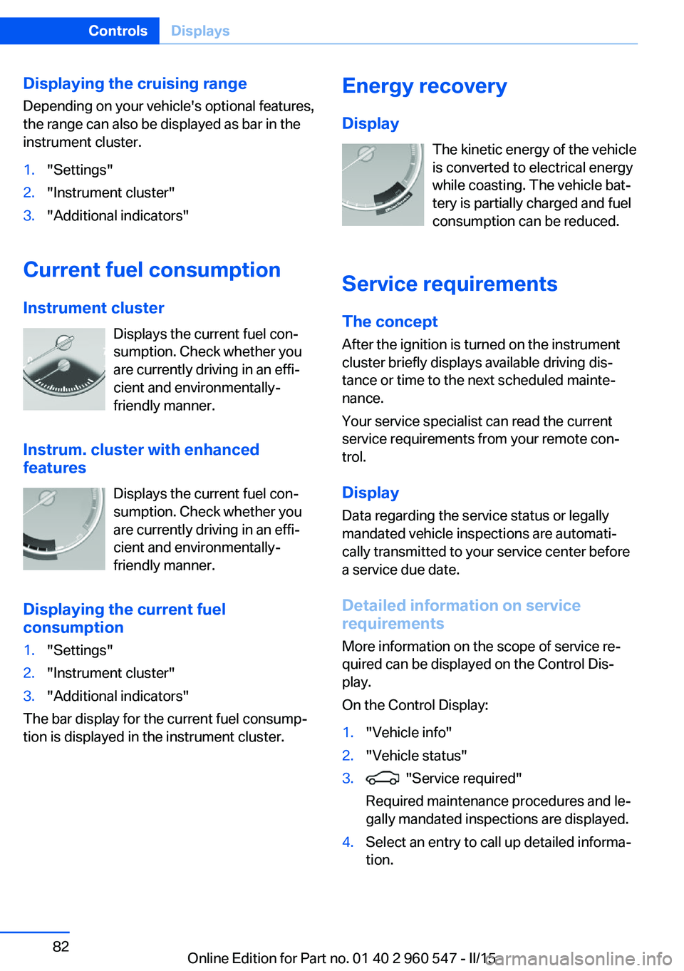
Energy recovery
Display The kinetic energy of the vehicle
is converted to electrical energy while coasting. The vehicle bat‚Äź
tery is partially charged and fuel
consumption can be reduced.
Service requirements The concept
After the ignition is turned on the instrument
cluster briefly displays available driving dis‚Äź
tance or time to the next scheduled mainte‚Äź
nance.
Your service specialist can read the current
service requirements from your remote con‚Äź
trol.
Display
Data regarding the service status or legally
mandated vehicle inspections are automati‚Äź
cally transmitted to your service center before
a service due date.
Detailed information on service
requirements
More information on the scope of service re‚Äź
quired can be displayed on the Control Dis‚Äź
play.
On the Control Display:1."Vehicle info"2."Vehicle status"3. "Service required"
Required maintenance procedures and le‚Äź
gally mandated inspections are displayed.4.Select an entry to call up detailed informa‚Äź
tion.Seite 82ControlsDisplays82
Online Edition for Part no. 01 40 2 960 547 - II/15
Page 87 of 247

SymbolsSym‚Äź
bolsDescriptionNo service is currently required.The deadline for scheduled mainte‚Äź
nance or a legally mandated inspec‚Äź
tion is approaching.The service deadline has already
passed.
Entering appointment dates
Enter the dates for the required inspections.
Make sure that the vehicle's date and time are
set correctly.
On the Control Display:
1."Vehicle info"2."Vehicle status"3. "Service required"4."§ Vehicle inspection"5."Date:"6.Adjust the settings.7.Confirm.
The entered date is stored.
Automatic Service Request
Data regarding the service status or legally
mandated vehicle inspections are automati‚Äź
cally transmitted to your service center before
a service due date.
You can check when your service center was
notified.
On the Control Display:
1."Vehicle info"2."Vehicle status"3.Open "Options".4."Last Service Request"Gear shift indicator
The conceptThe system recommends the most fuel effi‚Äź
cient gear for the current driving situation.
Depending on the vehicle's features and coun‚Äź
try version of the vehicle, the gear shift indica‚Äź
tor is active in the manual mode of the Step‚Äź
tronic transmission and with manual
transmission.
Suggestions to shift gear up or down are dis‚Äź
played in the instrument cluster.
Steptronic transmission: displaysExampleDescriptionFuel efficient gear is set.Shift into fuel efficient gear.
Speed limit detection
The concept
Speed limit detection
Speed limit detection uses a symbol in the
shape of a traffic sign to display the currently
detected speed limit. The camera in the area of
the interior rearview mirror detects traffic signs
at the edge of the road as well as variable over‚Äź
head sign posts. Traffic signs with extra sym‚Äź
bols for wet road conditions, etc. are also de‚Äź
tected and compared with the vehicle's
onboard data, such as for the rain sensor, and
will be displayed depending on the situation.
The system takes into account the information
stored in the navigation system and also dis‚Äź
plays speed limits present on routes without
signs.
Seite 83DisplaysControls83
Online Edition for Part no. 01 40 2 960 547 - II/15
Page 88 of 247

HintsPersonal judgment
The system cannot serve as a substitute
for the driver's personal judgment of the traffic
situation.
The system assists the driver and does not re‚Äź
place the human eye.‚óÄ
At a glance
Camera
The camera is found near the interior rearview
mirror.
Keep the windshield in the area behind the in‚Äź
terior rearview mirror clean and clear.
Switching on/offOn the Control Display:
1."Settings"2."Instrument cluster"3."Speed limit information"
If speed limit detection is switched on, it can
be displayed on the info display in the instru‚Äź
ment cluster via the computer.
Display The following is displayed in the instrument
cluster:
Speed limit detection
Current speed limit.
Speed limit detection is not
available.
Speed limit detection can also be displayed in
the Head-up Display.
System limits
The system may not be fully functional and
may provide incorrect information in the fol‚Äź
lowing situations:‚Ė∑In heavy fog, rain or snowfall.‚Ė∑When signs are concealed by objects.‚Ė∑When driving very close to the vehicle in
front of you.‚Ė∑When driving toward bright lights.‚Ė∑When the windshield behind the interior
rearview mirror is fogged over, dirty or cov‚Äź
ered by a sticker, etc.‚Ė∑In the event of incorrect detection by the
camera.‚Ė∑If the speed limits stored in the navigation
system are incorrect.‚Ė∑In areas not covered by the navigation sys‚Äź
tem.‚Ė∑When roads differ from the navigation,
such as due to changes in road routing.‚Ė∑When passing buses or trucks with a
speed sticker.‚Ė∑If the traffic signs are non-conforming.‚Ė∑During calibration of the camera immedi‚Äź
ately after vehicle shipment.Seite 84ControlsDisplays84
Online Edition for Part no. 01 40 2 960 547 - II/15
Page 89 of 247

Selection lists in the
instrument cluster
The concept Depending on your vehicle's optional features,
the following can be displayed or operated us‚Äź
ing the buttons and the thumbwheel on the
steering wheel as well as the displays in the in‚Äź
strument cluster and the Head-up Display:‚Ė∑Current audio source.‚Ė∑Redial phone feature.‚Ė∑Turn on voice activation system.
It also displays programs of the Driving Dy‚Äź
namics Control.
Display
Depending on your vehicle's optional features,
the list in the instrument cluster can differ from
the illustration shown.
Activating a list and adjusting the
setting
On the right side of the steering wheel, turn
the thumbwheel to activate the corresponding
list.
Using the thumbwheel, select the desired set‚Äź
ting and confirm it by pushing the thumbwheel.
On-board computer
Indication in the info display The information from the com‚Äź
puter is shown in the info display
in the instrument cluster.
Calling up information on the info
display
Press the onboard computer button on the
turn signal lever.
Information is displayed in the info display of
the instrument cluster.
Seite 85DisplaysControls85
Online Edition for Part no. 01 40 2 960 547 - II/15
Page 90 of 247

Information at a glanceRepeatedly pressing the button on the turn
signal lever calls up the following information in
the info display:‚Ė∑Range.‚Ė∑Average consumption, fuel.‚Ė∑Average consumption, fuel.‚Ė∑Average speed.‚Ė∑Date.‚Ė∑Speed limit detection.‚Ė∑Time of arrival.
When destination guidance is activated in
the navigation system.‚Ė∑Distance to destination.
When destination guidance is activated in
the navigation system.‚Ė∑ECO PRO bonus range.
Adjusting the info display
Depending on the vehicle equipment version,
you can select what information from the com‚Äź
puter is to be displayed on the info display of
the instrument cluster.
On the Control Display:
1."Settings"2."Instrument cluster"3.Select the desired displays.
Information in detail
Range
Displays the estimated cruising range available
with the remaining fuel.
It is calculated based on your driving style over
the last 20 miles/30 km.
If there is only enough fuel left for less than
45 miles/80 km, the color of the display
changes.
Average fuel consumption
The average fuel consumption is calculated for
the period while the engine is running.
The average fuel consumption is calculated for
the distance traveled since the last reset by the
on-board comupter.
Average speed
Periods in which the vehicle is parked with the
engine manually stopped are not included in
the calculation of the average speed.
Resetting average values Press and hold the onboard computer button
on the turn signal lever.
Distance to destination
The distance remaining to the destination is
displayed if a destination is entered in the navi‚Äź
gation system before the trip is started.
The distance to the destination is adopted au‚Äź
tomatically.
Time of arrival The estimated time of arrival is
displayed if a destination is en‚Äź
tered in the navigation system
before the trip is started.
The time must be correctly set.
Speed limit detection
Description of the speed limit detection, refer
to page 83, function.
Trip computer
The vehicle features two types of board com‚Äź
puters.‚Ė∑"Onboard info": the values can be reset as
often as necessary.‚Ė∑"Trip computer": the values provide an
overview of the current trip.Seite 86ControlsDisplays86
Online Edition for Part no. 01 40 2 960 547 - II/15
Page 93 of 247

Units of measure
Setting the units of measure
To set the units for fuel consumption, route/
distance and temperature:1."Settings"2."Language/Units"3.Select the desired menu item.4.Select the desired unit.
Settings are stored for the profile currently in
use.
Brightness
Setting the brightness
To set the brightness of the Control Display:
1."Settings"2."Control display"3."Brightness"4.Turn the controller until the desired bright‚Äź
ness is set.5.Press the controller.
Settings are stored for the profile currently in
use.
Depending on the light conditions, the bright‚Äź
ness settings may not be clearly visible.
Assist system information
Display on the Control Display Information on the Assist system can be dis‚Äź
played by activating Assist on the Control Dis‚Äź
play.
1."Settings"2."Control display"3."Driver assistance info"Head-up Display
The concept
This system projects important information
into the driver's field of vision, e.g., the speed.
The driver can get information without averting
his or her eyes from the road.
Display visibility The visibility of the displays in the Head-up
Display is influenced by the following factors:
‚Ė∑Certain sitting positions.‚Ė∑Objects on the cover of the Head-up Dis‚Äź
play.‚Ė∑Sunglasses with certain polarization filters.‚Ė∑Wet roads.‚Ė∑Unfavorable light conditions.
If the image is distorted, check the basic set‚Äź
tings.
Switching on/off
1."Settings"2."Head-Up Display"3."Head-Up Display"
Display
Overview
‚Ė∑Speed.‚Ė∑Navigation system.‚Ė∑Check Control messages.‚Ė∑Selection list from the instrument cluster.Seite 89DisplaysControls89
Online Edition for Part no. 01 40 2 960 547 - II/15
Page 96 of 247

Headlight courtesy delay featureThe low beams stay lit for a short while if the
headlight flasher is switched on after the radio-
ready state is switched off.
Setting the duration
On the Control Display:1."Settings"2."Lighting"3."Pathway lighting:"4.Set length of time.
Settings are stored for the profile currently in
use.
Automatic headlight control
Position of switch
: the low beams are acti‚Äź
vated and off automatically, e.g., in tunnels, in
twilight or if there is precipitation. The indicator
lamp in the instrument cluster lights up.
When emerging from a tunnel during the day,
the low beams are not switched off immedi‚Äź
ately but instead only after approx. 2 minutes.
A blue sky with the sun low on the horizon can
cause the lights to be switched on.
The low beams always stay on when the fog
lights are activated.
Personal responsibility
The automatic headlight control cannot
serve as a substitute for your personal judg‚Äź
ment in determining when to turn the lights on
in response to ambient lighting conditions.
E. g. the sensors are unable to detect fog or
hazy weather. To avoid safety risks under
these conditions, you should always switch on
the lights manually.‚óÄ
Daytime running lights With the ignition switched on, the daytime run‚Äź
ning lights light up in position
, or
. After the ignition is switched off, the park‚Äź
ing lights light up in position
.
Activating/deactivating
In some countries, daytime running lights are
mandatory, so it may not be possible to deacti‚Äź
vate the daytime running lights.
On the Control Display:1."Settings"2."Lighting"3."Daytime running lamps"
Settings are stored for the profile currently in
use.
Roadside parking lights
The vehicle can be illuminated on one side.
Switching on With the ignition switched off, press the lever
either up or down past the resistance point for
approx. 2 seconds.
Switch off Briefly press the lever to the resistance point in
the opposite direction.
Adaptive Light Control The concept
Adaptive Light Control is a variable headlight
control system that enables dynamic illumina‚Äź
tion of the road surface.
Depending on the steering angle and other pa‚Äź rameters, the light from the headlight follows
the course of the road.
Seite 92ControlsLights92
Online Edition for Part no. 01 40 2 960 547 - II/15
Page 97 of 247

In tight curves, e.g., on mountainous roads or
when turning, one of the two front fog lights is
switched on as a turning lamp. As a result the
inside of the curve is better lighted.
ActivatingPosition of switch
with the ignition
switched on.
To avoid blinding oncoming traffic, the Adap‚Äź
tive Light Control does not swivel to the driv‚Äź
er's side when the vehicle is at a standstill.
The turning lights are automatically switched
on depending on the steering angle or the use
of turn signals.
When driving in reverse, the turning lights may
be automatically switched on regardless of the
steering angle.
Malfunction A Check Control message is displayed.
Adaptive Light Control is malfunctioning or has
failed. Have the system checked as soon as
possible.
High-beam Assistant
The concept When the low beams are activated, this system
automatically switches the high beams on and
off or suppresses the light in the areas that
blind oncoming traffic. The procedure is con‚Äź
trolled by a camera on the front of the interior
rearview mirror. The assistant ensures that the
high beams are activated whenever the traffic
situation allows. The driver can intervene at
any time and switch the high beams non and
off as usual.
Note Personal responsibility
The High-beam Assistant cannot serve
as a substitute for the driver's personal judg‚Äź
ment of when to use the high beams. There‚Äź
fore, manually reel off the high beams in situa‚Äź
tions where required to avoid a safety risk.‚óÄ
Activating1.Depending on the equipment, turn the light
switch into position
or .
2.Press button on the turn signal lever, ar‚Äź
row.
The indicator lamp in the instrument
cluster lights up.
When the low beams are on, the lights are au‚Äź
tomatically brightened or dimmed.
The system responds to light from oncoming
traffic and traffic driving ahead of you, and to
adequate illumination, e.g., in towns and cities.
The blue indicator lamp in the instru‚Äź
ment cluster lights up when the system
switches on the high beams. Depend‚Äź
ing on the version of the system in the vehicle, the high beams may not switch off for oncom‚Äź
ing vehicles, but may only be dimmed in the
areas that blind oncoming traffic. In this case,
the blue indicator light will stay on.
Seite 93LightsControls93
Online Edition for Part no. 01 40 2 960 547 - II/15