wheel BMW 435I GRAN COUPE 2015 Repair Manual
[x] Cancel search | Manufacturer: BMW, Model Year: 2015, Model line: 435I GRAN COUPE, Model: BMW 435I GRAN COUPE 2015Pages: 249, PDF Size: 5.3 MB
Page 199 of 249
Approved wheels and tires
You should only use wheels and tires
that have been approved by the vehicle manu‐
facturer for your vehicle type; otherwise, e.g.,
despite having the same official size ratings,
variations can lead to chassis contact and with
it, the risk of severe accidents
The manufacturer of your vehicle cannot eval‐
uate non-approved wheels and tires to deter‐
mine if they are suited for use, and therefore
cannot guarantee the operating safety of the
vehicle.◀
Recommended tire brands
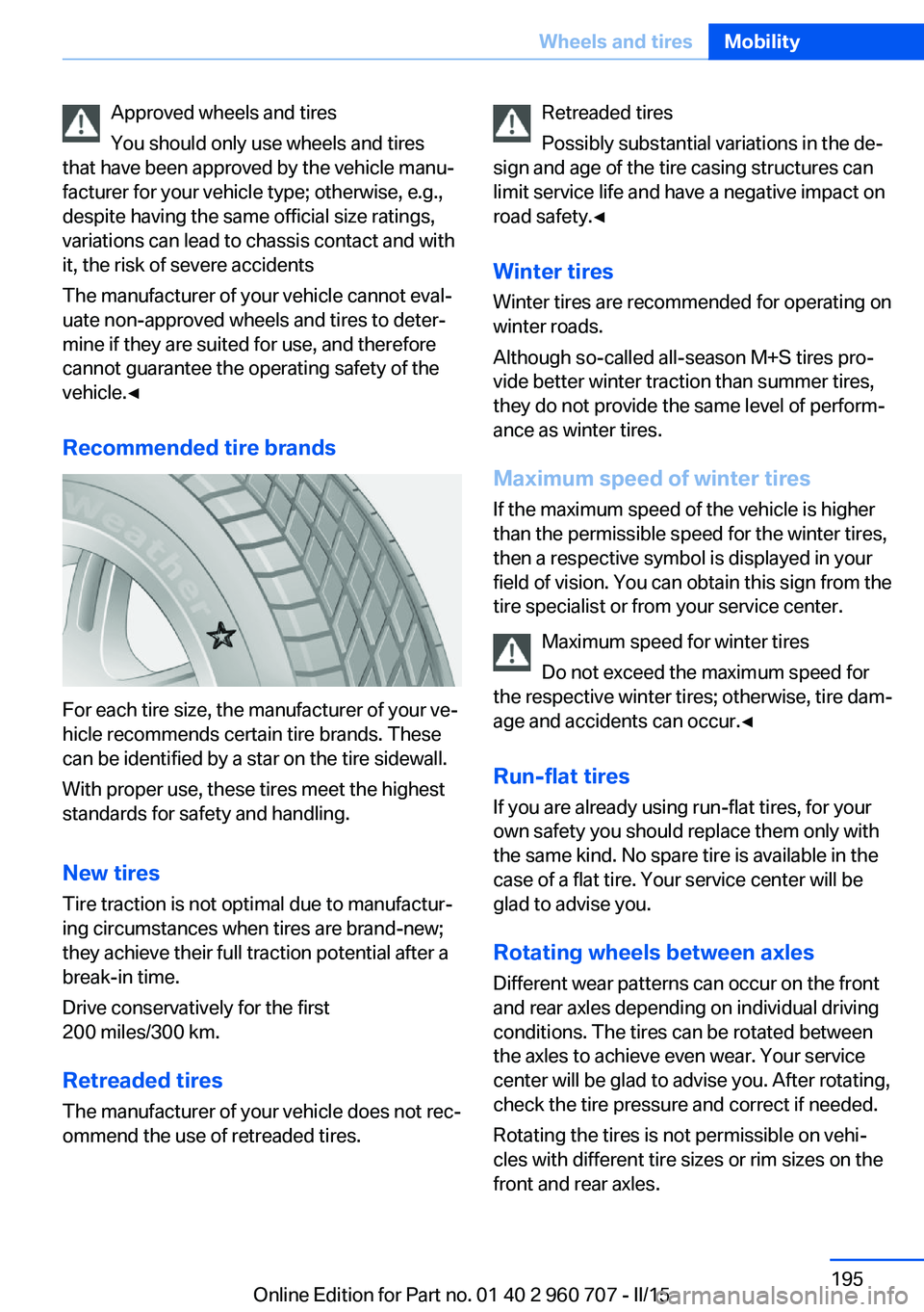
For each tire size, the manufacturer of your ve‐
hicle recommends certain tire brands. These
can be identified by a star on the tire sidewall.
With proper use, these tires meet the highest
standards for safety and handling.
New tires Tire traction is not optimal due to manufactur‐
ing circumstances when tires are brand-new;
they achieve their full traction potential after a
break-in time.
Drive conservatively for the first
200 miles/300 km.
Retreaded tires
The manufacturer of your vehicle does not rec‐
ommend the use of retreaded tires.
Retreaded tires
Possibly substantial variations in the de‐
sign and age of the tire casing structures can
limit service life and have a negative impact on
road safety.◀
Winter tires
Winter tires are recommended for operating on
winter roads.
Although so-called all-season M+S tires pro‐
vide better winter traction than summer tires, they do not provide the same level of perform‐
ance as winter tires.
Maximum speed of winter tires If the maximum speed of the vehicle is higher
than the permissible speed for the winter tires,
then a respective symbol is displayed in your
field of vision. You can obtain this sign from the
tire specialist or from your service center.
Maximum speed for winter tires
Do not exceed the maximum speed for
the respective winter tires; otherwise, tire dam‐
age and accidents can occur.◀
Run-flat tires If you are already using run-flat tires, for your
own safety you should replace them only with
the same kind. No spare tire is available in the
case of a flat tire. Your service center will be
glad to advise you.
Rotating wheels between axlesDifferent wear patterns can occur on the frontand rear axles depending on individual driving
conditions. The tires can be rotated between
the axles to achieve even wear. Your service
center will be glad to advise you. After rotating,
check the tire pressure and correct if needed.
Rotating the tires is not permissible on vehi‐
cles with different tire sizes or rim sizes on the
front and rear axles.Seite 195Wheels and tiresMobility195
Online Edition for Part no. 01 40 2 960 707 - II/15
Page 200 of 249
StorageStore wheels and tires in a cool, dry place with
as little exposure to light as possible.
Always protect tires against all contact with oil,
grease and fuels.
Do not exceed the maximum tire inflation pres‐
sure indicated on the side wall of the tire.
Run-flat tires Label
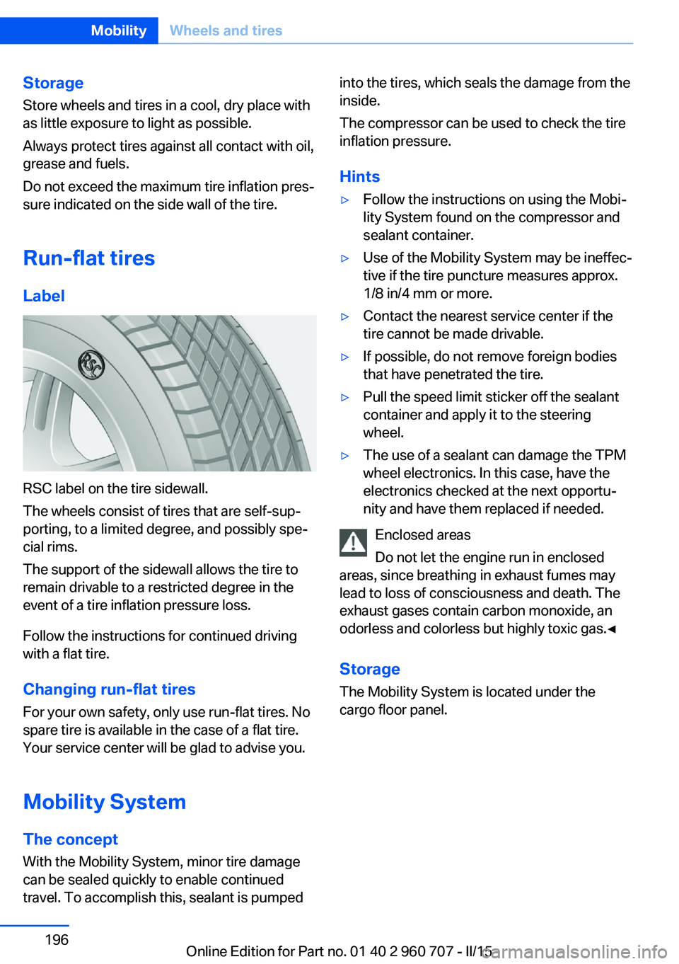
RSC label on the tire sidewall.
The wheels consist of tires that are self-sup‐
porting, to a limited degree, and possibly spe‐
cial rims.
The support of the sidewall allows the tire to
remain drivable to a restricted degree in the
event of a tire inflation pressure loss.
Follow the instructions for continued driving
with a flat tire.
Changing run-flat tires
For your own safety, only use run-flat tires. No
spare tire is available in the case of a flat tire.
Your service center will be glad to advise you.
Mobility System
The concept With the Mobility System, minor tire damagecan be sealed quickly to enable continued
travel. To accomplish this, sealant is pumped
into the tires, which seals the damage from the inside.
The compressor can be used to check the tire inflation pressure.
Hints▷Follow the instructions on using the Mobi‐
lity System found on the compressor and
sealant container.▷Use of the Mobility System may be ineffec‐
tive if the tire puncture measures approx.
1/8 in/4 mm or more.▷Contact the nearest service center if the
tire cannot be made drivable.▷If possible, do not remove foreign bodies
that have penetrated the tire.▷Pull the speed limit sticker off the sealant
container and apply it to the steering
wheel.▷The use of a sealant can damage the TPM
wheel electronics. In this case, have the
electronics checked at the next opportu‐
nity and have them replaced if needed.
Enclosed areas
Do not let the engine run in enclosed
areas, since breathing in exhaust fumes may
lead to loss of consciousness and death. The
exhaust gases contain carbon monoxide, an
odorless and colorless but highly toxic gas.◀
Storage The Mobility System is located under the
cargo floor panel.
Seite 196MobilityWheels and tires196
Online Edition for Part no. 01 40 2 960 707 - II/15
Page 201 of 249
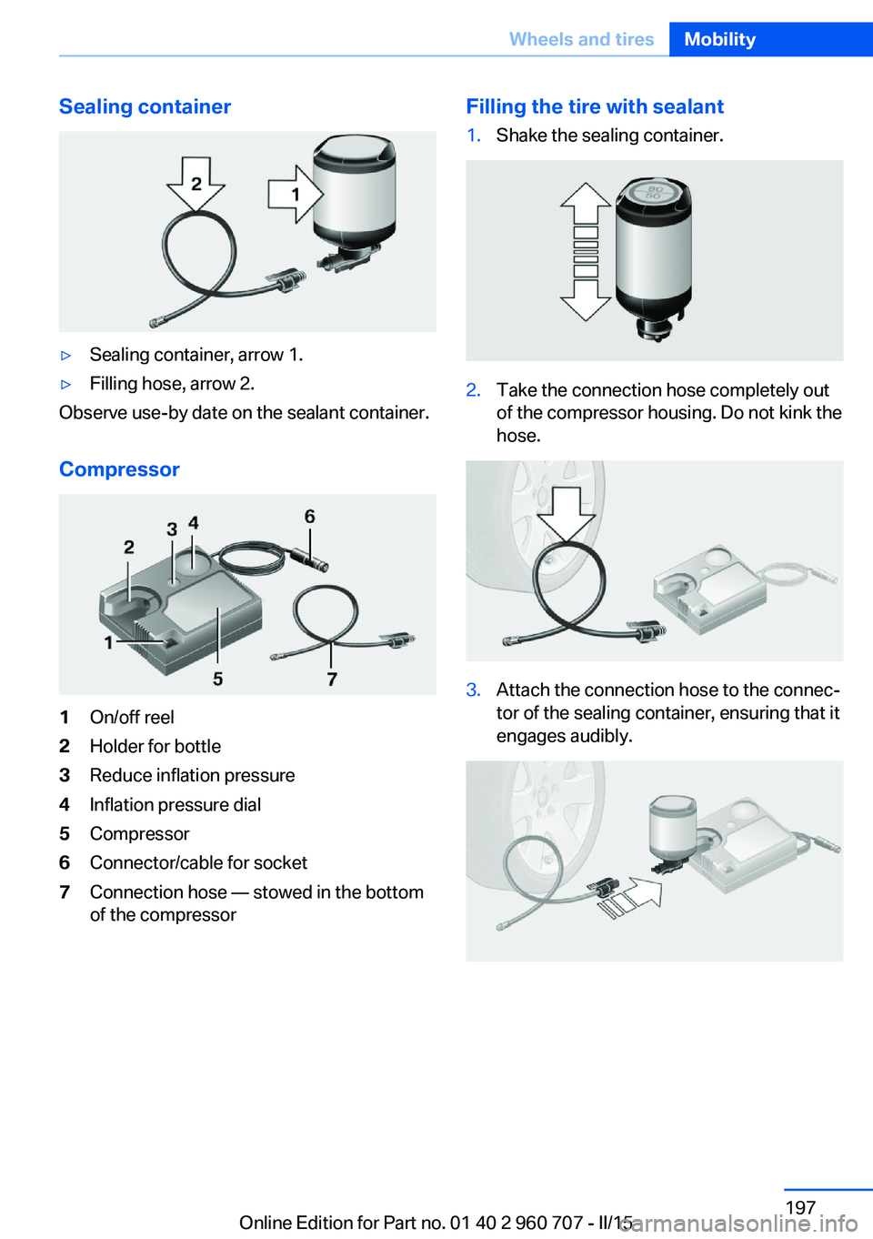
Sealing container▷Sealing container, arrow 1.▷Filling hose, arrow 2.
Observe use-by date on the sealant container.
Compressor
1On/off reel2Holder for bottle3Reduce inflation pressure4Inflation pressure dial5Compressor6Connector/cable for socket7Connection hose — stowed in the bottom
of the compressorFilling the tire with sealant1.Shake the sealing container.2.Take the connection hose completely out
of the compressor housing. Do not kink the
hose.3.Attach the connection hose to the connec‐
tor of the sealing container, ensuring that it
engages audibly.Seite 197Wheels and tiresMobility197
Online Edition for Part no. 01 40 2 960 707 - II/15
Page 202 of 249
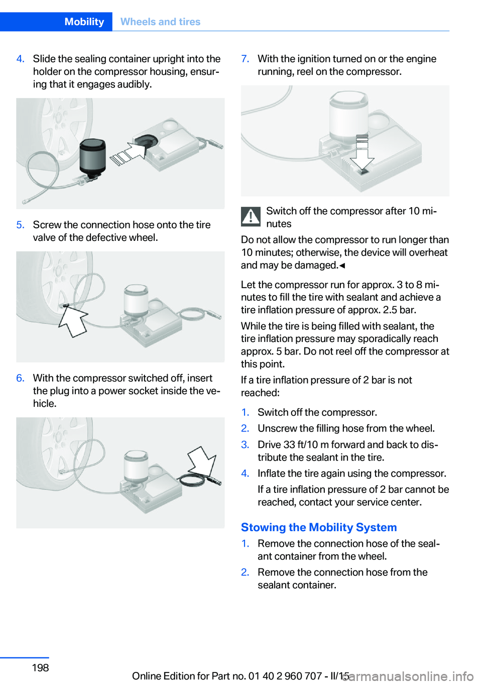
4.Slide the sealing container upright into the
holder on the compressor housing, ensur‐
ing that it engages audibly.5.Screw the connection hose onto the tire
valve of the defective wheel.6.With the compressor switched off, insert
the plug into a power socket inside the ve‐
hicle.7.With the ignition turned on or the engine
running, reel on the compressor.
Switch off the compressor after 10 mi‐
nutes
Do not allow the compressor to run longer than
10 minutes; otherwise, the device will overheat
and may be damaged.◀
Let the compressor run for approx. 3 to 8 mi‐
nutes to fill the tire with sealant and achieve a
tire inflation pressure of approx. 2.5 bar.
While the tire is being filled with sealant, the
tire inflation pressure may sporadically reach
approx. 5 bar. Do not reel off the compressor at
this point.
If a tire inflation pressure of 2 bar is not
reached:
1.Switch off the compressor.2.Unscrew the filling hose from the wheel.3.Drive 33 ft/10 m forward and back to dis‐
tribute the sealant in the tire.4.Inflate the tire again using the compressor.
If a tire inflation pressure of 2 bar cannot be
reached, contact your service center.
Stowing the Mobility System
1.Remove the connection hose of the seal‐
ant container from the wheel.2.Remove the connection hose from the
sealant container.Seite 198MobilityWheels and tires198
Online Edition for Part no. 01 40 2 960 707 - II/15
Page 203 of 249
3.Wrap the empty sealant container and con‐
nection hose in suitable material to avoid
dirtying the cargo area.4.Stow the Mobility System back in the vehi‐
cle.
Distributing the sealant
Immediately drive approx. 5 miles/10 km to en‐
sure that the sealant is evenly distributed in the
tire.
Do not exceed a speed of 50 mph/80 km/h.
If possible, do not drive at speeds less than
12 mph/20 km/h.
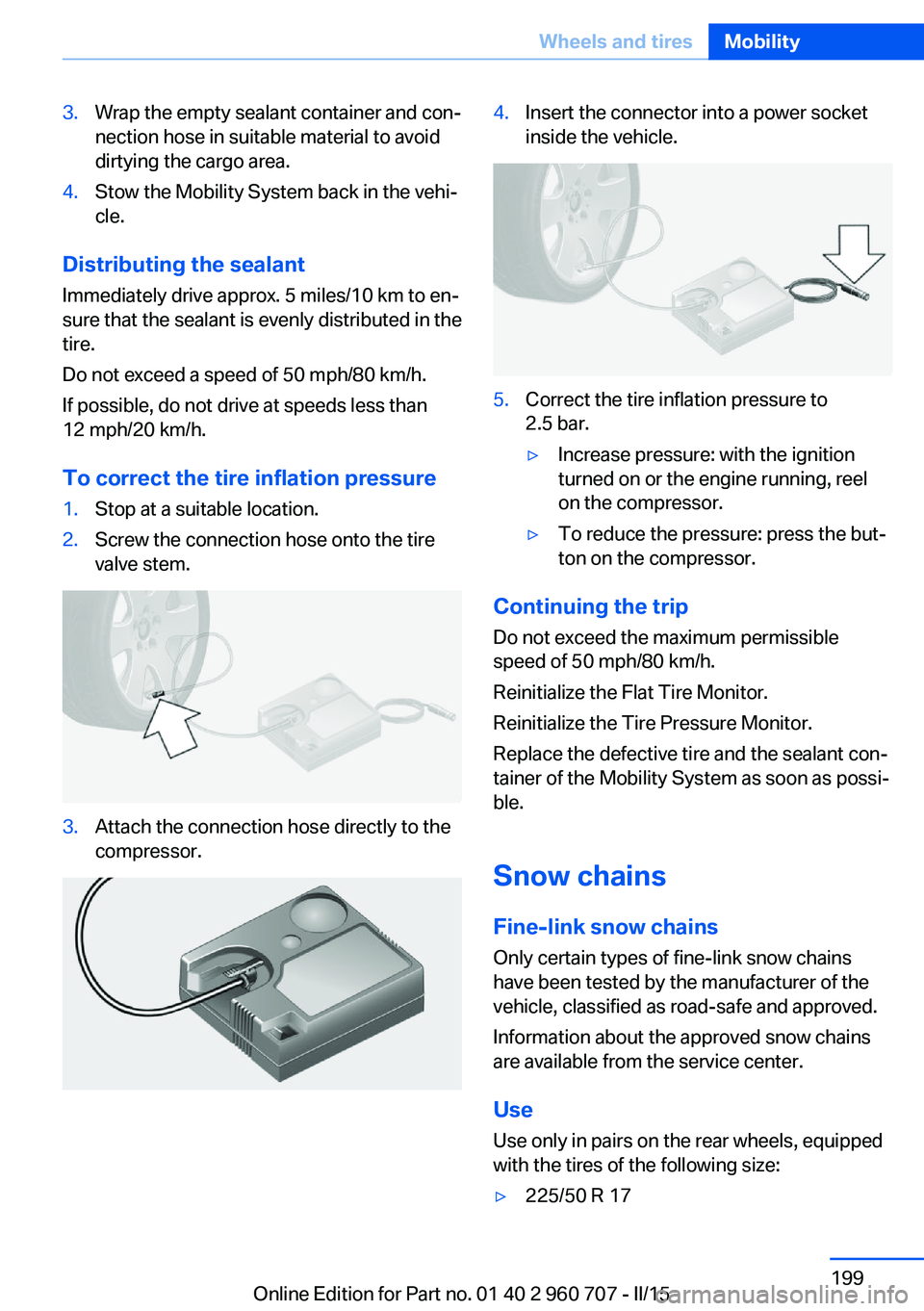
To correct the tire inflation pressure
1.Stop at a suitable location.2.Screw the connection hose onto the tire
valve stem.3.Attach the connection hose directly to the
compressor.4.Insert the connector into a power socket
inside the vehicle.5.Correct the tire inflation pressure to
2.5 bar.▷Increase pressure: with the ignition
turned on or the engine running, reel
on the compressor.▷To reduce the pressure: press the but‐
ton on the compressor.
Continuing the trip
Do not exceed the maximum permissible
speed of 50 mph/80 km/h.
Reinitialize the Flat Tire Monitor.
Reinitialize the Tire Pressure Monitor.
Replace the defective tire and the sealant con‐
tainer of the Mobility System as soon as possi‐
ble.
Snow chains Fine-link snow chains
Only certain types of fine-link snow chains
have been tested by the manufacturer of the
vehicle, classified as road-safe and approved.
Information about the approved snow chains
are available from the service center.
Use
Use only in pairs on the rear wheels, equipped
with the tires of the following size:
▷225/50 R 17Seite 199Wheels and tiresMobility199
Online Edition for Part no. 01 40 2 960 707 - II/15
Page 204 of 249
▷225/45 R 18
Follow the snow chain manufacturer's instruc‐
tions.
Make sure that the snow chains are always
sufficiently tight. Retighten as needed accord‐
ing to the chain manufacturer's instructions.
Do not initialize the Flat Tire Monitor after
mounting snow chains, as doing so may result
in incorrect readings.
Do not initialize the Tire Pressure Monitor after
mounting snow chains, as doing so may result
in incorrect readings.
When driving with snow chains, briefly activate
Dynamic Traction Control if needed.
Maximum speed with snow chains Do not exceed a speed of 30 mph/50 km/hwhen using snow chains.
Seite 200MobilityWheels and tires200
Online Edition for Part no. 01 40 2 960 707 - II/15
Page 215 of 249
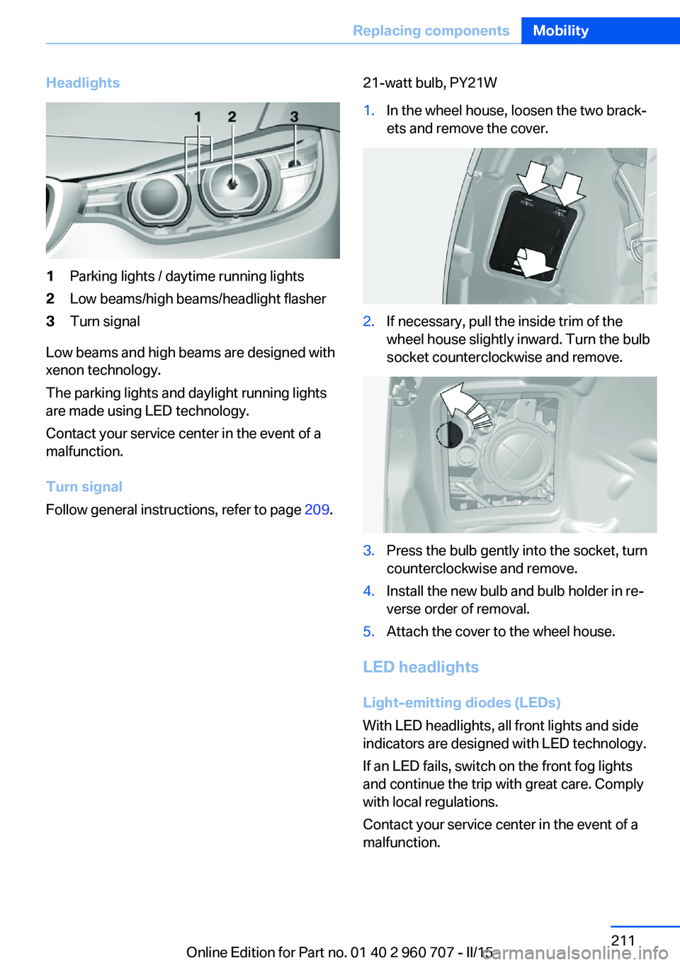
Headlights1Parking lights / daytime running lights2Low beams/high beams/headlight flasher3Turn signal
Low beams and high beams are designed with
xenon technology.
The parking lights and daylight running lights
are made using LED technology.
Contact your service center in the event of a
malfunction.
Turn signal
Follow general instructions, refer to page 209.
21-watt bulb, PY21W1.In the wheel house, loosen the two brack‐
ets and remove the cover.2.If necessary, pull the inside trim of the
wheel house slightly inward. Turn the bulb
socket counterclockwise and remove.3.Press the bulb gently into the socket, turn
counterclockwise and remove.4.Install the new bulb and bulb holder in re‐
verse order of removal.5.Attach the cover to the wheel house.
LED headlights
Light-emitting diodes (LEDs)
With LED headlights, all front lights and side
indicators are designed with LED technology.
If an LED fails, switch on the front fog lights
and continue the trip with great care. Comply
with local regulations.
Contact your service center in the event of a
malfunction.
Seite 211Replacing componentsMobility211
Online Edition for Part no. 01 40 2 960 707 - II/15
Page 216 of 249
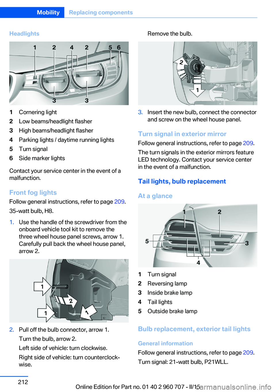
Headlights1Cornering light2Low beams/headlight flasher3High beams/headlight flasher4Parking lights / daytime running lights5Turn signal6Side marker lights
Contact your service center in the event of a
malfunction.
Front fog lights
Follow general instructions, refer to page 209.
35-watt bulb, H8.
1.Use the handle of the screwdriver from the
onboard vehicle tool kit to remove the
three wheel house panel screws, arrow 1.
Carefully pull back the wheel house panel,
arrow 2.2.Pull off the bulb connector, arrow 1.
Turn the bulb, arrow 2.
Left side of vehicle: turn clockwise.
Right side of vehicle: turn counterclock‐
wise.Remove the bulb.3.Insert the new bulb, connect the connector
and screw on the wheel house panel.
Turn signal in exterior mirror
Follow general instructions, refer to page 209.
The turn signals in the exterior mirrors feature
LED technology. Contact your service center
in the event of a malfunction.
Tail lights, bulb replacement
At a glance
1Turn signal2Reversing lamp3Inside brake lamp4Tail lights5Outside brake lamp
Bulb replacement, exterior tail lights General information
Follow general instructions, refer to page 209.
Turn signal: 21-watt bulb, P21WLL.
Seite 212MobilityReplacing components212
Online Edition for Part no. 01 40 2 960 707 - II/15
Page 219 of 249
These lights are made using LED technology.
Contact your service center in the event of a
malfunction.
Changing wheels
Hints When using run-flat tires or sealants, a tire
does not need to be changed immediately in
the event of pressure loss due to a flat tire.
Which is why no spare tire is available.
The tools for changing wheels are available as
accessories from your service center.
Jacking points for the vehicle jack
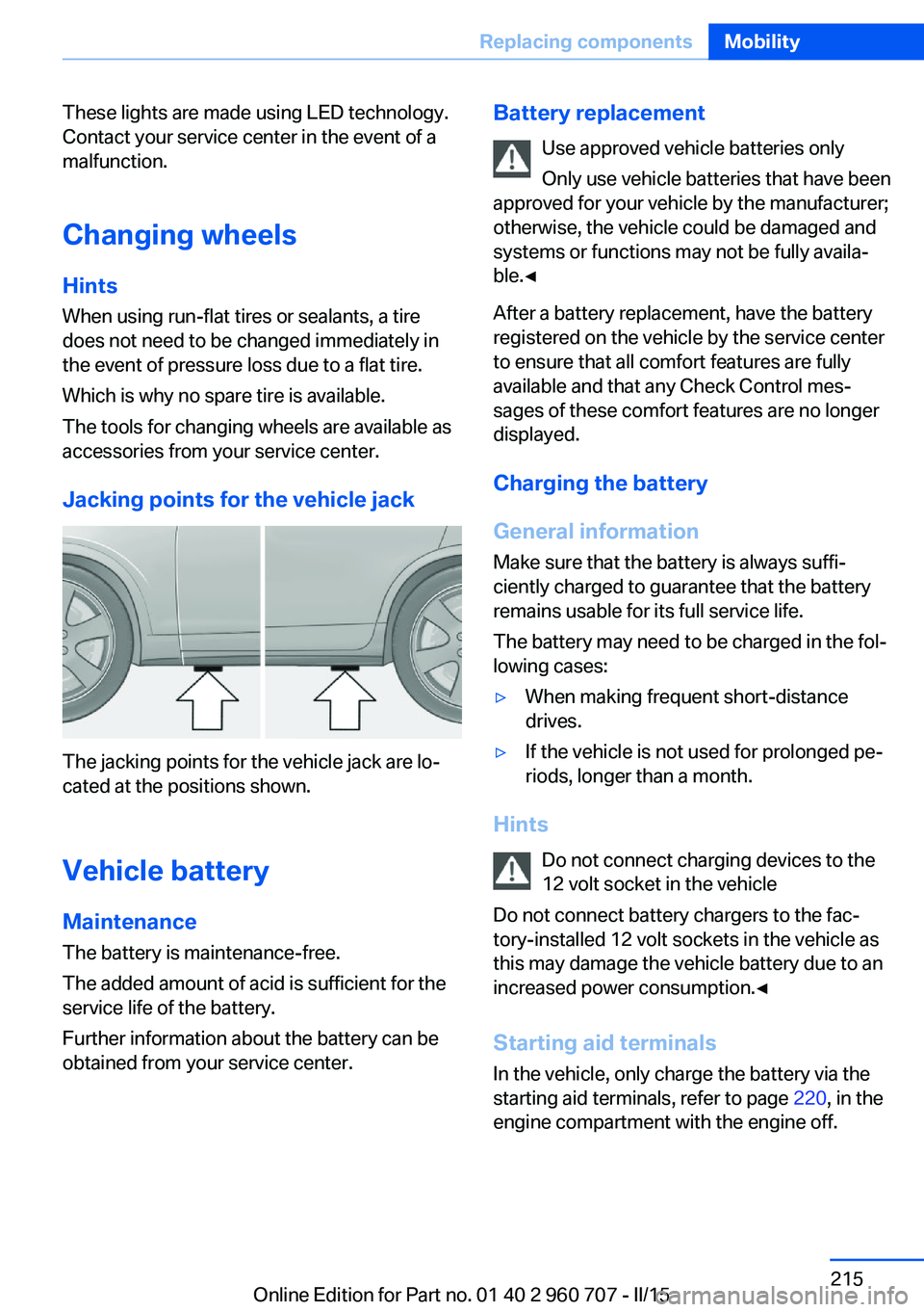
The jacking points for the vehicle jack are lo‐
cated at the positions shown.
Vehicle battery Maintenance
The battery is maintenance-free.
The added amount of acid is sufficient for the
service life of the battery.
Further information about the battery can be
obtained from your service center.
Battery replacement
Use approved vehicle batteries only
Only use vehicle batteries that have been
approved for your vehicle by the manufacturer;
otherwise, the vehicle could be damaged and
systems or functions may not be fully availa‐
ble.◀
After a battery replacement, have the battery registered on the vehicle by the service center
to ensure that all comfort features are fully
available and that any Check Control mes‐
sages of these comfort features are no longer
displayed.
Charging the battery
General information Make sure that the battery is always suffi‐
ciently charged to guarantee that the battery
remains usable for its full service life.
The battery may need to be charged in the fol‐
lowing cases:▷When making frequent short-distance
drives.▷If the vehicle is not used for prolonged pe‐
riods, longer than a month.
Hints
Do not connect charging devices to the
12 volt socket in the vehicle
Do not connect battery chargers to the fac‐
tory-installed 12 volt sockets in the vehicle as
this may damage the vehicle battery due to an
increased power consumption.◀
Starting aid terminals
In the vehicle, only charge the battery via the
starting aid terminals, refer to page 220, in the
engine compartment with the engine off.
Seite 215Replacing componentsMobility215
Online Edition for Part no. 01 40 2 960 707 - II/15
Page 225 of 249
Tow-starting and towingNote Tow-starting and towing
For tow-starting or towing, switch off the
Intelligent Safety systems; otherwise malfunc‐
tions of the individual braking systems might
lead to accidents.◀
Manual transmission Gearshift lever in neutral position.
Towing Follow the towing instructions
Follow all towing instructions; otherwise,
vehicle damage or accidents may occur.◀▷Make sure that the ignition is switched on;
otherwise, the low beams, tail lights, turn
signals, and wipers may be unavailable.▷Do not tow the vehicle with the rear axle
tilted, as the front wheels could turn.▷When the engine is stopped, there is no
power assist. Consequently, more force
needs to be applied when braking and
steering.▷Larger steering wheel movements are re‐
quired.▷The towing vehicle must not be lighter
than the vehicle being towed; otherwise,
it will not be possible to control the vehi‐
cle's response.Tow truck
With rear-wheel drive
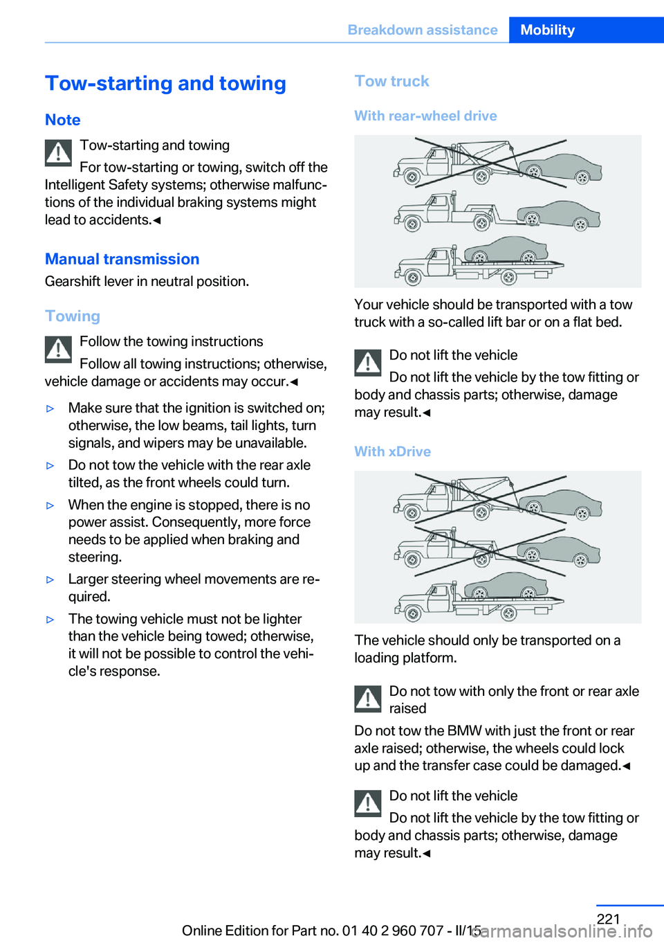
Your vehicle should be transported with a tow
truck with a so-called lift bar or on a flat bed.
Do not lift the vehicle
Do not lift the vehicle by the tow fitting or
body and chassis parts; otherwise, damage
may result.◀
With xDrive
The vehicle should only be transported on a
loading platform.
Do not tow with only the front or rear axle
raised
Do not tow the BMW with just the front or rear
axle raised; otherwise, the wheels could lock
up and the transfer case could be damaged.◀
Do not lift the vehicle
Do not lift the vehicle by the tow fitting or
body and chassis parts; otherwise, damage
may result.◀
Seite 221Breakdown assistanceMobility221
Online Edition for Part no. 01 40 2 960 707 - II/15