turn signal BMW 435I XDRIVE CONVERTIBLE 2016 User Guide
[x] Cancel search | Manufacturer: BMW, Model Year: 2016, Model line: 435I XDRIVE CONVERTIBLE, Model: BMW 435I XDRIVE CONVERTIBLE 2016Pages: 247, PDF Size: 5.22 MB
Page 120 of 247
‚Ė∑When using the turn signal.
System limits
The system may not be fully functional in the
following situations:
‚Ė∑In heavy fog, rain or snowfall.‚Ė∑In the event of missing, worn, poorly visi‚Äź
ble, merging, diverging, or multiple lane
markings such as in construction areas.‚Ė∑When lane markings are covered in snow,
ice, dirt or water.‚Ė∑In tight curves or on narrow lanes.‚Ė∑When the lane markings are covered by
objects.‚Ė∑When driving very close to the vehicle in
front of you.‚Ė∑When driving toward bright lights.‚Ė∑When the windshield in front of the interior
rearview mirror is fogged over, dirty or cov‚Äź
ered with stickers, etc.‚Ė∑During calibration of the camera immedi‚Äź
ately after vehicle shipment.
Active Blind Spot Detection
The concept
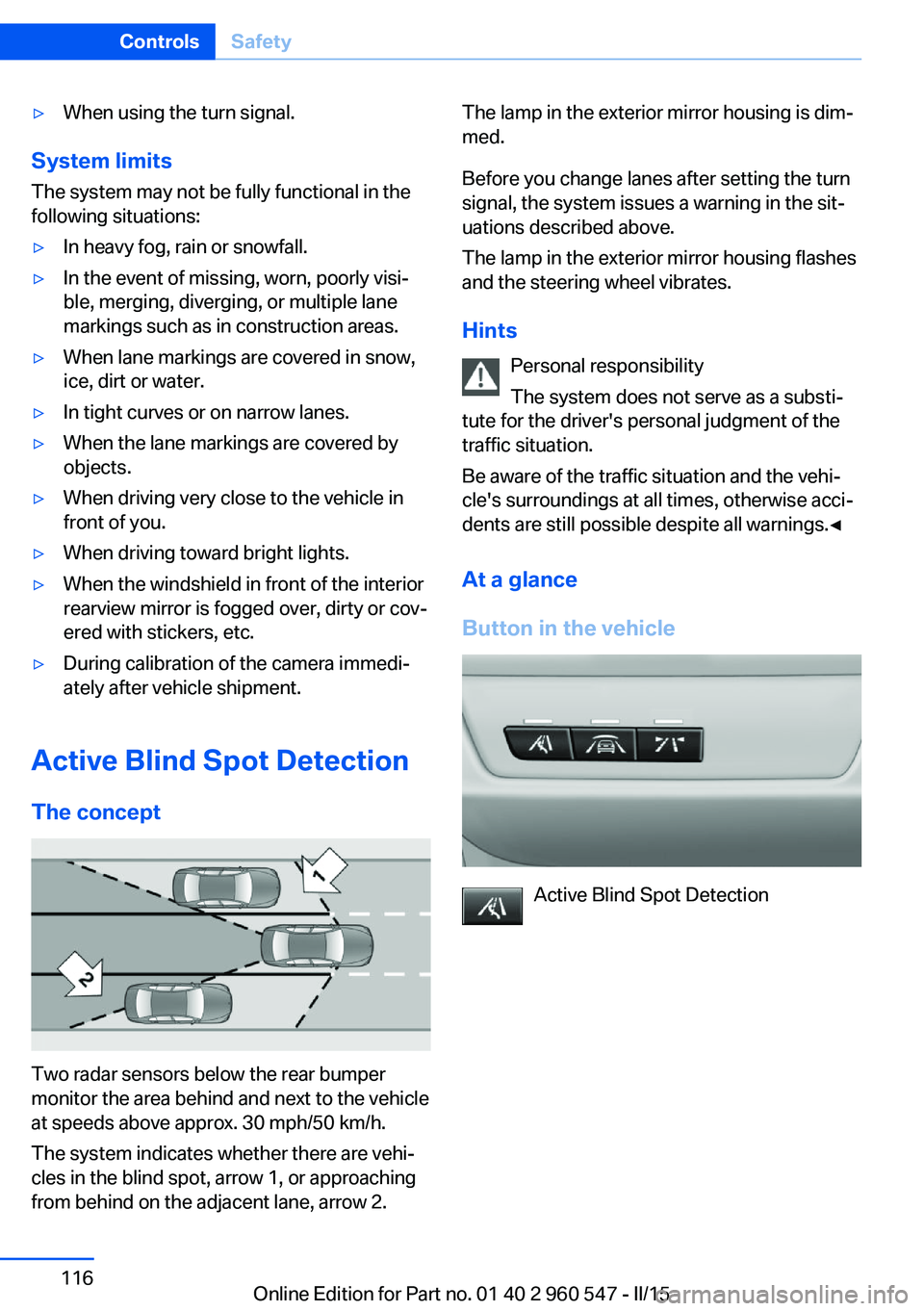
Two radar sensors below the rear bumper
monitor the area behind and next to the vehicle
at speeds above approx. 30 mph/50 km/h.
The system indicates whether there are vehi‚Äź
cles in the blind spot, arrow 1, or approaching
from behind on the adjacent lane, arrow 2.
The lamp in the exterior mirror housing is dim‚Äź
med.
Before you change lanes after setting the turn
signal, the system issues a warning in the sit‚Äź
uations described above.
The lamp in the exterior mirror housing flashes
and the steering wheel vibrates.
Hints Personal responsibility
The system does not serve as a substi‚Äź
tute for the driver's personal judgment of the
traffic situation.
Be aware of the traffic situation and the vehi‚Äź
cle's surroundings at all times, otherwise acci‚Äź
dents are still possible despite all warnings.‚óÄ
At a glance
Button in the vehicle
Active Blind Spot Detection
Seite 116ControlsSafety116
Online Edition for Part no. 01 40 2 960 547 - II/15
Page 121 of 247
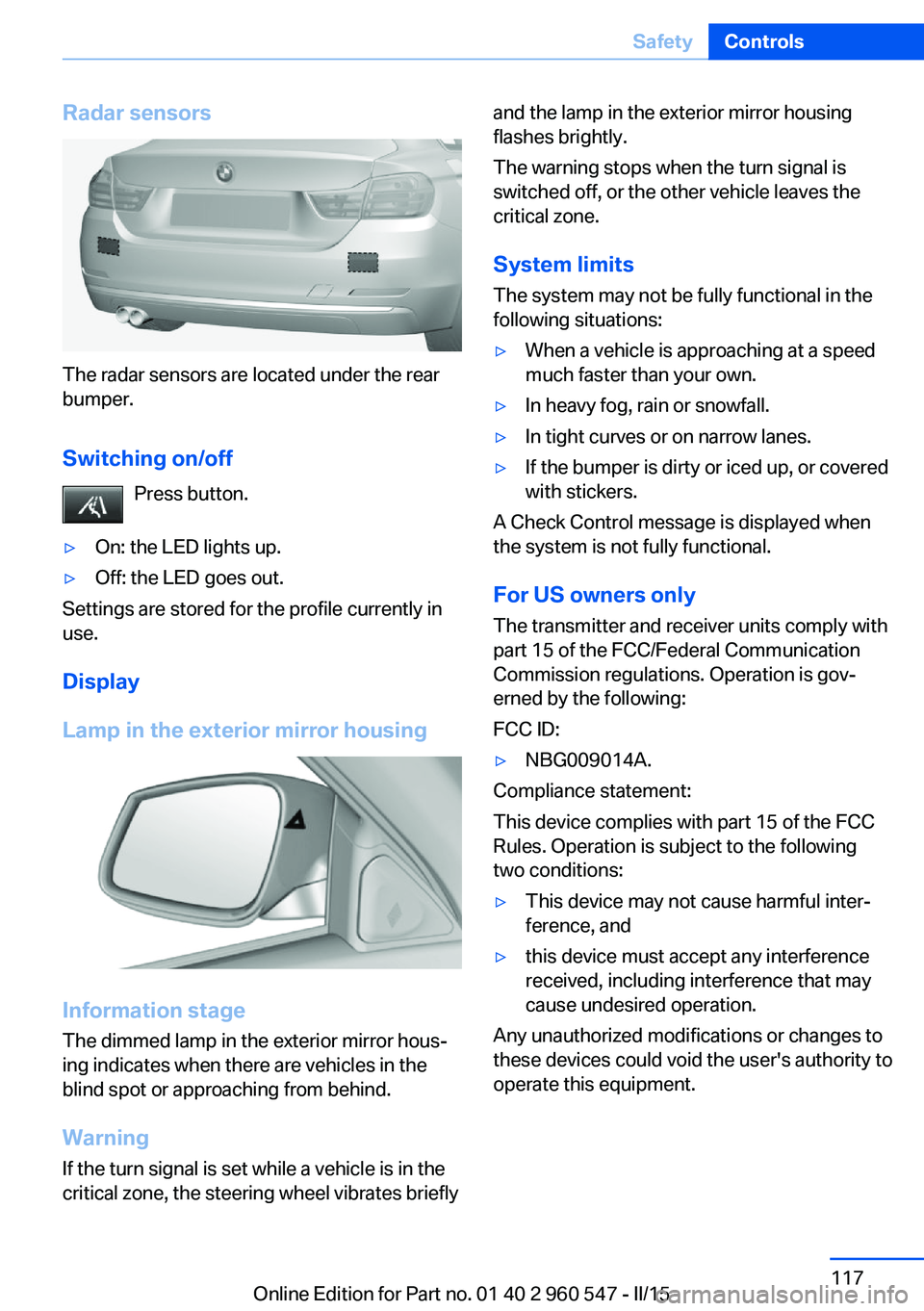
Radar sensors
The radar sensors are located under the rear
bumper.
Switching on/off Press button.
‚Ė∑On: the LED lights up.‚Ė∑Off: the LED goes out.
Settings are stored for the profile currently in
use.
Display
Lamp in the exterior mirror housing
Information stage
The dimmed lamp in the exterior mirror hous‚Äź
ing indicates when there are vehicles in the
blind spot or approaching from behind.
Warning If the turn signal is set while a vehicle is in the
critical zone, the steering wheel vibrates briefly
and the lamp in the exterior mirror housing
flashes brightly.
The warning stops when the turn signal is
switched off, or the other vehicle leaves the
critical zone.
System limits
The system may not be fully functional in the
following situations:‚Ė∑When a vehicle is approaching at a speed
much faster than your own.‚Ė∑In heavy fog, rain or snowfall.‚Ė∑In tight curves or on narrow lanes.‚Ė∑If the bumper is dirty or iced up, or covered
with stickers.
A Check Control message is displayed when
the system is not fully functional.
For US owners only The transmitter and receiver units comply with
part 15 of the FCC/Federal Communication
Commission regulations. Operation is gov‚Äź
erned by the following:
FCC ID:
‚Ė∑NBG009014A.
Compliance statement:
This device complies with part 15 of the FCC
Rules. Operation is subject to the following
two conditions:
‚Ė∑This device may not cause harmful inter‚Äź
ference, and‚Ė∑this device must accept any interference
received, including interference that may
cause undesired operation.
Any unauthorized modifications or changes to
these devices could void the user's authority to
operate this equipment.
Seite 117SafetyControls117
Online Edition for Part no. 01 40 2 960 547 - II/15
Page 136 of 247
When cruise control is maintained or stored,
DSC Dynamic Stability Control will be turned
on if needed.
Changing the speed
Press the rocker switch up or down repeatedly
until the desired speed is set.
If active, the displayed speed is stored and the
vehicle reaches the stored speed when the
road is clear.‚Ė∑Each time the rocker switch is pressed to
the point of resistance, the desired speed
increases or decreases by approx.
1 mph/1 km/h.‚Ė∑Each time the rocker switch is pressed
past the point of resistance, the desired
speed increases or decreases by a maxi‚Äź
mum of 5 mph/10 km/h.
The maximum speed that can be set de‚Äź
pends on the vehicle.‚Ė∑Pressing the rocker switch to the resist‚Äź
ance point and holding it accelerates or de‚Äź
celerates the vehicle without requiring
pressure on the accelerator pedal.
After the rocker switch is released, the ve‚Äź
hicle maintains its final speed. Pressing the
switch beyond the resistance point causes
the vehicle to accelerate more rapidly.
Resuming the desired speed
Press button.
The stored speed is reached and maintained. Displays in the instrument cluster
Indicator lamp Depending on how the vehicle is equip‚Äź
ped, the indicator lamp in the instru‚Äź
ment cluster indicates whether the sys‚Äź
tem is switched on.
Desired speed‚Ė∑The marking lights up green:
the system is active.‚Ė∑The marking lights up or‚Äź
ange: the system has been
interrupted.‚Ė∑The marking does not light up: the system
is switched off.
Brief status display
Selected desired speed.
If --- appears briefly on the display for Check
Control messages, it is possible that the sys‚Äź
tem requirements are currently not ready for
operations.
Displays in the Head-up Display Some system information can also be dis‚Äźplayed in the Head-up Display.
PDC Park Distance Control
The concept PDC is a support when parking. When you
slowly approach an object in the rear - or also
in the front of the vehicle if the feature is availa‚Äź
ble - then the object is reported through:
‚Ė∑Signal tones.‚Ė∑Visual display.
General information
Ultrasound sensors in the bumpers measure
the distances from objects.
The maneuvering range, depending on the ob‚Äź
stacle and environmental conditions, is approx.
6 ft/2 m.
An acoustic warning is first given:
‚Ė∑By the front sensors and the two rear cor‚Äź
ner sensors at approx. 24 in/60 cm.Seite 132ControlsDriving comfort132
Online Edition for Part no. 01 40 2 960 547 - II/15
Page 145 of 247
HintsPersonal responsibility
Even an active system does not relieve
the driver from personal responsibility while
driving.
Technically the system has its limits, it cannot
independently react to all traffic situations.
Monitor your driving, be on the alert, observe
the vehicle surroundings and other traffic and
react when needed - risk of accident.‚óÄ
Changes to the parking space
Changes to the parking space after it was
measured are not taken into account by the system.
Therefore, always be alert and ready to inter‚Äź
vene; otherwise, there is the risk of an acci‚Äź
dent.‚óÄ
Transporting cargo
Cargo that extends beyond the perimeter
of the vehicle is not taken into account by the
system during the parking procedure.
Therefore, always be alert and ready to inter‚Äź
vene; otherwise, there is the risk of an acci‚Äź
dent.‚óÄ
Curbs
The parking assistant may steer the vehi‚Äź
cle over or onto curb if need be.
Therefore, always be alert and ready to inter‚Äź
vene; otherwise, the wheels, tires, or the vehi‚Äź
cle may become damaged.‚óÄ
An engine that has been switched off by the
Auto Start Stop function is restarted automati‚Äź
cally when the parking assistant is activated.
Requirements
For measuring parking spaces‚Ė∑Maximum speed while driving forward ap‚Äź
prox. 22 mph/35 km/h.‚Ė∑Maximum distance to row of parked vehi‚Äź
cles: 5 ft/1.5 m.
Suitable parking space
‚Ė∑Gap between two objects with a minimum
length of approx. 5 ft/1.5 m.‚Ė∑Min. length of gap between two objects:
your vehicle's length plus approx.
4 ft/1.2 m.‚Ė∑Minimum depth: approx. 5 ft/1.5 m.
Regarding the parking procedure
‚Ė∑Doors and trunk lid closed.‚Ė∑Parking brake released.‚Ė∑When parking in parking spaces on the
driver's side, the corresponding turn signal
must be set where applicable.
Overview
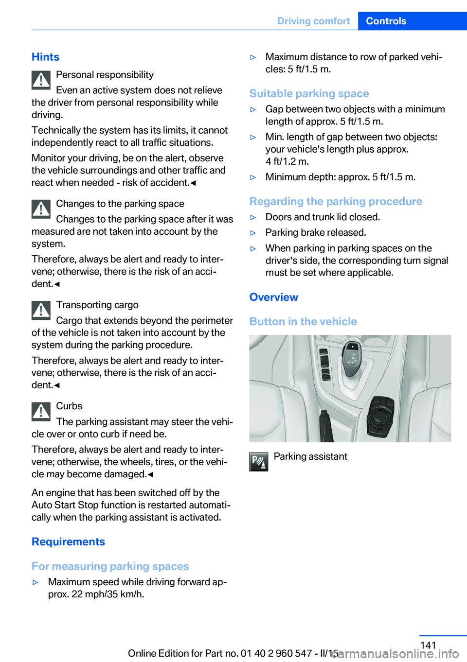
Button in the vehicle
Parking assistant
Seite 141Driving comfortControls141
Online Edition for Part no. 01 40 2 960 547 - II/15
Page 147 of 247
Parking using the parking assistantCheck the traffic situation as well
Louds noises outside and inside the ve‚Äź
hicle can drown out the parking assistant's and
PDC's signals.
Check the traffic situation around the vehicle
with your own eyes; otherwise, there is a dan‚Äź
ger of an accident.‚óÄ1.Switch on the parking assistant and acti‚Äź
vate it if needed.
The status of the parking space search is
indicated on the Control Display.2.Follow the instructions on the Control Dis‚Äź
play.
The best possible parking position will
come after gear change on the stationary
vehicle - wait for the automatic steering
wheel move.
The end of the parking procedure is indi‚Äź
cated on the Control Display.3.Adjust the parking position yourself if
needed.
Interrupting manually
The parking assistant can be interrupted at any
time:
‚Ė∑ "Parking Assistant" Select the symbol
on the Control Display.‚Ė∑Press button.
Interrupting automatically
The system is interrupted automatically in the
following situations:
‚Ė∑If the driver grasps the steering wheel or if
he takes over steering.‚Ė∑If a gear is selected that does not match
the instruction on the Control Display.‚Ė∑If the vehicle speed exceeds approx.
6 mph/10 km/h.‚Ė∑Possible on snow-covered or slippery road
surfaces.‚Ė∑When there are obstacles that are hard to
overcome, such as curbs.‚Ė∑When there are obstacles that suddenly
arise.‚Ė∑If the Park Distance Control PDC displays
clearances that are too small.‚Ė∑If a maximum number of parking attempts
or the time taken for parking is exceeded.‚Ė∑If a turn signal has been actuated contrary
to the desired side for parking.‚Ė∑When switching to another function on the
Control Display.
A Check Control message is displayed.
Resume An interrupted parking procedure can be con‚Äź
tinued if needed.
Follow the instructions on the Control Display
to do this.
System limits
No parking assistance
The parking assistant does not offer assis‚Äź
tance in the following situations:
‚Ė∑In tight curves.
Functional limitations
The system may not be fully functional in the
following situations:
‚Ė∑On bumpy road surfaces such as gravel
roads.‚Ė∑On slippery ground.‚Ė∑On steep uphill or downhill grades.‚Ė∑With accumulations of leaves/snow in the
parking space.
Limits of ultrasonic measurement
Ultrasonic measuring might not function under
the following circumstances:
Seite 143Driving comfortControls143
Online Edition for Part no. 01 40 2 960 547 - II/15
Page 213 of 247
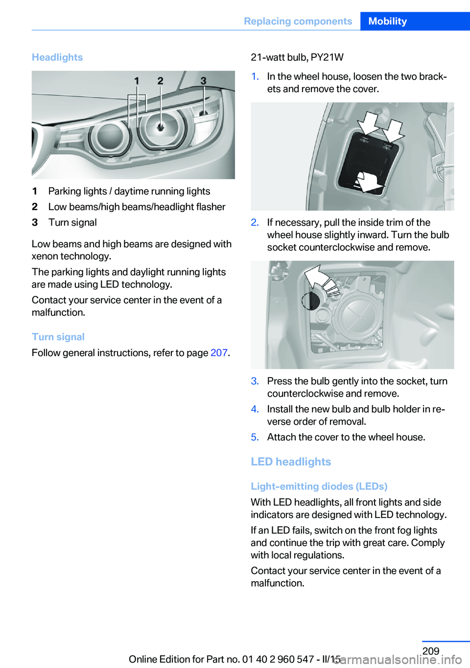
Headlights1Parking lights / daytime running lights2Low beams/high beams/headlight flasher3Turn signal
Low beams and high beams are designed with
xenon technology.
The parking lights and daylight running lights
are made using LED technology.
Contact your service center in the event of a
malfunction.
Turn signal
Follow general instructions, refer to page 207.
21-watt bulb, PY21W1.In the wheel house, loosen the two brack‚Äź
ets and remove the cover.2.If necessary, pull the inside trim of the
wheel house slightly inward. Turn the bulb
socket counterclockwise and remove.3.Press the bulb gently into the socket, turn
counterclockwise and remove.4.Install the new bulb and bulb holder in re‚Äź
verse order of removal.5.Attach the cover to the wheel house.
LED headlights
Light-emitting diodes (LEDs)
With LED headlights, all front lights and side
indicators are designed with LED technology.
If an LED fails, switch on the front fog lights
and continue the trip with great care. Comply
with local regulations.
Contact your service center in the event of a
malfunction.
Seite 209Replacing componentsMobility209
Online Edition for Part no. 01 40 2 960 547 - II/15
Page 214 of 247
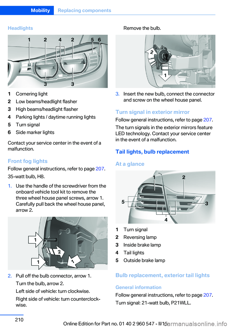
Headlights1Cornering light2Low beams/headlight flasher3High beams/headlight flasher4Parking lights / daytime running lights5Turn signal6Side marker lights
Contact your service center in the event of a
malfunction.
Front fog lights
Follow general instructions, refer to page 207.
35-watt bulb, H8.
1.Use the handle of the screwdriver from the
onboard vehicle tool kit to remove the
three wheel house panel screws, arrow 1.
Carefully pull back the wheel house panel,
arrow 2.2.Pull off the bulb connector, arrow 1.
Turn the bulb, arrow 2.
Left side of vehicle: turn clockwise.
Right side of vehicle: turn counterclock‚Äź
wise.Remove the bulb.3.Insert the new bulb, connect the connector
and screw on the wheel house panel.
Turn signal in exterior mirror
Follow general instructions, refer to page 207.
The turn signals in the exterior mirrors feature
LED technology. Contact your service center
in the event of a malfunction.
Tail lights, bulb replacement
At a glance
1Turn signal2Reversing lamp3Inside brake lamp4Tail lights5Outside brake lamp
Bulb replacement, exterior tail lights General information
Follow general instructions, refer to page 207.
Turn signal: 21-watt bulb, P21WLL.
Seite 210MobilityReplacing components210
Online Edition for Part no. 01 40 2 960 547 - II/15
Page 226 of 247
2.Engage selector lever position N.3.Switch the engine off.
In this way, the ignition remains switched
on, and a Check-Control message is dis‚Äź
played.
Do not turn off the ignition in the car
wash
Do not turn off the ignition in the car wash;
otherwise, selector lever position P is en‚Äź
gaged and damages can result.‚óÄ
The vehicle cannot be locked from the outside
when in selector lever position N. A signal
sounds when an attempt is made to lock the
vehicle.
To start the engine with Steptronic transmis‚Äź
sion:
1.Depress the brake pedal.2.Press the Start/Stop button.
Pressing the Start/Stop button without step‚Äź
ping on the brake turns the ignition off.
Selector lever positionSelector lever position P is engaged automati‚Äź
cally:
‚Ė∑When the ignition is switched off.‚Ė∑After approx. 15 minutes.
Headlights
‚Ė∑Do not rub dry and do not use abrasive or
acidic cleansers.‚Ė∑Soak areas that have been dirtied e. g.,
from insects, with shampoo and wash off
with water.‚Ė∑Thaw ice with de-icing spray; do not use an
ice scraper.
Lowerable hardtop
When the wet hardtop is opened, water drop‚Äź
lets can run into the trunk. Remove any objects
in the trunk beforehand to prevent water spot‚Äź
ting or soiling.
After washing the vehicle
After washing the vehicle, apply the brakes
briefly to dry them; otherwise, braking action
can be reduced and corrosion of the brake
discs can occur.
Completely remove all residues on the win‚Äź
dows, to minimize loss of visibility due to
smearing and to reduce wiper noises and
wiper blade wear.
Vehicle care
Car care products BMW recommends using care and cleaning
products from BMW, since these have been
tested and approved.
Car care and cleaning products
Follow the instructions on the container.
When cleaning the interior, open the doors or
windows.
Only use products intended for cleaning vehi‚Äź
cles.
Cleansers can contain substances that are
dangerous and harmful to your health.‚óÄ
Vehicle paint
Regular care contributes to driving safety and
value retention. Environmental influences in
areas with elevated air pollution or natural con‚Äź
taminants, such as tree resin or pollen can af‚Äź
fect the vehicle's paintwork. Tailor the fre‚Äź
quency and extent of your car care to these
influences.
Aggressive substances such as spilled fuel, oil,
grease or bird droppings, must be removed im‚Äź
mediately to prevent the finish from being al‚Äź
tered or discolored.
Leather care
Remove dust from the leather often, using a
cloth or vacuum cleaner.Seite 222MobilityCare222
Online Edition for Part no. 01 40 2 960 547 - II/15
Page 237 of 247
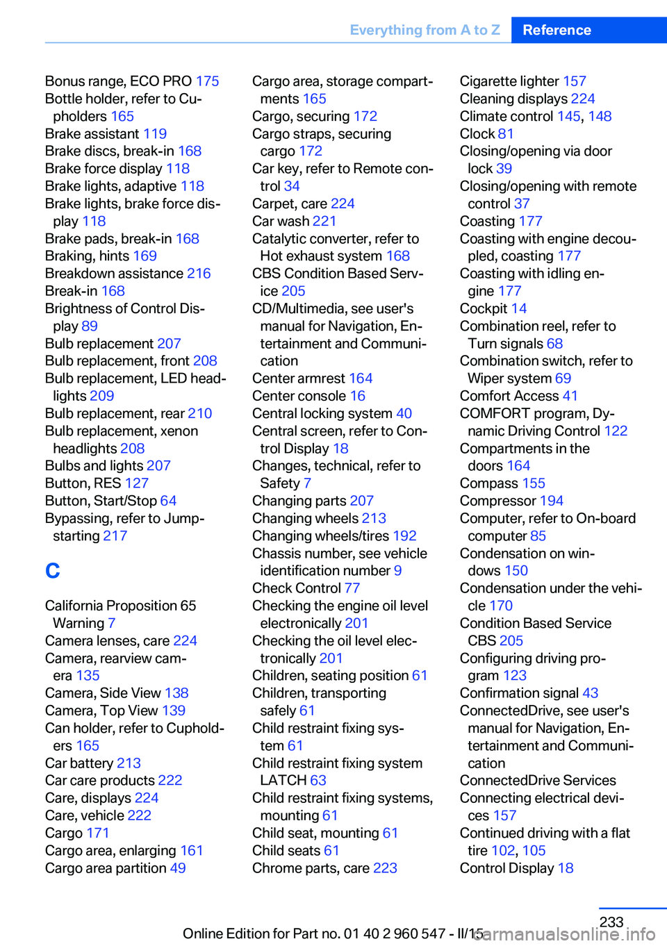
Bonus range, ECO PRO 175
Bottle holder, refer to Cu‚Äź pholders 165
Brake assistant 119
Brake discs, break-in 168
Brake force display 118
Brake lights, adaptive 118
Brake lights, brake force dis‚Äź play 118
Brake pads, break-in 168
Braking, hints 169
Breakdown assistance 216
Break-in 168
Brightness of Control Dis‚Äź play 89
Bulb replacement 207
Bulb replacement, front 208
Bulb replacement, LED head‚Äź lights 209
Bulb replacement, rear 210
Bulb replacement, xenon headlights 208
Bulbs and lights 207
Button, RES 127
Button, Start/Stop 64
Bypassing, refer to Jump- starting 217
C
California Proposition 65 Warning 7
Camera lenses, care 224
Camera, rearview cam‚Äź era 135
Camera, Side View 138
Camera, Top View 139
Can holder, refer to Cuphold‚Äź ers 165
Car battery 213
Car care products 222
Care, displays 224
Care, vehicle 222
Cargo 171
Cargo area, enlarging 161
Cargo area partition 49 Cargo area, storage compart‚Äź
ments 165
Cargo, securing 172
Cargo straps, securing cargo 172
Car key, refer to Remote con‚Äź trol 34
Carpet, care 224
Car wash 221
Catalytic converter, refer to Hot exhaust system 168
CBS Condition Based Serv‚Äź ice 205
CD/Multimedia, see user's manual for Navigation, En‚Äź
tertainment and Communi‚Äź
cation
Center armrest 164
Center console 16
Central locking system 40
Central screen, refer to Con‚Äź trol Display 18
Changes, technical, refer to Safety 7
Changing parts 207
Changing wheels 213
Changing wheels/tires 192
Chassis number, see vehicle identification number 9
Check Control 77
Checking the engine oil level electronically 201
Checking the oil level elec‚Äź tronically 201
Children, seating position 61
Children, transporting safely 61
Child restraint fixing sys‚Äź tem 61
Child restraint fixing system LATCH 63
Child restraint fixing systems, mounting 61
Child seat, mounting 61
Child seats 61
Chrome parts, care 223 Cigarette lighter 157
Cleaning displays 224
Climate control 145, 148
Clock 81
Closing/opening via door lock 39
Closing/opening with remote control 37
Coasting 177
Coasting with engine decou‚Äź pled, coasting 177
Coasting with idling en‚Äź gine 177
Cockpit 14
Combination reel, refer to Turn signals 68
Combination switch, refer to Wiper system 69
Comfort Access 41
COMFORT program, Dy‚Äź namic Driving Control 122
Compartments in the doors 164
Compass 155
Compressor 194
Computer, refer to On-board computer 85
Condensation on win‚Äź dows 150
Condensation under the vehi‚Äź cle 170
Condition Based Service CBS 205
Configuring driving pro‚Äź gram 123
Confirmation signal 43
ConnectedDrive, see user's manual for Navigation, En‚Äź
tertainment and Communi‚Äź
cation
ConnectedDrive Services
Connecting electrical devi‚Äź ces 157
Continued driving with a flat tire 102 , 105
Control Display 18 Seite 233Everything from A to ZReference233
Online Edition for Part no. 01 40 2 960 547 - II/15
Page 238 of 247
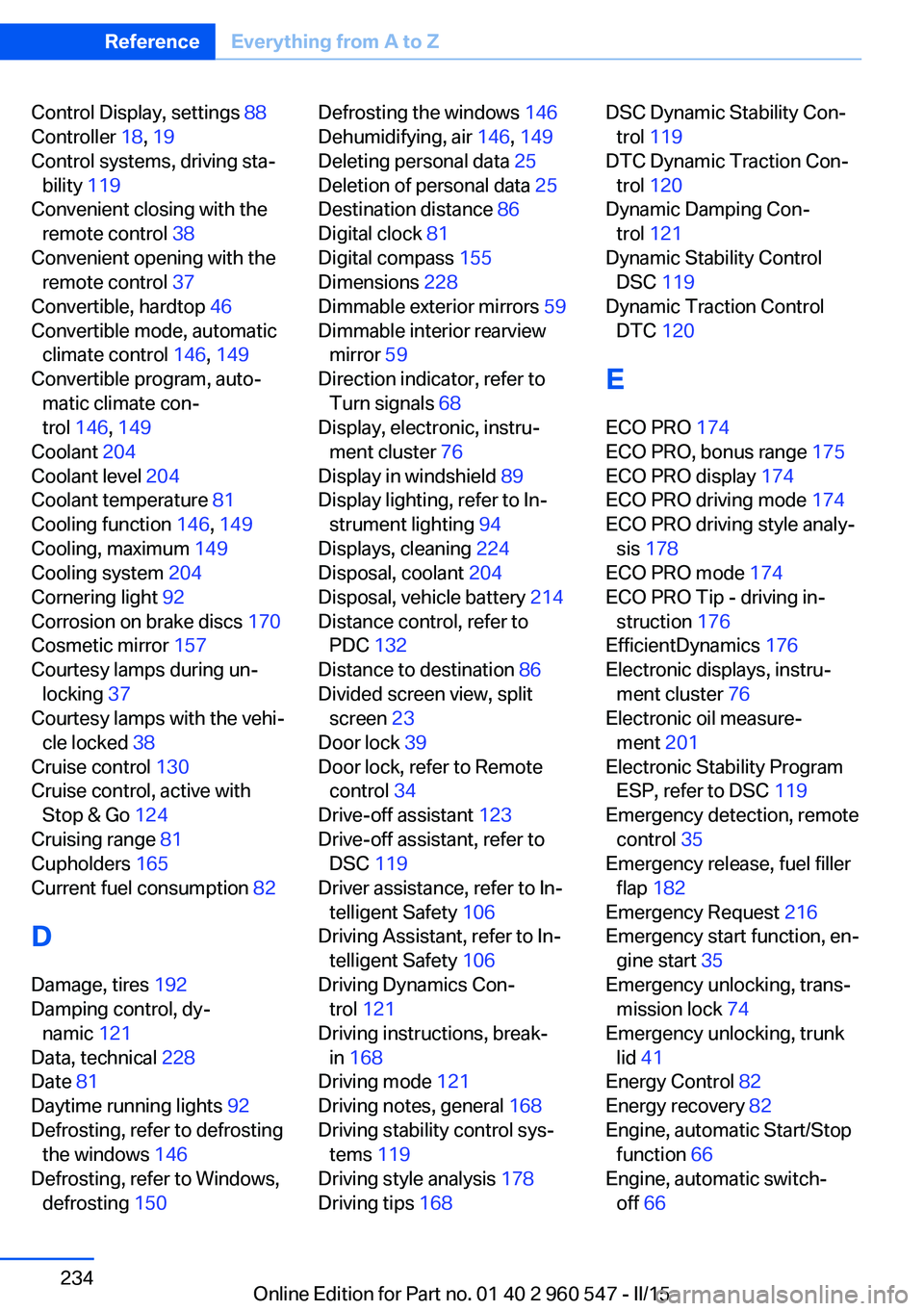
Control Display, settings 88
Controller 18, 19
Control systems, driving sta‚Äź bility 119
Convenient closing with the remote control 38
Convenient opening with the remote control 37
Convertible, hardtop 46
Convertible mode, automatic climate control 146, 149
Convertible program, auto‚Äź matic climate con‚Äź
trol 146 , 149
Coolant 204
Coolant level 204
Coolant temperature 81
Cooling function 146, 149
Cooling, maximum 149
Cooling system 204
Cornering light 92
Corrosion on brake discs 170
Cosmetic mirror 157
Courtesy lamps during un‚Äź locking 37
Courtesy lamps with the vehi‚Äź cle locked 38
Cruise control 130
Cruise control, active with Stop & Go 124
Cruising range 81
Cupholders 165
Current fuel consumption 82
D
Damage, tires 192
Damping control, dy‚Äź namic 121
Data, technical 228
Date 81
Daytime running lights 92
Defrosting, refer to defrosting the windows 146
Defrosting, refer to Windows, defrosting 150 Defrosting the windows 146
Dehumidifying, air 146, 149
Deleting personal data 25
Deletion of personal data 25
Destination distance 86
Digital clock 81
Digital compass 155
Dimensions 228
Dimmable exterior mirrors 59
Dimmable interior rearview mirror 59
Direction indicator, refer to Turn signals 68
Display, electronic, instru‚Äź ment cluster 76
Display in windshield 89
Display lighting, refer to In‚Äź strument lighting 94
Displays, cleaning 224
Disposal, coolant 204
Disposal, vehicle battery 214
Distance control, refer to PDC 132
Distance to destination 86
Divided screen view, split screen 23
Door lock 39
Door lock, refer to Remote control 34
Drive-off assistant 123
Drive-off assistant, refer to DSC 119
Driver assistance, refer to In‚Äź telligent Safety 106
Driving Assistant, refer to In‚Äź telligent Safety 106
Driving Dynamics Con‚Äź trol 121
Driving instructions, break- in 168
Driving mode 121
Driving notes, general 168
Driving stability control sys‚Äź tems 119
Driving style analysis 178
Driving tips 168 DSC Dynamic Stability Con‚Äź
trol 119
DTC Dynamic Traction Con‚Äź trol 120
Dynamic Damping Con‚Äź trol 121
Dynamic Stability Control DSC 119
Dynamic Traction Control DTC 120
E
ECO PRO 174
ECO PRO, bonus range 175
ECO PRO display 174
ECO PRO driving mode 174
ECO PRO driving style analy‚Äź sis 178
ECO PRO mode 174
ECO PRO Tip - driving in‚Äź struction 176
EfficientDynamics 176
Electronic displays, instru‚Äź ment cluster 76
Electronic oil measure‚Äź ment 201
Electronic Stability Program ESP, refer to DSC 119
Emergency detection, remote control 35
Emergency release, fuel filler flap 182
Emergency Request 216
Emergency start function, en‚Äź gine start 35
Emergency unlocking, trans‚Äź mission lock 74
Emergency unlocking, trunk lid 41
Energy Control 82
Energy recovery 82
Engine, automatic Start/Stop function 66
Engine, automatic switch- off 66 Seite 234ReferenceEverything from A to Z234
Online Edition for Part no. 01 40 2 960 547 - II/15