alignment BMW 5 SERIES 1991 E34 Owner's Manual
[x] Cancel search | Manufacturer: BMW, Model Year: 1991, Model line: 5 SERIES, Model: BMW 5 SERIES 1991 E34Pages: 228, PDF Size: 7.04 MB
Page 207 of 228
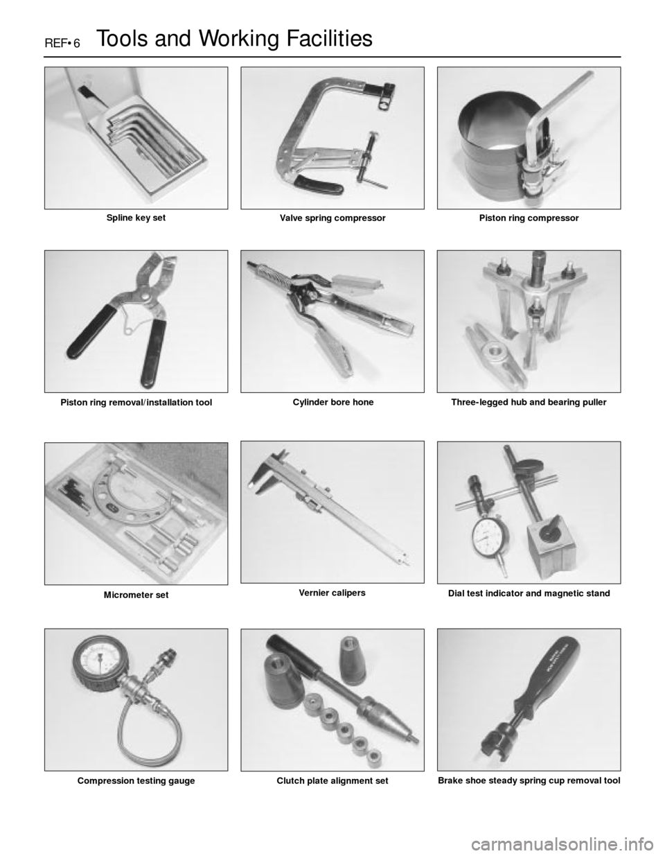
REF•6Tools and Working Facilities
Compression testing gauge Clutch plate alignment setBrake shoe steady spring cup removal tool
Micrometer setVernier calipers
Dial test indicator and magnetic stand
Piston ring removal/installation toolCylinder bore hone Three-legged hub and bearing puller
Valve spring compressorPiston ring compressorSpline key set
Page 208 of 228
REF•7
REF
Tools and Working Facilities
MImpact screwdriver
MMicrometer and/or vernier calipers (see
illustrations)
MDial gauge (see illustration)
MUniversal electrical multi-meter
MCylinder compression gauge
(see illustration)
MClutch plate alignment set (see illustration)
MBrake shoe steady spring cup removal tool
(see illustration)
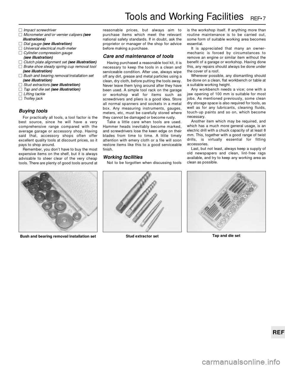
MBush and bearing removal/installation set
(see illustration)
MStud extractors (see illustration)
MTap and die set (see illustration)
MLifting tackle
MTrolley jack
Buying tools
For practically all tools, a tool factor is the
best source, since he will have a very
comprehensive range compared with the
average garage or accessory shop. Having
said that, accessory shops often offer
excellent quality tools at discount prices, so it
pays to shop around.
Remember, you don’t have to buy the most
expensive items on the shelf, but it is always
advisable to steer clear of the very cheap
tools. There are plenty of good tools around atreasonable prices, but always aim to
purchase items which meet the relevant
national safety standards. If in doubt, ask the
proprietor or manager of the shop for advice
before making a purchase.
Care and maintenance of tools
Having purchased a reasonable tool kit, it is
necessary to keep the tools in a clean and
serviceable condition. After use, always wipe
off any dirt, grease and metal particles using a
clean, dry cloth, before putting the tools away.
Never leave them lying around after they have
been used. A simple tool rack on the garage
or workshop wall for items such as
screwdrivers and pliers is a good idea. Store
all normal spanners and sockets in a metal
box. Any measuring instruments, gauges,
meters, etc, must be carefully stored where
they cannot be damaged or become rusty.
Take a little care when tools are used.
Hammer heads inevitably become marked,
and screwdrivers lose the keen edge on their
blades from time to time. A little timely
attention with emery cloth or a file will soon
restore items like this to a good serviceable
finish.
Working facilities
Not to be forgotten when discussing toolsis the workshop itself. If anything more than
routine maintenance is to be carried out,
some form of suitable working area becomes
essential.
It is appreciated that many an owner-
mechanic is forced by circumstances to
remove an engine or similar item without the
benefit of a garage or workshop. Having done
this, any repairs should always be done under
the cover of a roof.
Wherever possible, any dismantling should
be done on a clean, flat workbench or table at
a suitable working height.
Any workbench needs a vice; one with a
jaw opening of 100 mm is suitable for most
jobs. As mentioned previously, some clean
dry storage space is also required for tools, as
well as for any lubricants, cleaning fluids,
touch-up paints and so on, which become
necessary.
Another item which may be required, and
which has a much more general usage, is an
electric drill with a chuck capacity of at least 8
mm. This, together with a good range of twist
drills, is virtually essential for fitting
accessories.
Last, but not least, always keep a supply of
old newspapers and clean, lint-free rags
available, and try to keep any working area as
clean as possible.
Bush and bearing removal/installation setStud extractor setTap and die set
Page 215 of 228
REF•14Fault Finding
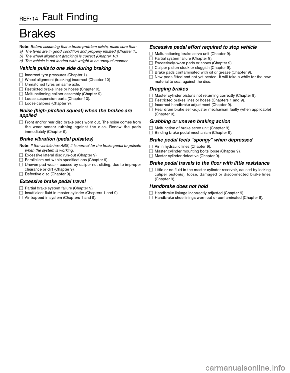
Brakes
Note:Before assuming that a brake problem exists, make sure that:
a) The tyres are in good condition and properly inflated (Chapter 1).
b) The wheel alignment (tracking) is correct (Chapter 10).
c) The vehicle is not loaded with weight in an unequal manner.
Vehicle pulls to one side during braking
m mIncorrect tyre pressures (Chapter 1).
m mWheel alignment (tracking) incorrect (Chapter 10)
m mUnmatched tyres on same axle.
m mRestricted brake lines or hoses (Chapter 9).
m mMalfunctioning caliper assembly (Chapter 9).
m mLoose suspension parts (Chapter 10).
m mLoose calipers (Chapter 9).
Noise (high-pitched squeal) when the brakes are
applied
m mFront and/or rear disc brake pads worn out. The noise comes from
the wear sensor rubbing against the disc. Renew the pads
immediately (Chapter 9).
Brake vibration (pedal pulsates)
Note:If the vehicle has ABS, it is normal for the brake pedal to pulsate
when the system is working.
m mExcessive lateral disc run-out (Chapter 9).
m mParallelism not within specifications (Chapter 9).
m mUneven pad wear - caused by caliper not sliding, due to improper
clearance or dirt (Chapter 9).
m mDefective disc (Chapter 9).
Excessive brake pedal travel
m
mPartial brake system failure (Chapter 9).
m mInsufficient fluid in master cylinder (Chapters 1 and 9).
m mAir trapped in system (Chapters 1 and 9).
Excessive pedal effort required to stop vehicle
m
mMalfunctioning brake servo unit (Chapter 9).
m mPartial system failure (Chapter 9).
m mExcessively-worn pads or shoes (Chapter 9).
m mCaliper piston stuck or sluggish (Chapter 9).
m mBrake pads contaminated with oil or grease (Chapter 9).
m mNew pads fitted and not yet seated. It will take a while for the new
material to seat against the disc.
Dragging brakes
m mMaster cylinder pistons not returning correctly (Chapter 9).
m mRestricted brakes lines or hoses (Chapters 1 and 9).
m mIncorrect handbrake adjustment (Chapter 9).
m mRear drum brake self-adjuster mechanism faulty (when applicable)
(Chapter 9).
Grabbing or uneven braking action
m mMalfunction of brake servo unit (Chapter 9).
m mBinding brake pedal mechanism (Chapter 9).
Brake pedal feels “spongy” when depressed
m
mAir in hydraulic lines (Chapter 9).
m mMaster cylinder mounting bolts loose (Chapter 9).
m mMaster cylinder defective (Chapter 9).
Brake pedal travels to the floor with little resistance
m
mLittle or no fluid in the master cylinder reservoir, caused by leaking
caliper piston(s), loose, damaged or disconnected brake lines
(Chapter 9).
Handbrake does not hold
m mHandbrake linkage incorrectly adjusted (Chapter 9).
m mHandbrake shoe linings worn out or contaminated (Chapter 9).
Page 216 of 228
REF•15
REF
Fault Finding
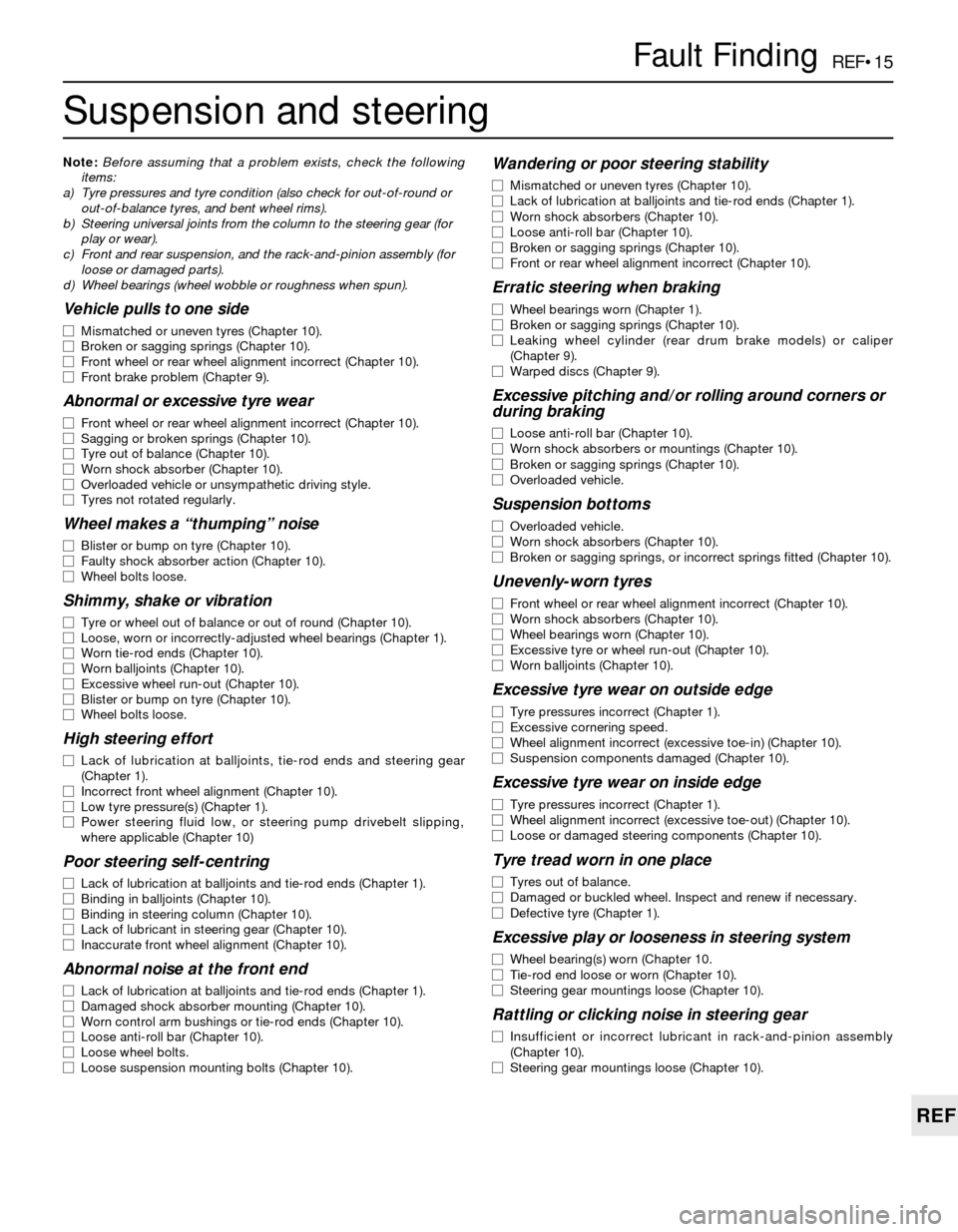
Suspension and steering
Note:Before assuming that a problem exists, check the following
items:
a) Tyre pressures and tyre condition (also check for out-of-round or
out-of-balance tyres, and bent wheel rims).
b) Steering universal joints from the column to the steering gear (for
play or wear).
c) Front and rear suspension, and the rack-and-pinion assembly (for
loose or damaged parts).
d) Wheel bearings (wheel wobble or roughness when spun).
Vehicle pulls to one side
m mMismatched or uneven tyres (Chapter 10).
m mBroken or sagging springs (Chapter 10).
m mFront wheel or rear wheel alignment incorrect (Chapter 10).
m mFront brake problem (Chapter 9).
Abnormal or excessive tyre wear
m
mFront wheel or rear wheel alignment incorrect (Chapter 10).
m mSagging or broken springs (Chapter 10).
m mTyre out of balance (Chapter 10).
m mWorn shock absorber (Chapter 10).
m mOverloaded vehicle or unsympathetic driving style.
m mTyres not rotated regularly.
Wheel makes a “thumping” noise
m
mBlister or bump on tyre (Chapter 10).
m mFaulty shock absorber action (Chapter 10).
m mWheel bolts loose.
Shimmy, shake or vibration
m
mTyre or wheel out of balance or out of round (Chapter 10).
m mLoose, worn or incorrectly-adjusted wheel bearings (Chapter 1).
m mWorn tie-rod ends (Chapter 10).
m mWorn balljoints (Chapter 10).
m mExcessive wheel run-out (Chapter 10).
m mBlister or bump on tyre (Chapter 10).
m mWheel bolts loose.
High steering effort
m
mLack of lubrication at balljoints, tie-rod ends and steering gear
(Chapter 1).
m mIncorrect front wheel alignment (Chapter 10).
m mLow tyre pressure(s) (Chapter 1).
m mPower steering fluid low, or steering pump drivebelt slipping,
where applicable (Chapter 10)
Poor steering self-centring
m mLack of lubrication at balljoints and tie-rod ends (Chapter 1).
m mBinding in balljoints (Chapter 10).
m mBinding in steering column (Chapter 10).
m mLack of lubricant in steering gear (Chapter 10).
m mInaccurate front wheel alignment (Chapter 10).
Abnormal noise at the front end
m
mLack of lubrication at balljoints and tie-rod ends (Chapter 1).
m mDamaged shock absorber mounting (Chapter 10).
m mWorn control arm bushings or tie-rod ends (Chapter 10).
m mLoose anti-roll bar (Chapter 10).
m mLoose wheel bolts.
m mLoose suspension mounting bolts (Chapter 10).
Wandering or poor steering stability
m
mMismatched or uneven tyres (Chapter 10).
m mLack of lubrication at balljoints and tie-rod ends (Chapter 1).
m mWorn shock absorbers (Chapter 10).
m mLoose anti-roll bar (Chapter 10).
m mBroken or sagging springs (Chapter 10).
m mFront or rear wheel alignment incorrect (Chapter 10).
Erratic steering when braking
m
mWheel bearings worn (Chapter 1).
m mBroken or sagging springs (Chapter 10).
m mLeaking wheel cylinder (rear drum brake models) or caliper
(Chapter 9).
m mWarped discs (Chapter 9).
Excessive pitching and/or rolling around corners or
during braking
m mLoose anti-roll bar (Chapter 10).
m mWorn shock absorbers or mountings (Chapter 10).
m mBroken or sagging springs (Chapter 10).
m mOverloaded vehicle.
Suspension bottoms
m
mOverloaded vehicle.
m mWorn shock absorbers (Chapter 10).
m mBroken or sagging springs, or incorrect springs fitted (Chapter 10).
Unevenly-worn tyres
m
mFront wheel or rear wheel alignment incorrect (Chapter 10).
m mWorn shock absorbers (Chapter 10).
m mWheel bearings worn (Chapter 10).
m mExcessive tyre or wheel run-out (Chapter 10).
m mWorn balljoints (Chapter 10).
Excessive tyre wear on outside edge
m
mTyre pressures incorrect (Chapter 1).
m mExcessive cornering speed.
m mWheel alignment incorrect (excessive toe-in) (Chapter 10).
m mSuspension components damaged (Chapter 10).
Excessive tyre wear on inside edge
m
mTyre pressures incorrect (Chapter 1).
m mWheel alignment incorrect (excessive toe-out) (Chapter 10).
m mLoose or damaged steering components (Chapter 10).
Tyre tread worn in one place
m
mTyres out of balance.
m mDamaged or buckled wheel. Inspect and renew if necessary.
m mDefective tyre (Chapter 1).
Excessive play or looseness in steering system
m
mWheel bearing(s) worn (Chapter 10.
m mTie-rod end loose or worn (Chapter 10).
m mSteering gear mountings loose (Chapter 10).
Rattling or clicking noise in steering gear
m
mInsufficient or incorrect lubricant in rack-and-pinion assembly
(Chapter 10).
m mSteering gear mountings loose (Chapter 10).
Page 221 of 228
REF•21
REF
Glossary of Technical Terms
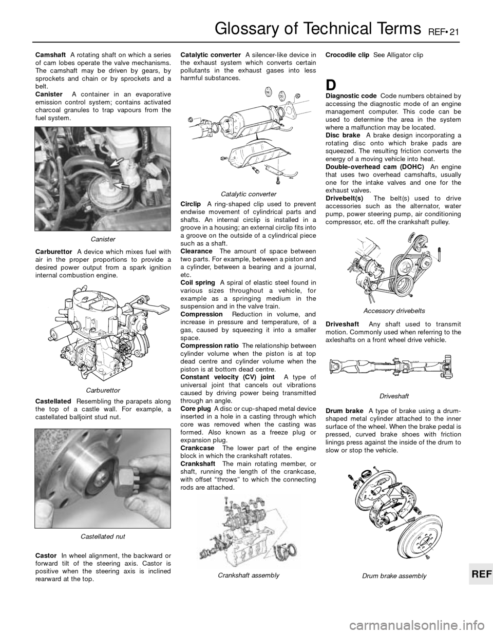
CamshaftA rotating shaft on which a series
of cam lobes operate the valve mechanisms.
The camshaft may be driven by gears, by
sprockets and chain or by sprockets and a
belt.
CanisterA container in an evaporative
emission control system; contains activated
charcoal granules to trap vapours from the
fuel system.
CarburettorA device which mixes fuel with
air in the proper proportions to provide a
desired power output from a spark ignition
internal combustion engine.
CastellatedResembling the parapets along
the top of a castle wall. For example, a
castellated balljoint stud nut.
CastorIn wheel alignment, the backward or
forward tilt of the steering axis. Castor is
positive when the steering axis is inclined
rearward at the top.Catalytic converterA silencer-like device in
the exhaust system which converts certain
pollutants in the exhaust gases into less
harmful substances.
CirclipA ring-shaped clip used to prevent
endwise movement of cylindrical parts and
shafts. An internal circlip is installed in a
groove in a housing; an external circlip fits into
a groove on the outside of a cylindrical piece
such as a shaft.
ClearanceThe amount of space between
two parts. For example, between a piston and
a cylinder, between a bearing and a journal,
etc.
Coil springA spiral of elastic steel found in
various sizes throughout a vehicle, for
example as a springing medium in the
suspension and in the valve train.
CompressionReduction in volume, and
increase in pressure and temperature, of a
gas, caused by squeezing it into a smaller
space.
Compression ratioThe relationship between
cylinder volume when the piston is at top
dead centre and cylinder volume when the
piston is at bottom dead centre.
Constant velocity (CV) jointA type of
universal joint that cancels out vibrations
caused by driving power being transmitted
through an angle.
Core plugA disc or cup-shaped metal device
inserted in a hole in a casting through which
core was removed when the casting was
formed. Also known as a freeze plug or
expansion plug.
CrankcaseThe lower part of the engine
block in which the crankshaft rotates.
CrankshaftThe main rotating member, or
shaft, running the length of the crankcase,
with offset “throws” to which the connecting
rods are attached.Crocodile clipSee Alligator clip
DDiagnostic codeCode numbers obtained by
accessing the diagnostic mode of an engine
management computer. This code can be
used to determine the area in the system
where a malfunction may be located.
Disc brakeA brake design incorporating a
rotating disc onto which brake pads are
squeezed. The resulting friction converts the
energy of a moving vehicle into heat.
Double-overhead cam (DOHC)An engine
that uses two overhead camshafts, usually
one for the intake valves and one for the
exhaust valves.
Drivebelt(s)The belt(s) used to drive
accessories such as the alternator, water
pump, power steering pump, air conditioning
compressor, etc. off the crankshaft pulley.
DriveshaftAny shaft used to transmit
motion. Commonly used when referring to the
axleshafts on a front wheel drive vehicle.
Drum brakeA type of brake using a drum-
shaped metal cylinder attached to the inner
surface of the wheel. When the brake pedal is
pressed, curved brake shoes with friction
linings press against the inside of the drum to
slow or stop the vehicle.
Castellated nut
Catalytic converter
Crankshaft assembly
Carburettor
Canister
Drum brake assembly
Accessory drivebelts
Driveshaft
Page 227 of 228

REF•27
REF
Index
R
Radiator - 3•3, 11•4
Radio - 12•4
Receiver-drier - 3•9
Regulator (voltage) - 5•10
Regulator (window) - 11•8
Relays - 12•2
Repair procedures - REF•8
Respraying - 11•3
Reversing light switch - 7B•4
Rocker arms - 2B•11
Rotor - 1•18
Routine maintenance and servicing- 1•1
et seq
Routine maintenance - air conditioning
system - 3•8
Routine maintenance - bodywork and
underframe - 11•1
Routine maintenance - hinges and locks -
11•4
Routine maintenance - interior trim - 11•2
Routine maintenance - upholstery and
carpets - 11•2
Rust holes in bodywork - 11•2
S
Safety first! - 0•5
Scalding - 0•5
Scratches in bodywork - 11•2
Screw threads and fastenings - REF•8
Seat belt - 11•9, REF•2
Seats - 11•9, REF•2
Selector lever - 7B•3, 7B•5
Selector shaft - 7A•2
Service Indicator (SI) board - 12•4
Service indicator light - 1•26
Servo - 9•2, 9•10, 9•11
Shock absorber - 1•21, 10•7, 10•8, 10•9,
REF•2, REF•3
Shoes - 9•7
Short-circuit - 12•2Silencer - 4•20
Slave cylinder - 8•3
Spares - REF•19
Spark plug - 1•17, 1•18
Speed sensors - 5•8
Springs - 10•7, 10•9, REF•3
Starter inhibitor - 7B•4
Starter motor - 5•12
Starter motor fault - REF•10
Starting system - 5•11
Steering box - 10•15
Steering column - 11•9, 12•3, REF•1
Steering gear - 10•12, 10•13, REF•3
Steering linkage - 10•14
Steering wheel - 10•16, REF•1
Stop-light switch - 9•13
Struts - 1•21, 10•6, 10•7
Sump - 2A•15
Supplemental Restraint System (SRS) -
12•8
Suspension and steering systems- 1•21,
1•22, 10•1et seq, REF•2, REF•3
Suspension and steering fault finding -
REF•15
Switches - 7B•4, 9•13, 12•3
T
Tailgate - 11•6
Tappets - 2B•11
Thermostat - 3•2
Thermotime switch - 4•17, 4•18
Throttle body - 4•16
Throttle linkage - 1•20
Throttle Position Sensor (TPS) - 6•3
Throttle positioner - 4•13, 4•14
Thrust arm - 10•5
Timing - 5•4
Timing belt - 1•26, 2A•8, 2A•9
Timing chain - 2A•6, 2A•8
Timing sensors - 6•4
Tools - REF•5, REF•7, REF•8
Top Dead Centre (TDC) for No 1 piston -
2A•3Torque converter - 7B•5
Towing - 0•8
Track rod ends - 10•13
Trailing arms - 10•10
Transmission - SeeManual transmission or
Automatic transmission
Trim - 11•2, 11•6
Tyres - 1•9, 1•14, 10•16, REF•4, REF•15
U
Underframe - 11•1
Universal joints - 8•8
Upholstery - 11•2
V
Vacuum hoses - 1•14
Vacuum servo - 9•10
Valve clearances - 1•19
Valve cover - 2A•4
Valves - 2B•10, 2B•11
Vehicle identification - REF•2, REF•19
Voltage checks - 12•1
Voltage regulator - 5•10
W
Washer fluid - 1•9
Water pump - 3•5
Weekly checks- 1•7et seq
Wheel alignment - 10•17
Wheel bearings - 10•8, 10•11, REF•3
Wheel changing - 0•8
Wheels - 10•16, REF•4
Windows - 11•8, 12•9
Windscreen - REF•1
Wiper blades - 1•23
Wiper motor - 12•7
Wiring diagrams- 12•9et seq
Working faclities - REF•7