wiring BMW 5 SERIES 2001 E39 Basic handsfree retrokit for updating various mobile phones Instalation Instruction Manual
[x] Cancel search | Manufacturer: BMW, Model Year: 2001, Model line: 5 SERIES, Model: BMW 5 SERIES 2001 E39Pages: 36, PDF Size: 1.5 MB
Page 26 of 36
EN/26Retrofit/Installation kit No. 65 90 0 028 873 84 64 25,805 (others see cover sheet)
Installation Instructions no. 01 29 0 029 541 01 29 0 029 544 Issue date: 04.2001
10. To install the basic wiring harness A and power supply wiring harness B in E39/2 cars
0
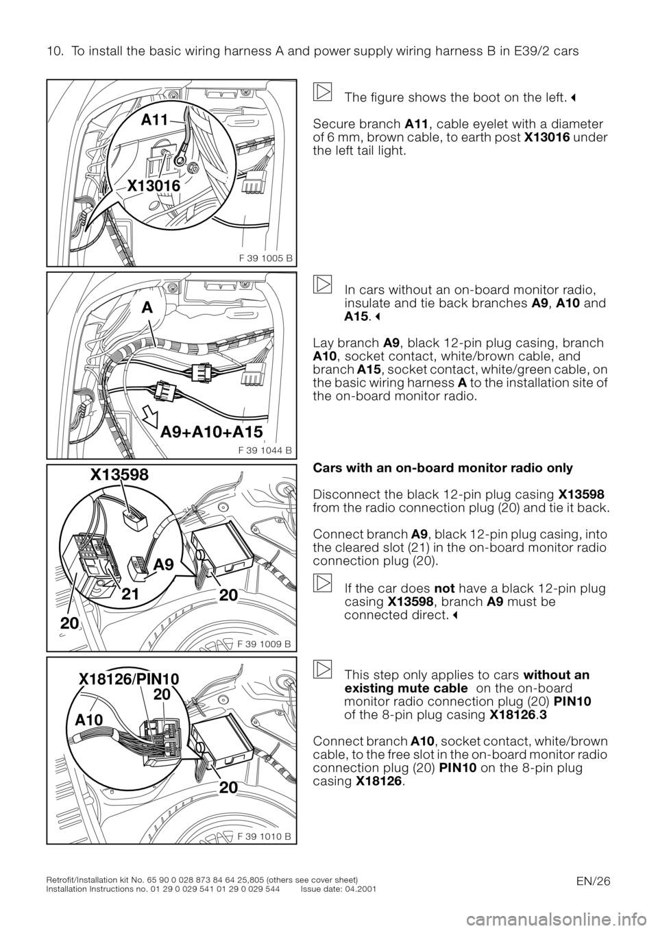
The figure shows the boot on the left."
Secure branch A11, cable eyelet with a diameter
of 6 mm, brown cable, to earth post X13016 under
the left tail light.
0
In cars without an on-board monitor radio,
insulate and tie back branches A9, A10 and
A15.
"
Lay branch A9, black 12-pin plug casing, branch
A10, socket contact, white/brown cable, and
branch A15, socket contact, white/green cable, on
the basic wiring harness A to the installation site of
the on-board monitor radio.
0Cars with an on-board monitor radio only
Disconnect the black 12-pin plug casing X13598
from the radio connection plug (20) and tie it back.
Connect branch A9, black 12-pin plug casing, into
the cleared slot (21) in the on-board monitor radio
connection plug (20).
If the car does not have a black 12-pin plug
casing X13598, branch A9 must be
connected direct.
"
0
This step only applies to cars without an
existing mute cable on the on-board
monitor radio connection plug (20) PIN10
of the 8-pin plug casing X18126.3
Connect branch A10, socket contact, white/brown
cable, to the free slot in the on-board monitor radio
connection plug (20) PIN10 on the 8-pin plug
casing X18126.
X13016A11
F 39 1005 B
A9+A10+A15
F 39 1044 B
A
X13598
20
20
A9
21
F 39 1009 B
F 39 1010 B
20 A10X18126/PIN10
20
Page 27 of 36
EN/27Retrofit/Installation kit No. 65 90 0 028 873 84 64 25,805 (others see cover sheet)
Installation Instructions no. 01 29 0 029 541 01 29 0 029 544 Issue date: 04.2001
10. To install the basic wiring harness A and power supply wiring harness B in E39/2 cars
0
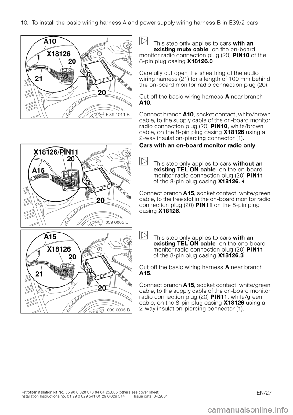
This step only applies to cars with an
existing mute cable on the on-board
monitor radio connection plug (20) PIN10 of the
8-pin plug casing X18126.3
Carefully cut open the sheathing of the audio
wiring harness (21) for a length of 100 mm behind
the on-board monitor radio connection plug (20).
Cut off the basic wiring harness A near branch
A10.
Connect branch A10, socket contact, white/brown
cable, to the supply cable of the on-board monitor
radio connection plug (20) PIN10, white/brown
cable, on the 8-pin plug casing X18126 using a
2-way insulation-piercing connector (1).
0Cars with an on-board monitor radio only
This step only applies to cars without an
existing TEL ON cable on the on-board
monitor radio connection plug (20) PIN11
of the 8-pin plug casing X18126.
"
Connect branch A15, socket contact, white/green
cable, to the free slot in the on-board monitor radio
connection plug (20) PIN11 on the 8-pin plug
casing X18126.
0
This step only applies to cars with an
existing TEL ON cable on the one-board
monitor radio connection plug (20) PIN11
of the 8-pin plug casing X18126.3
Cut off the basic wiring harness A near branch
A15.
Connect branch A15, socket contact, white/green
cable, to the supply cable of the on-board monitor
radio connection plug (20) PIN11, white/green
cable, on the 8-pin plug casing X18126 using a
2-way insulation-piercing connector (1).
20
F 39 1011 B
A10
211
20 X18126
039 0005 B
20 A15 X18126/PIN11
20
20
039 0006 B
A15
211
20 X18126
Page 28 of 36
EN/28Retrofit/Installation kit No. 65 90 0 028 873 84 64 25,805 (others see cover sheet)
Installation Instructions no. 01 29 0 029 541 01 29 0 029 544 Issue date: 04.2001
10. To install the basic wiring harness A and power supply wiring harness B in E39/2 cars
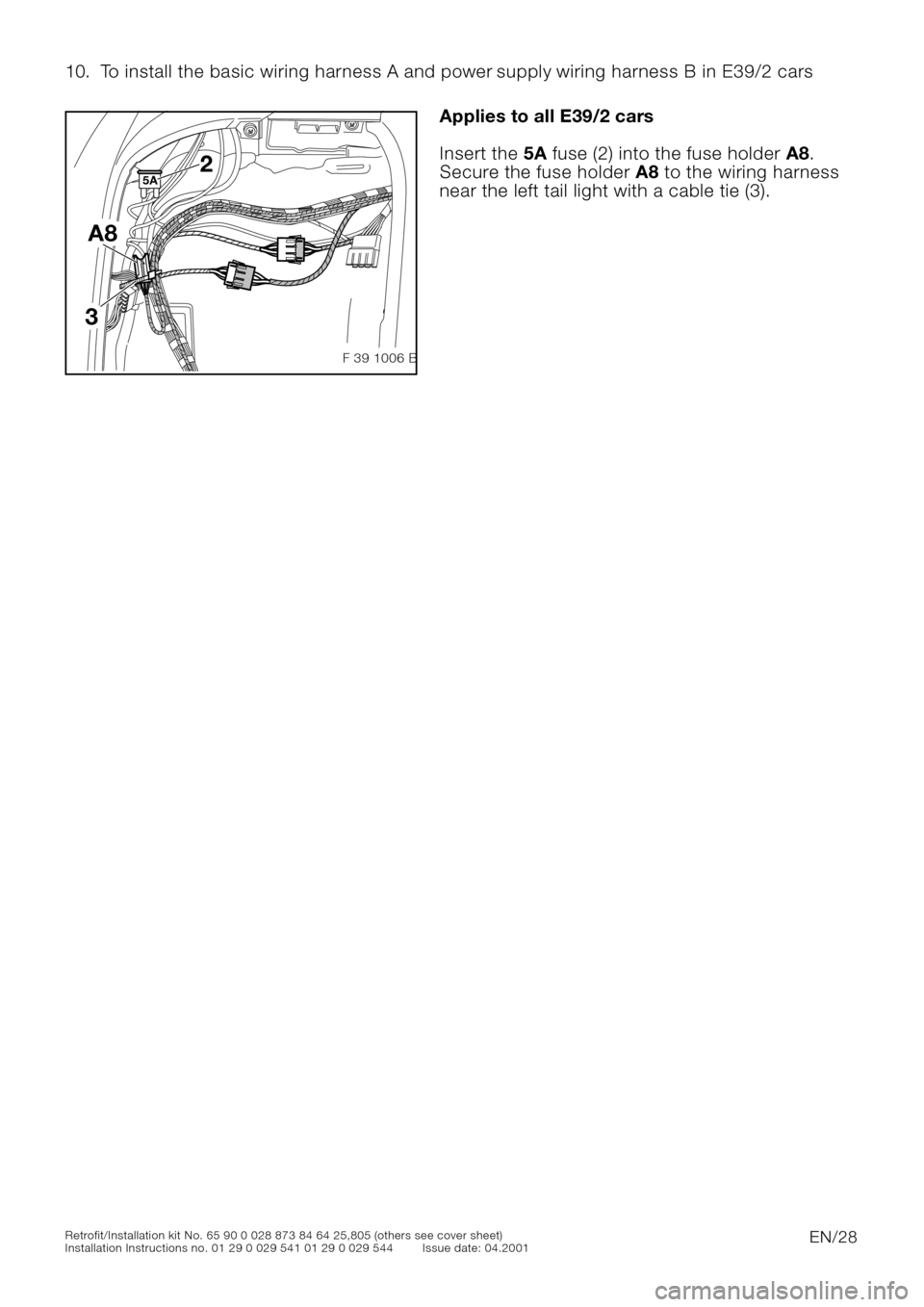
0Applies to all E39/2 cars
Insert the 5A fuse (2) into the fuse holder A8.
Secure the fuse holder A8 to the wiring harness
near the left tail light with a cable tie (3).
0
5A2
A8
3
F 39 1006 B
Page 30 of 36
EN/30Retrofit/Installation kit No. 65 90 0 028 873 84 64 25,805 (others see cover sheet)
Installation Instructions no. 01 29 0 029 541 01 29 0 029 544 Issue date: 04.2001
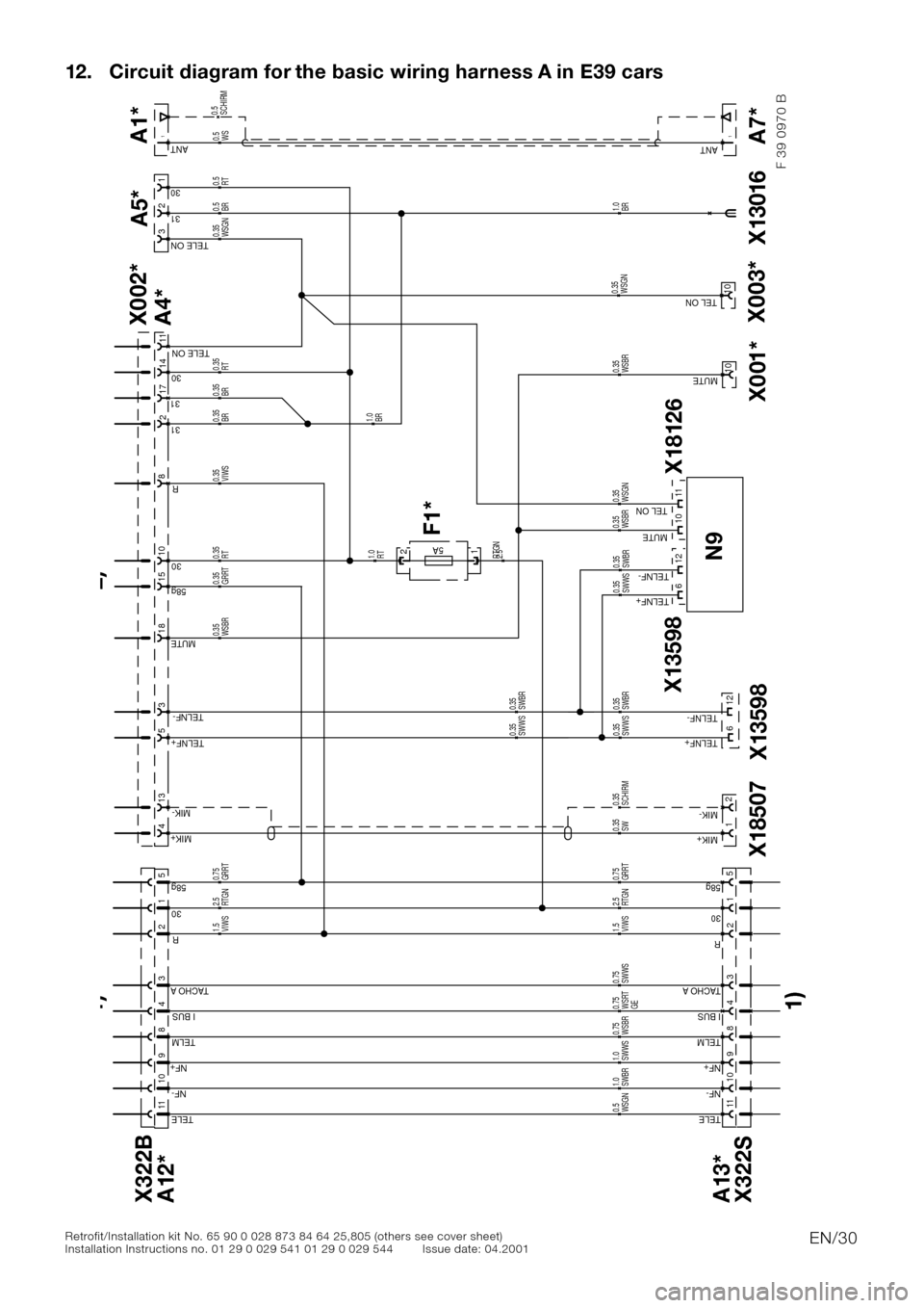
12. Circuit diagram for the basic wiring harness A in E39 cars
A5*
130
3TELE ON
231
SCHIRM 0.35
SW
0.35
5AF1*
12RT
1.0
X13016
BR
1.0
A7*1ANTA1*1ANT
SCHIRM
0.5
WS 0.5
A13*
X322S
11TELE
3TACHO A
2R
9NF+
10NF-
4I BUS
8TELM
130
558g
X322B
A12*
11TELE
3TACHO A
2R
9NF+
10NF-
4I BUS
8TELM
130
558gGRRT 0.75
RTGN
2.5
VIWS
1.5
WSGN 0.5
SWBR
1.0
SWWS
1.0
WSBR
0.75
WSRT
GE 0.75
SWWS 0.75
13MIK-
4MIK+
3
8 R
5TELNF+
TELNF-
231
18MUTE
1030
1558g
1731
1430
11TELE ON
SWWS 0.35
SWBR
0.35
SWWS
0.35
SWBR
0.35
WSBR
0.35
GRRT
0.35
RT
0.35
VIWS
0.35
X18507N9X18126 X13598
X13598
1MIK+
2MIK-
TELNF+
TELNF-
TELNF+
TELNF-
MUTE
X001*
10MUTE
GRRT 0.75
SWWS 0.35
SWBR
0.35
WSBR 0.35
WSBR
0.35
WSGN 0.35
RTGN
2.5
VIWS 1.5
RTGN
2.5
BR 1.0BR
0.35
BR
0.35
BR
0.5
RT
0.5
RT
0.35
A4* X002*
F 39 0970 B
10
TEL ONWSGN 0.3511
6
612
12
1)1) 2)
X003*
10WSGN 0.35TEL ON
Page 31 of 36

EN/31Retrofit/Installation kit No. 65 90 0 028 873 84 64 25,805 (others see cover sheet)
Installation Instructions no. 01 29 0 029 541 01 29 0 029 544 Issue date: 04.2001
12. Circuit diagram for the basic wiring harness A in E39 cars
Legend
F1*Floating fuse holder near the left tail light
X001*Socket contact
X002*Black 18-pin plug casing
X003*Socket contact
A1*Console aerial connector
A4*Black 18-pin socket casing
A5*Black 3-pin socket casing; cable compensator
A7*Boot aerial connector
A12*White 12-pin plug casing
A13*White 12-pin socket casing
N9Radio
X13016Cable eyelet, 6 mm in diameter; earth
X13598Black 12-pin plug casing
X181268-pin plug casing
X18507Black 3-pin connection plug; microphone
1)To standard wiring harness
2)To hands-free system wiring harness
The components and X designations marked with an asterisk (*) are only valid for this circuit
diagram.
All the other components and X designations correspond to BMW after-sales circuit diagrams
Colour abbreviations
BL = Blue OR = Orange
BR = Brown OR = Orange
GE = Yellow SW = Black
GN = Green VI = Violet
GR = Grey WS = White
Page 32 of 36
EN/32Retrofit/Installation kit No. 65 90 0 028 873 84 64 25,805 (others see cover sheet)
Installation Instructions no. 01 29 0 029 541 01 29 0 029 544 Issue date: 04.2001
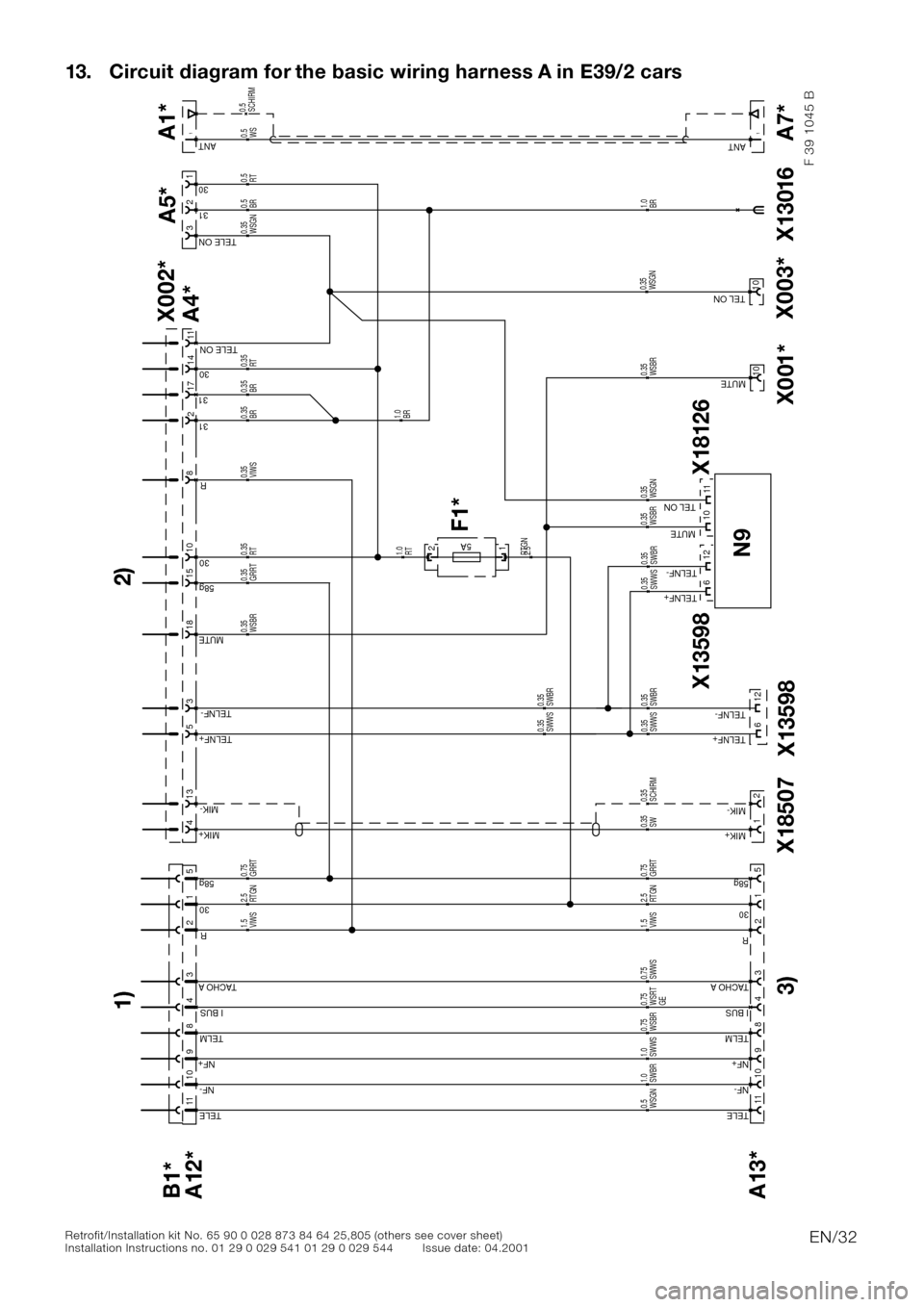
13. Circuit diagram for the basic wiring harness A in E39/2 cars
A5*
130
3TELE ON
231
SCHIRM 0.35
SW
0.35
5AF1*
12RT
1.0
X13016
BR
1.0
A7*1ANTA1*1ANT
SCHIRM
0.5
WS 0.5
A13*
11TELE
3TACHO A
2R
9NF+
10NF-
4I BUS
8TELM
130
558g
B1*
A12*
11TELE
3TACHO A
2R
9NF+
10NF-
4I BUS
8TELM
130
558gGRRT 0.75
RTGN
2.5
VIWS
1.5
WSGN 0.5
SWBR
1.0
SWWS
1.0
WSBR
0.75
WSRT
GE 0.75
SWWS 0.75
13MIK-
4MIK+
3
8 R
5TELNF+
TELNF-
231
18MUTE
1030
1558g
1731
1430
11TELE ON
SWWS 0.35
SWBR
0.35
SWWS
0.35
SWBR
0.35
WSBR
0.35
GRRT
0.35
RT
0.35
VIWS
0.35
X18507 3)N9X18126 X13598
X13598
1MIK+
2MIK-
TELNF+
TELNF-
TELNF+
TELNF-
MUTE
X001*
10MUTE
GRRT 0.75
SWWS 0.35
SWBR
0.35
WSBR 0.35
WSBR
0.35
WSGN 0.35
RTGN
2.5
VIWS 1.5
RTGN
2.5
BR 1.0BR
0.35
BR
0.35
BR
0.5
RT
0.5
RT
0.35
A4* X002*
F 39 1045 B
10
6
612
12
1) 2)
TEL ONWSGN 0.3511
X003*
10WSGN
0.35TEL ON
Page 33 of 36

EN/33Retrofit/Installation kit No. 65 90 0 028 873 84 64 25,805 (others see cover sheet)
Installation Instructions no. 01 29 0 029 541 01 29 0 029 544 Issue date: 04.2001
13. Circuit diagram for the basic wiring harness A in E39/2 cars
Legend
F1*Floating fuse holder near the left tail light
X001*Socket contact
X002*Black 18-pin plug casing
X003*Socket contact
A1*Console aerial connector
A4*Black 18-pin socket casing
A5*Black 3-pin socket casing; cable compensator
A7*Boot aerial connector
A12*White 12-pin plug casing
A13*White 12-pin socket casing
N9Radio
X322Black, 12-pin plug connector; audio hi-fi
X13016Cable eyelet, 6 mm in diameter; earth
X13598Black 12-pin plug casing
X181268-pin plug casing
X18507Black 3-pin connection plug; microphone
1)To power supply wiring harness B
2)To hands-free system wiring harness
3)To be tied back on the standard wiring harness
The components and X designations marked with an asterisk (*) are only valid for this circuit
diagram.
All the other components and X designations correspond to BMW after-sales circuit diagrams
Colour abbreviations
BL = Blue OR = Orange
BR = Brown OR = Orange
GE = Yellow SW = Black
GN = Green VI = Violet
GR = Grey WS = White
Page 34 of 36
EN/34Retrofit/Installation kit No. 65 90 0 028 873 84 64 25,805 (others see cover sheet)
Installation Instructions no. 01 29 0 029 541 01 29 0 029 544 Issue date: 04.2001
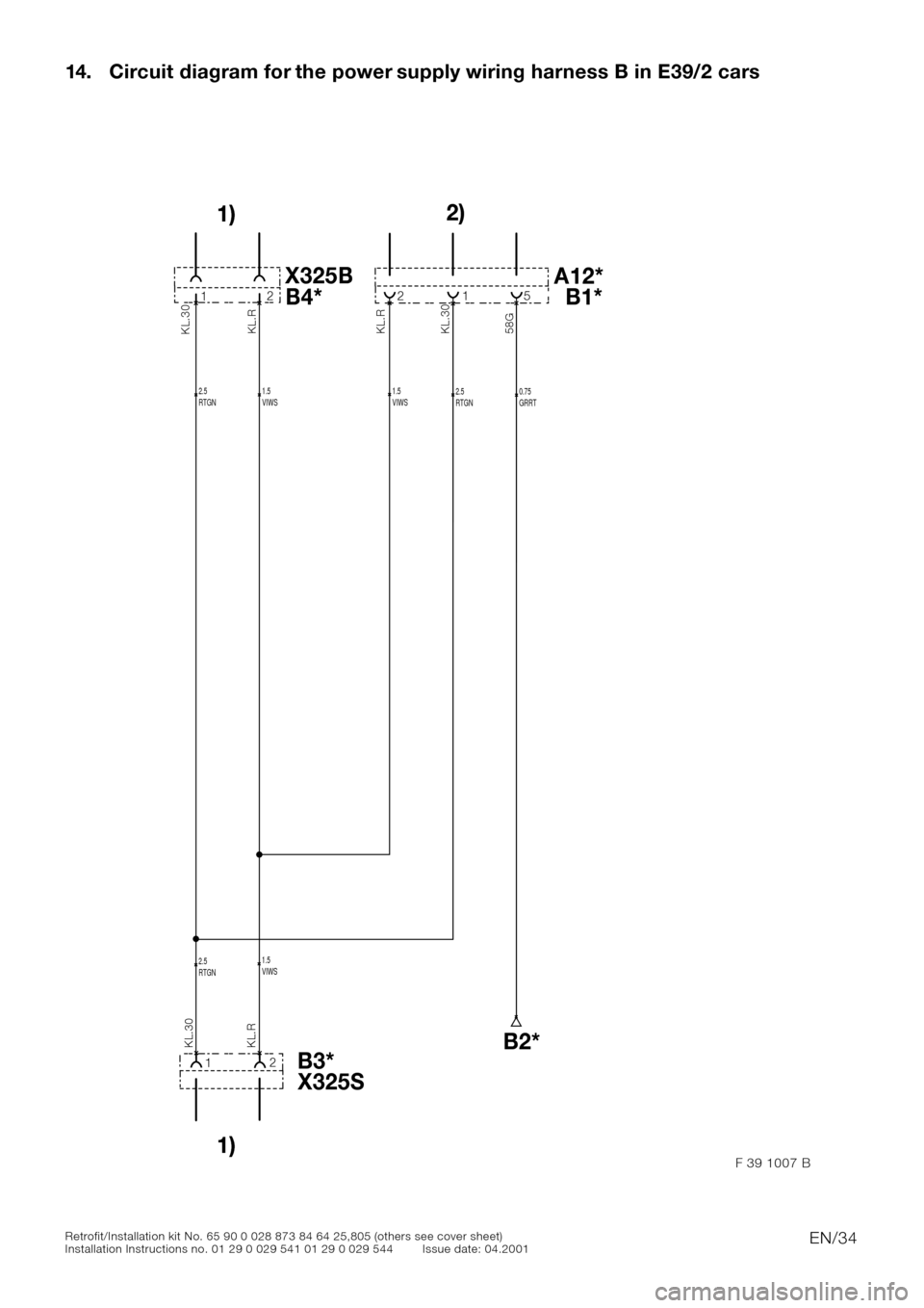
14. Circuit diagram for the power supply wiring harness B in E39/2 cars
VIWS 1.5RTGN
2.5GRRT
0.75RTGN
2.5
RTGN
2.5VIWS
1.5
VIWS
1.5
12
58GKL.30 KL.R
KL.R KL.30
5 1 2
21
KL.30
KL.R
1)
1)2)
A12* X325B
B1* B4*
X325S B3*B2*
F 39 1007 B
Page 35 of 36

EN/35Retrofit/Installation kit No. 65 90 0 028 873 84 64 25,805 (others see cover sheet)
Installation Instructions no. 01 29 0 029 541 01 29 0 029 544 Issue date: 04.2001
14. Circuit diagram for the power supply wiring harness B in E39/2 cars
Legend
A12*White 12-pin plug casing
B1*White 12-pin socket casing
B2*Open cable end; connect cable to supply cable X322 PIN5using a 2-way
insulation-piercing connector (1)
B3*Black 2-pin socket casing
B4*Black 2-pin plug casing
X325BBlack 2-pin socket casing
X325SBlack 2-pin plug casing
1)To standard wiring harness
2)To basic wiring harness A
The components and X designations marked with an asterisk (*) are only valid for this circuit
diagram.
All the other components and X designations correspond to BMW after-sales circuit diagrams
Colour abbreviations
BL = Blue OR = Orange
BR = Brown OR = Orange
GE = Yellow SW = Black
GN = Green VI = Violet
GR = Grey WS = White