coolant temperature BMW 5 SERIES 2002 E39 Model Yar Changes
[x] Cancel search | Manufacturer: BMW, Model Year: 2002, Model line: 5 SERIES, Model: BMW 5 SERIES 2002 E39Pages: 22, PDF Size: 1.05 MB
Page 15 of 22

15
2001 model year changes
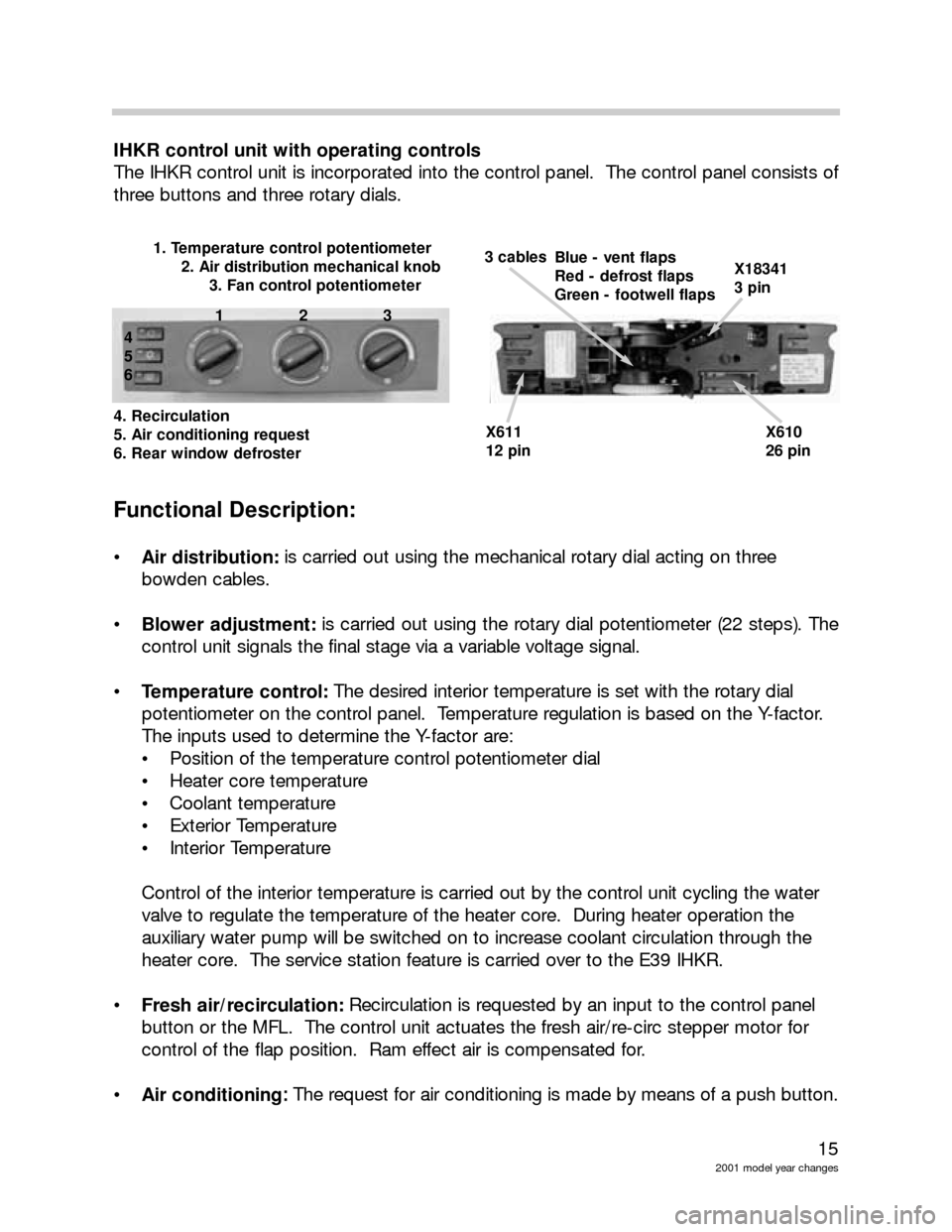
IHKR control unit with operating controls
The IHKR control unit is incorporated into the control panel. The control panel consists of
three buttons and three rotary dials.
Functional Description:
Air distribution:is carried out using the mechanical rotary dial acting on three
bowden cables.
Blower adjustment:is carried out using the rotary dial potentiometer (22 steps). The
control unit signals the final stage via a variable voltage signal.
Temperature control: The desired interior temperature is set with the rotary dial
potentiometer on the control panel. Temperature regulation is based on the Y-factor.
The inputs used to determine the Y-factor are:
Position of the temperature control potentiometer dial
Heater core temperature
Coolant temperature
Exterior Temperature
Interior Temperature
Control of the interior temperature is carried out by the control unit cycling the water
valve to regulate the temperature of the heater core. During heater operation the
auxiliary water pump will be switched on to increase coolant circulation through the
heater core. The service station feature is carried over to the E39 IHKR.
Fresh air/recirculation:Recirculation is requested by an input to the control panel
button or the MFL. The control unit actuates the fresh air/re-circ stepper motor for
control of the flap position. Ram effect air is compensated for.
Air conditioning: :
The request for air conditioning is made by means of a push button.
X611 X610
12 pin 26 pin
X18341
3 pinBlue - vent flaps
Red - defrost flaps
Green - footwell flaps3 cables1. Temperature control potentiometer
2. Air distribution mechanical knob
3. Fan control potentiometer
123
4
5
6
4. Recirculation
5. Air conditioning request
6. Rear window defroster
Page 17 of 22

17
2001 model year changes
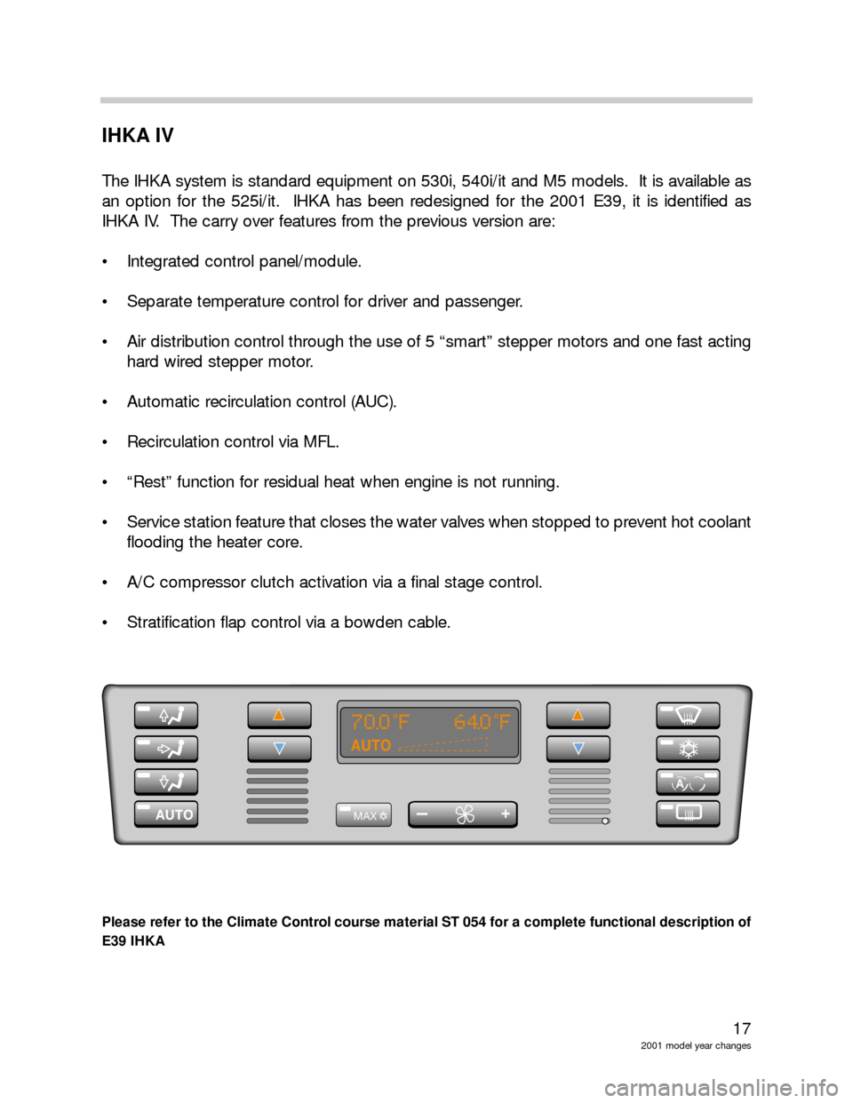
IHKA IV
The IHKA system is standard equipment on 530i, 540i/it and M5 models. It is available as
an option for the 525i/it. IHKA has been redesigned for the 2001 E39, it is identified as
IHKA IV. The carry over features from the previous version are:
Integrated control panel/module.
Separate temperature control for driver and passenger.
Air distribution control through the use of 5 “smart” stepper motors and one fast acting
hard wired stepper motor.
Automatic recirculation control (AUC).
Recirculation control via MFL.
“Rest” function for residual heat when engine is not running.
Service station feature that closes the water valves when stopped to prevent hot coolant
flooding the heater core.
A/C compressor clutch activation via a final stage control.
Stratification flap control via a bowden cable.
Please refer to the Climate Control course material ST 054 for a complete functional description of
E39 IHKA
70 0 F 640 F
-+AUTO
A
AUTO
MAX
Page 18 of 22

18
2001 model year changes
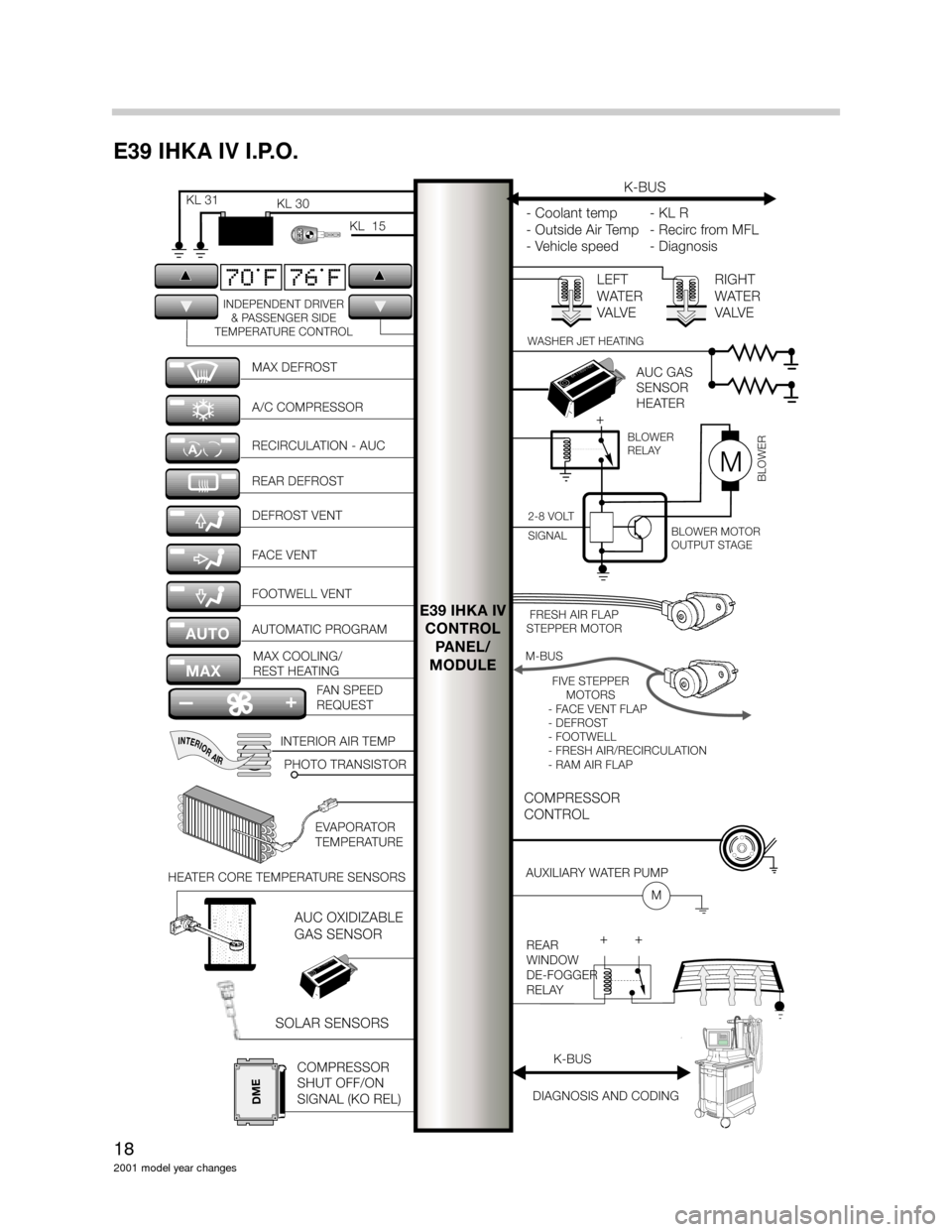
E39 IHKA IV I.P.O.
E39 IHKA IV
CONTROL
PANEL/
MODULE
MAX DEFROST
DEFROST VENT A/C COMPRESSOR
FACE VENT RECIRCULATION - AUC
FOOTWELL VENT REAR DEFROST
AUTOMATIC PROGRAM
MAX COOLING/
REST HEATING
FAN SPEED
REQUEST
INDEPENDENT DRIVER
& PASSENGER SIDE
TEMPERATURE CONTROL
HEATER CORE TEMPERATURE SENSORSEVAPORATOR
TEMPERATURE
COMPRESSOR
SHUT OFF/ON
SIGNAL (KO REL)
+ +REAR
WINDOW
DE-FOGGER
RELAY
AUTO
MAX
70 F 76 F
INTERIORAIR
BLOWER
RELAYBLOWER
RELAY
KL31KL 31KL30KL 30
KL15KL 15
M-BUSM-BUS
-FA C EVENTFLAP
-DEFROST
-FOOTWELL
-FRESHAIR/RECIRCULATION
-RAMAIRFLAP
- FACE VENT FLAP
- DEFROST
- FOOTWELL
- FRESH AIR/RECIRCULATION
- RAM AIR FLAP
FIVESTEPPER
MOTORSFIVE STEPPER
MOTORS
FRESHAIRFLAP
STEPPERMOTORFRESH AIR FLAP
STEPPER MOTOR
INTERIOR AIR TEMP
PHOTO TRANSISTOR
DIAGNOSIS AND CODING
6411839142064 118391420
6411839142064 118391420
COMPRESSOR
CONTROLCOMPRESSOR
CONTROL
AUXILIARYWATERPUMPAUXILIARY WATER PUMP
AUCGAS
SENSOR
HEATERAUC GAS
SENSOR
HEATER
K-BUSK-BUS
-Coolanttemp
-
OutsideAirTemp
-
Vehiclespeed
- Coolant temp
- Outside Air Temp
- Vehicle speed-KLR
-
RecircfromMFL
-
Diagnosis
-KLR
- Recirc from MFL
- Diagnosis
LEFT
WATER
VA LV ELEFT
WATER
VA LV ERIGHT
WATER
VA LV ERIGHT
WATER
VA LV E
-+
A
M
WASHER JET HEATING
2-8VOLT
SIGNAL2-8 VOLT
SIGNAL
MM
BLOWERMOTOR
OUTPUTSTAGEBLOWER MOTOR
OUTPUT STAGE
+
BLOWER
BMWDISB
M
WD
I
SBMWDISBMWDIS
DSC III
kjhsdfkhsdflkhsdlkfjhlkjghkg
lkdkfljdflkjdsfljdslfjldskjflkjdflk
ldsflsdfklhdsfhsdfhsdkhfkhsdf
kldjfkljdfkjdskfkjdskfjkljdfkldsfk
kjsdfkljsdfkdsfkjdsfkljsdfkjds
ldjsfklkjsdfkldsjfkdsjfkdsfkdfklk
K-BUS
DME
SOLAR SENSORSAUC OXIDIZABLE
GAS SENSOR
Page 20 of 22

20
2001 model year changes
REST Function
The REST function continues to operate as usual except that the MAX button has taken the
place of the REST button. Activation criteria continues to be:
Ignition “OFF” or in KL R.
“MAX” button pressed.
Outside temperature below 60
o F.
Coolant temperature above 80o C.
Battery voltage above 11.4V.
The REST feature operates as previously.
Diagnostics
The IHKA IV diagnosis has been upgraded to the E46 style diagnostic program.
Solar Sensor
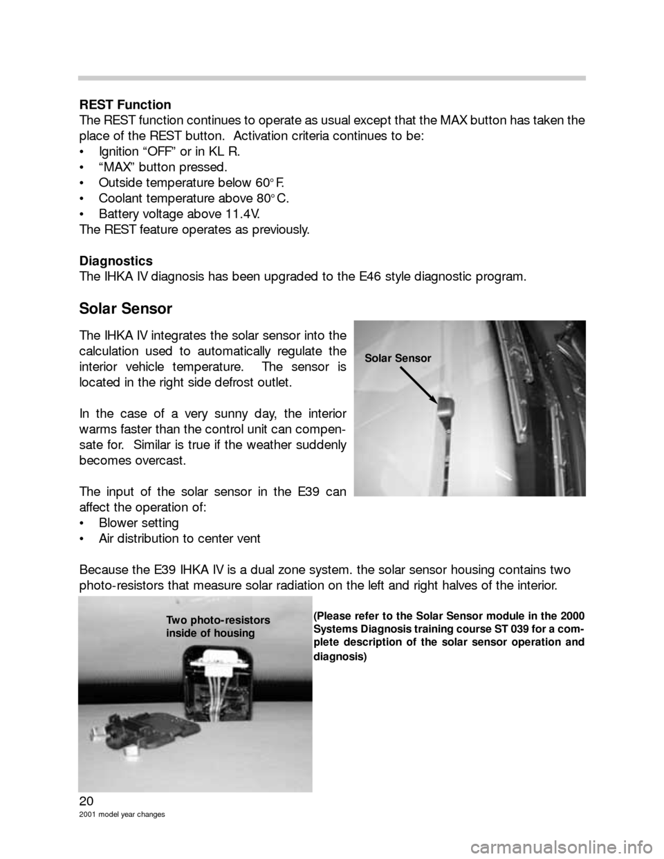
The IHKA IV integrates the solar sensor into the
calculation used to automatically regulate the
interior vehicle temperature. The sensor is
located in the right side defrost outlet.
In the case of a very sunny day, the interior
warms faster than the control unit can compen-
sate for. Similar is true if the weather suddenly
becomes overcast.
The input of the solar sensor in the E39 can
affect the operation of:
Blower setting
Air distribution to center vent
Because the E39 IHKA IV is a dual zone system. the solar sensor housing contains two
photo-resistors that measure solar radiation on the left and right halves of the interior.
(Please refer to the Solar Sensor module in the 2000
Systems Diagnosis training course ST 039 for a com-
plete description of the solar sensor operation and
diagnosis)
Solar Sensor
Two photo-resistors
inside of housing