Check control message BMW 5 SERIES 2014 F10 User Guide
[x] Cancel search | Manufacturer: BMW, Model Year: 2014, Model line: 5 SERIES, Model: BMW 5 SERIES 2014 F10Pages: 273, PDF Size: 5.73 MB
Page 92 of 273
General information
Steptronic Sport transmission: shift lights are
shown, when the SPORT+ driving program is
activated.
Manual transmission: shift lights are shown,
when the SPORT or SPORT+ driving program
is activated.
Switching on shift lightsSteptronic Sport transmission:1.Select Sport+ using the Driving Dynamics
Control.2.Activate the M/S manual mode of the
transmission.
Manual transmission:
1.Select SPORT or SPORT+ using the Driv‐
ing Dynamics Control.2.Deactivate DSC if needed.
Display in the instrument display
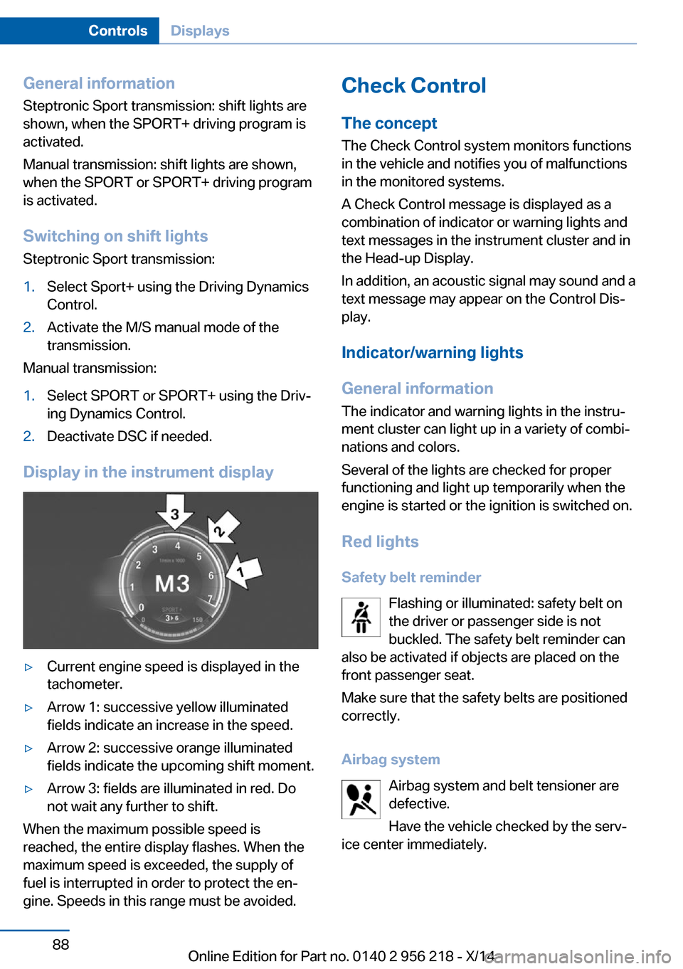
▷Current engine speed is displayed in the
tachometer.▷Arrow 1: successive yellow illuminated
fields indicate an increase in the speed.▷Arrow 2: successive orange illuminated
fields indicate the upcoming shift moment.▷Arrow 3: fields are illuminated in red. Do
not wait any further to shift.
When the maximum possible speed is
reached, the entire display flashes. When the
maximum speed is exceeded, the supply of
fuel is interrupted in order to protect the en‐
gine. Speeds in this range must be avoided.
Check Control
The concept The Check Control system monitors functions
in the vehicle and notifies you of malfunctions
in the monitored systems.
A Check Control message is displayed as a
combination of indicator or warning lights and
text messages in the instrument cluster and in
the Head-up Display.
In addition, an acoustic signal may sound and a text message may appear on the Control Dis‐
play.
Indicator/warning lights
General information
The indicator and warning lights in the instru‐
ment cluster can light up in a variety of combi‐
nations and colors.
Several of the lights are checked for proper
functioning and light up temporarily when the
engine is started or the ignition is switched on.
Red lights Safety belt reminder Flashing or illuminated: safety belt onthe driver or passenger side is not
buckled. The safety belt reminder can
also be activated if objects are placed on the
front passenger seat.
Make sure that the safety belts are positioned
correctly.
Airbag system Airbag system and belt tensioner aredefective.
Have the vehicle checked by the serv‐
ice center immediately.Seite 88ControlsDisplays88
Online Edition for Part no. 0140 2 956 218 - X/14
Page 95 of 273
For additional information, refer to Front fog
lights, refer to page 106.
High-beam Assistant High-beam Assistant is switched on.
High beams are activated and off auto‐
matically as a function of the traffic sit‐
uation.
For additional information, refer to High-beam
Assistant, refer to page 105.
Cruise control The system is switched on. It maintains
the speed that was set using the con‐
trol elements on the steering wheel.
Automatic Hold The vehicle is automatically held in
place when it is stationary.
On inclines, the system prevents the
vehicle from rolling backward when driving off.
For more information, see Automatic Hold, re‐
fer to page 74.
Blue lights
High beams High beams are activated.
For additional information, refer to High
beams, refer to page 76.
General lamps
Check Control At least one Check Control message is
displayed or is stored (symbol in dis‐
play).Text messages
Text messages in combination with a symbol
in the instrument cluster explain a Check Con‐ trol message and the meaning of the indicator
and warning lights.
Supplementary text messages
Additional information, such as on the cause of
an error or the required action, can be called up
via Check Control.
With urgent messages the added text will be
automatically displayed on the Control Display.
Symbols Depending on the Check Control message, the
following functions can be selected.▷ "Owner's Manual"
Display additional information about the
Check Control message in the Integrated
Owner's Manual.▷ "Service request"
Contact your service center.▷ "Roadside Assistance"
Contact Roadside Assistance.
Hiding Check Control messages
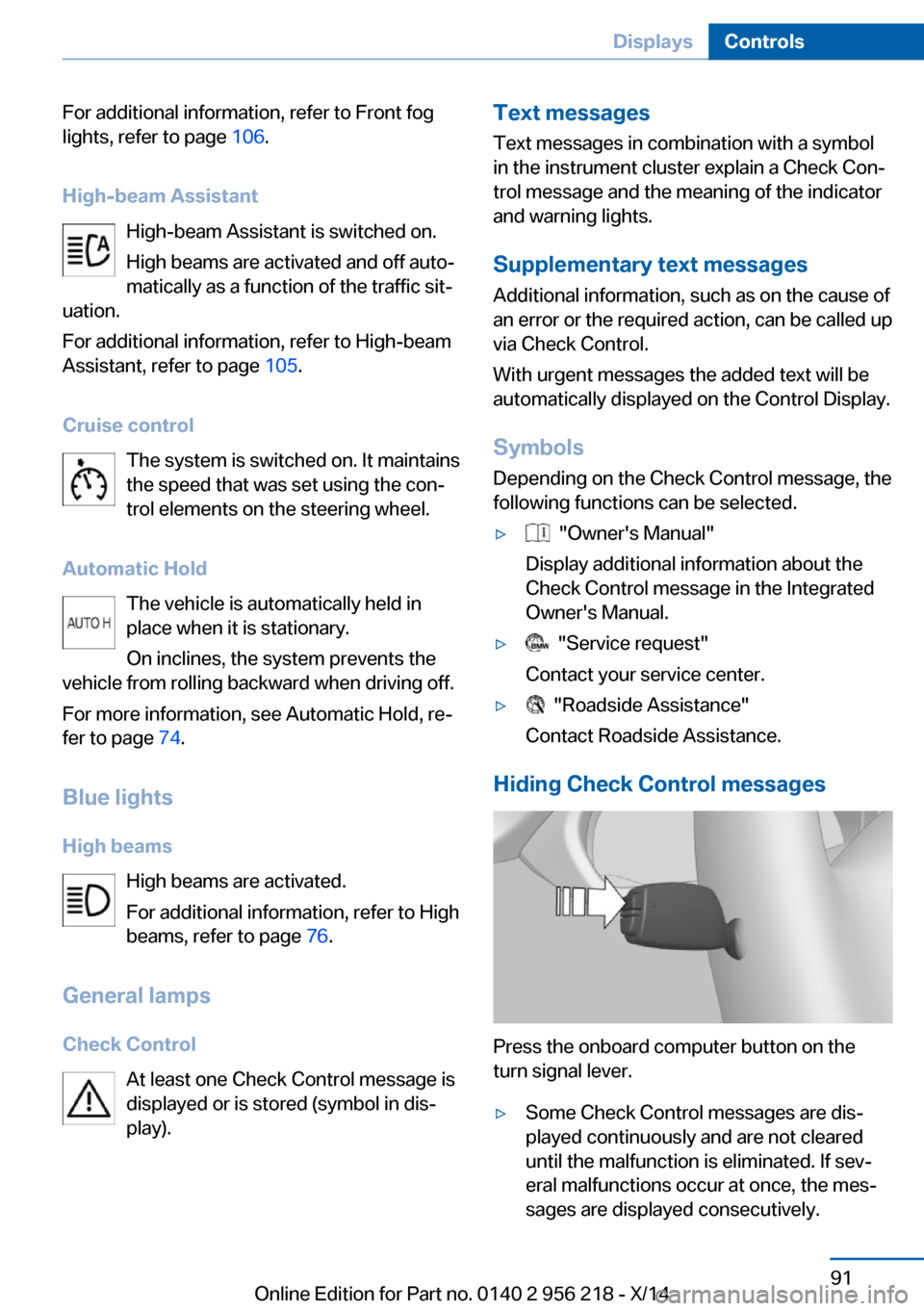
Press the onboard computer button on the
turn signal lever.
▷Some Check Control messages are dis‐
played continuously and are not cleared
until the malfunction is eliminated. If sev‐
eral malfunctions occur at once, the mes‐
sages are displayed consecutively.Seite 91DisplaysControls91
Online Edition for Part no. 0140 2 956 218 - X/14
Page 96 of 273
These messages can be faded for approx.
8 seconds. After this time, they are dis‐
played again automatically.▷Other Check Control messages are faded
automatically after approx. 20 seconds.
They are stored and can be displayed
again later.
Displaying stored Check Control
messages
On the Control Display:
1."Vehicle info"2."Vehicle status"3. "Check Control"4.Select the text message.
Messages after trip completion Special messages displayed while driving are
displayed again after the ignition is switched
off.
Fuel gauge Vehicle tilt position may cause
the display to vary.
Depending on the equipment
version, the arrow beside the
fuel pump symbol shows which
side of the vehicle the fuel filler flap is on.
Hints on refueling, refer to page 204.
Tachometer Always avoid engine speeds in the red warning
field. In this range, the fuel supply is inter‐
rupted to protect the engine.
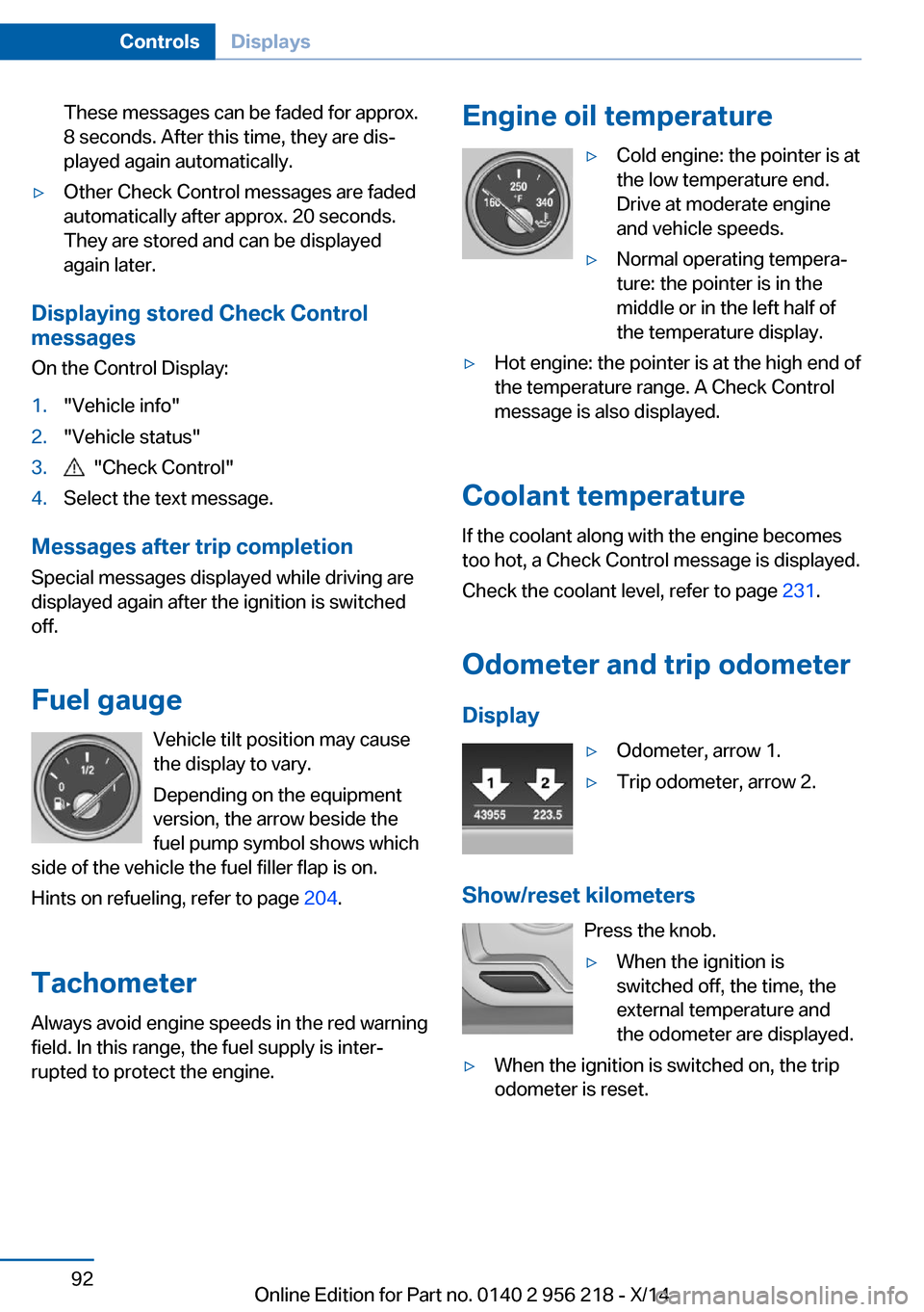
Engine oil temperature▷Cold engine: the pointer is at
the low temperature end.
Drive at moderate engine
and vehicle speeds.▷Normal operating tempera‐
ture: the pointer is in the
middle or in the left half of
the temperature display.▷Hot engine: the pointer is at the high end of
the temperature range. A Check Control
message is also displayed.
Coolant temperature
If the coolant along with the engine becomes
too hot, a Check Control message is displayed.
Check the coolant level, refer to page 231.
Odometer and trip odometer Display
▷Odometer, arrow 1.▷Trip odometer, arrow 2.
Show/reset kilometers Press the knob.
▷When the ignition is
switched off, the time, the
external temperature and
the odometer are displayed.▷When the ignition is switched on, the trip
odometer is reset.Seite 92ControlsDisplays92
Online Edition for Part no. 0140 2 956 218 - X/14
Page 97 of 273
External temperatureIf the indicator drops to
+37 ℉/+3 ℃ or lower, a signal
sounds.
A Check Control message is displayed.
There is an increased risk of ice on roads.
Ice on roads
Even at temperatures above
+37 ℉/+3 ℃, roads might be icy.
Therefore, drive carefully on bridges and
shaded roads, e.g., to avoid the increased risk
of an accident.◀
Time The time is displayed at the bot‐
tom of the instrument cluster.
Setting the time and time for‐
mat, refer to page 99.
Date The date is displayed in the
computer.
Setting the date and date for‐
mat, refer to page 100.
Range
Display With a low remaining range:▷A Check Control message is
displayed briefly.▷The remaining range is
shown on the computer.▷With a dynamic driving style - e.g., taking
curves aggressively - engine operation
might vary.The Check Control message appears continu‐
ously below a range of approx. 30 miles/50 km.
Refuel promptly
Refuel no later than at a range of
30 miles/50 km or engine operation might fail
and damage might occur.◀
Displaying the cruising range Depending on your vehicle's optional features,
the range can also be displayed as bar in the
instrument cluster.1."Settings"2."Instrument cluster"3."Additional indicators"
Range when destination guidance is
activated in the navigation system
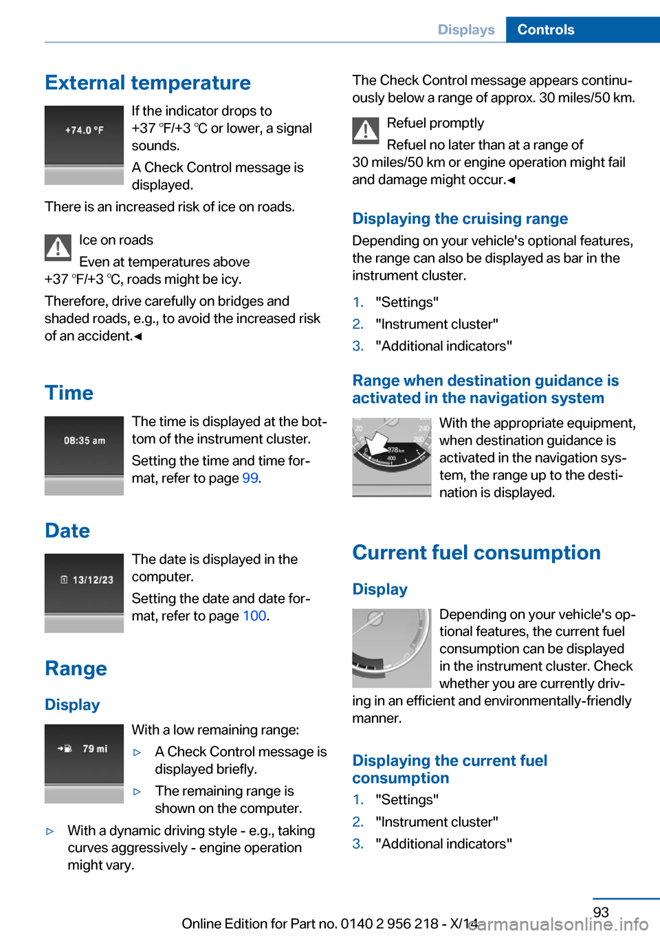
With the appropriate equipment,
when destination guidance is
activated in the navigation sys‐
tem, the range up to the desti‐
nation is displayed.
Current fuel consumption
Display Depending on your vehicle's op‐
tional features, the current fuel
consumption can be displayed
in the instrument cluster. Check
whether you are currently driv‐
ing in an efficient and environmentally-friendly
manner.
Displaying the current fuel
consumption
1."Settings"2."Instrument cluster"3."Additional indicators"Seite 93DisplaysControls93
Online Edition for Part no. 0140 2 956 218 - X/14
Page 105 of 273
Depending on the light conditions, the bright‐
ness settings may not be clearly visible.
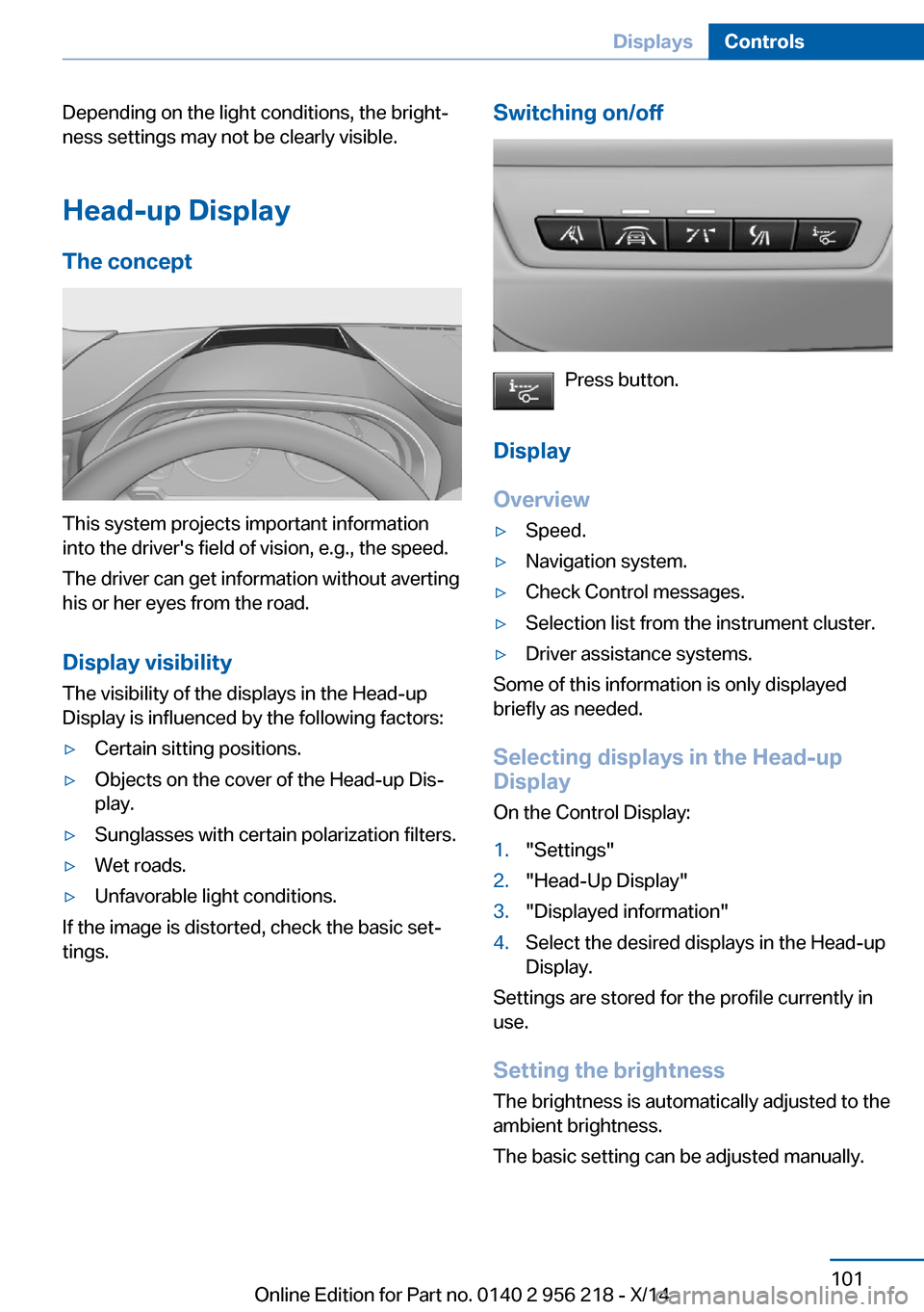
Head-up Display
The concept
This system projects important information
into the driver's field of vision, e.g., the speed.
The driver can get information without averting
his or her eyes from the road.
Display visibility The visibility of the displays in the Head-up
Display is influenced by the following factors:
▷Certain sitting positions.▷Objects on the cover of the Head-up Dis‐
play.▷Sunglasses with certain polarization filters.▷Wet roads.▷Unfavorable light conditions.
If the image is distorted, check the basic set‐
tings.
Switching on/off
Press button.
Display
Overview
▷Speed.▷Navigation system.▷Check Control messages.▷Selection list from the instrument cluster.▷Driver assistance systems.
Some of this information is only displayed
briefly as needed.
Selecting displays in the Head-up
Display
On the Control Display:
1."Settings"2."Head-Up Display"3."Displayed information"4.Select the desired displays in the Head-up
Display.
Settings are stored for the profile currently in
use.
Setting the brightness
The brightness is automatically adjusted to the
ambient brightness.
The basic setting can be adjusted manually.
Seite 101DisplaysControls101
Online Edition for Part no. 0140 2 956 218 - X/14
Page 109 of 273
ActivatingPosition of switch
with the ignition
switched on.
To avoid blinding oncoming traffic, the Adap‐
tive Light Control does not swivel to the driv‐
er's side when the vehicle is at a standstill.
The turning lights are automatically switched
on depending on the steering angle or the use
of turn signals.
When driving in reverse, the turning lights may
be automatically switched on regardless of the
steering angle.
Self-leveling headlights The self-leveling headlights compensate for
acceleration and braking operations in order
not to blind the oncoming traffic and to achieve
optimum illumination of the roadway.
Malfunction A Check Control message is displayed.
Adaptive Light Control is malfunctioning or has
failed. Have the system checked as soon as
possible.
High-beam Assistant
The concept When the low beams are activated, this system
automatically switches the high beams on and
off or suppresses the light in the areas that
blind oncoming traffic. The procedure is con‐
trolled by a camera on the front of the interior
rearview mirror. The assistant ensures that the
high beams are activated whenever the traffic
situation allows. The driver can intervene at
any time and reel the high beams on and off as
usual.
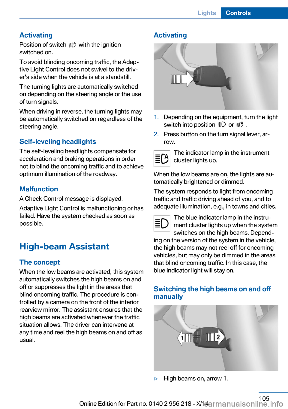
Activating1.Depending on the equipment, turn the light
switch into position
or .
2.Press button on the turn signal lever, ar‐
row.
The indicator lamp in the instrument
cluster lights up.
When the low beams are on, the lights are au‐
tomatically brightened or dimmed.
The system responds to light from oncoming
traffic and traffic driving ahead of you, and to
adequate illumination, e.g., in towns and cities.
The blue indicator lamp in the instru‐
ment cluster lights up when the system
switches on the high beams. Depend‐
ing on the version of the system in the vehicle, the high beams may not reel off for oncoming
vehicles, but may only be dimmed in the areas
that blind oncoming traffic. In this case, the blue indicator light will stay on.
Switching the high beams on and off manually
▷High beams on, arrow 1.Seite 105LightsControls105
Online Edition for Part no. 0140 2 956 218 - X/14
Page 115 of 273
factured. After installing a child seat, make
sure that the indicator lamp for the front-seat
passenger airbags lights up. This indicates
that the child seat has been detected and the
front-seat passenger airbags are not activated.
Strength of the driver's and front-seat
passenger airbag
The explosive power that activates driver's/
front passenger's airbags very much depends
on the positions of the driver's/front passeng‐
er's seat.
With a respective message appearing on Con‐
trol Display calibrate the front seats to keep
the accuracy of this function over the long-
term.
Calibrating the front seats A corresponding message appears on the
Control Display.1.Press the reel and move the respective
seat all the way forward.2.Press the reel forward again. The seat still
moves forward slightly.3.Readjust the seat to the desired position.
The calibration procedure is completed when
the message on the Control Display disap‐
pears.
If the message continues to be displayed, re‐
peat the calibration.
If the message does not disappear after a re‐
peat calibration, have the system checked as
soon as possible.
Unobstructed area of movement
Ensure that the area of movement of the
seats is unobstructed to avoid personal injury
or damage to objects.◀
Tire Pressure Monitor TPM
The concept The system monitors tire inflation pressure in
the four mounted tires. The system warns you
if there is a significant loss of pressure in one
or more tires. For this purpose, sensors in the
tire valves measure the tire inflation pressure
and tire temperature.
Hints Tire damage due to external factors
Sudden tire damage caused by external
circumstances cannot be recognized in ad‐
vance.◀
With use of the system observe further infor‐
mation found under Tire inflation pressure, re‐
fer to page 211.
Functional requirements
The system must have been reset with the
correct tire inflation pressure; otherwise, relia‐
ble signaling of tire inflation pressure loss is
not assured.
Reset the system after each adjustment of the
tire inflation pressure and after every tire or
wheel change.
Always use wheels with TPM electronics to
ensure that the system will operate properly.
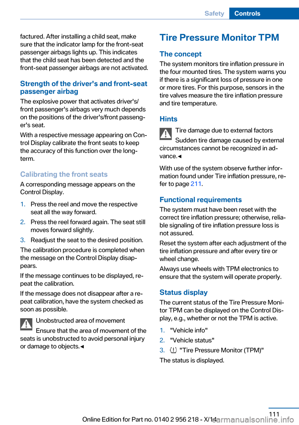
Status display The current status of the Tire Pressure Moni‐
tor TPM can be displayed on the Control Dis‐
play, e.g., whether or not the TPM is active.1."Vehicle info"2."Vehicle status"3. "Tire Pressure Monitor (TPM)"
The status is displayed.
Seite 111SafetyControls111
Online Edition for Part no. 0140 2 956 218 - X/14
Page 116 of 273
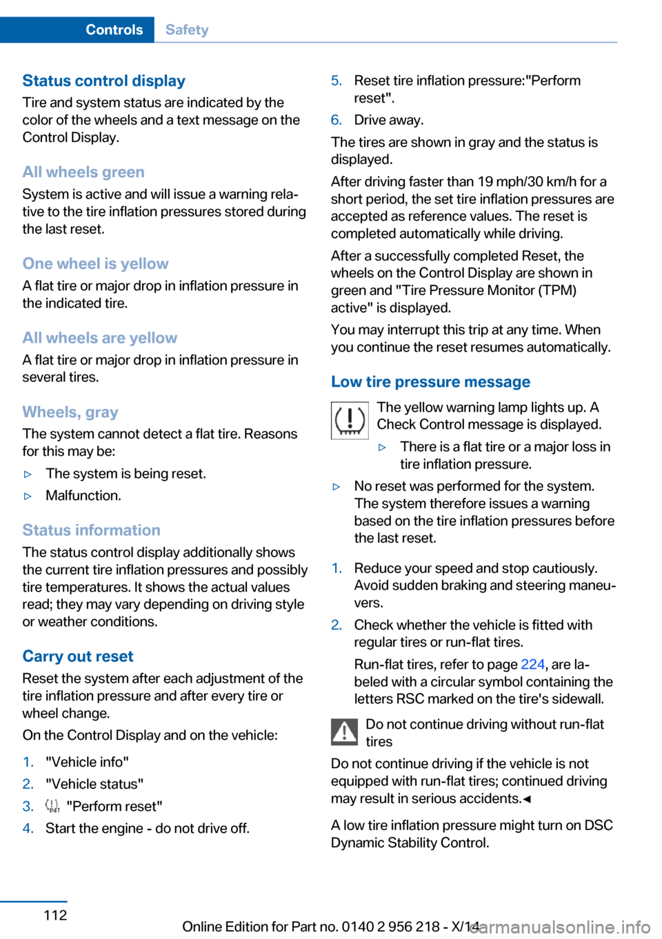
Status control displayTire and system status are indicated by the
color of the wheels and a text message on the
Control Display.
All wheels green System is active and will issue a warning rela‐
tive to the tire inflation pressures stored during
the last reset.
One wheel is yellow A flat tire or major drop in inflation pressure in
the indicated tire.
All wheels are yellow A flat tire or major drop in inflation pressure in
several tires.
Wheels, gray The system cannot detect a flat tire. Reasons
for this may be:▷The system is being reset.▷Malfunction.
Status information
The status control display additionally shows
the current tire inflation pressures and possibly
tire temperatures. It shows the actual values
read; they may vary depending on driving style or weather conditions.
Carry out reset
Reset the system after each adjustment of the
tire inflation pressure and after every tire or
wheel change.
On the Control Display and on the vehicle:
1."Vehicle info"2."Vehicle status"3. "Perform reset"4.Start the engine - do not drive off.5.Reset tire inflation pressure:"Perform
reset".6.Drive away.
The tires are shown in gray and the status is
displayed.
After driving faster than 19 mph/30 km/h for a
short period, the set tire inflation pressures are
accepted as reference values. The reset is
completed automatically while driving.
After a successfully completed Reset, the
wheels on the Control Display are shown in
green and "Tire Pressure Monitor (TPM)
active" is displayed.
You may interrupt this trip at any time. When
you continue the reset resumes automatically.
Low tire pressure message The yellow warning lamp lights up. A
Check Control message is displayed.
▷There is a flat tire or a major loss in
tire inflation pressure.▷No reset was performed for the system.
The system therefore issues a warning
based on the tire inflation pressures before
the last reset.1.Reduce your speed and stop cautiously.
Avoid sudden braking and steering maneu‐
vers.2.Check whether the vehicle is fitted with
regular tires or run-flat tires.
Run-flat tires, refer to page 224, are la‐
beled with a circular symbol containing the
letters RSC marked on the tire's sidewall.
Do not continue driving without run-flat
tires
Do not continue driving if the vehicle is not
equipped with run-flat tires; continued driving
may result in serious accidents.◀
A low tire inflation pressure might turn on DSC
Dynamic Stability Control.
Seite 112ControlsSafety112
Online Edition for Part no. 0140 2 956 218 - X/14
Page 117 of 273
Actions in the event of a flat tire
Normal tires1.Identify the damaged tire.
Do this by checking the air pressure in all
four tires.
If the tire inflation pressure in all four tires
is shown to be correct, it is possible that
the Tire Pressure Monitor did not perform
a reset. Then perform the reset.
If an identification is not possible, please
contact the service center.2.Fixing a flat tire, where applicable with the
Mobility System.
Run-flat tires
Maximum speed
You may continue driving with a damaged tire
at speeds up to 50 mph/80 km/h.
Continued driving with a flat tire
If continuing to drive with a damaged tire:
1.Avoid sudden braking and steering maneu‐
vers.2.Do not exceed a speed of 50 mph/80 km/h.3.Check the air pressure in all four tires at
the next opportunity.
If the tire inflation pressure in all four tires
is shown to be correct, it is possible that
the Tire Pressure Monitor did not perform
a reset. In that case, carry out a reset.
Possible driving distance with complete loss of
tire inflation pressure:
The possible driving distance after a loss of tire
inflation pressure depends on cargo load, driv‐
ing style and road conditions.
A vehicle with an average load has a possible
driving range of approx. 50 miles/80 km.
A vehicle with a damaged tire reacts differ‐
ently, e.g., it has reduced lane stability during
braking, a longer braking distance and different
self-steering properties. Adjust your driving
style accordingly. Avoid abrupt steering ma‐
neuvers or driving over obstacles, e.g., curbs,
potholes, etc.
Because the possible driving distance de‐
pends on how the vehicle is used during the
trip, the actual distance may be shorter or lon‐
ger depending on the driving speed, road con‐
ditions, external temperature, cargo load, etc.
Continued driving with a flat tire
Drive moderately and do not exceed a
speed of 50 mph/80 km/h.
Your car handles differently when you lose tire
inflation pressure, e.g., your lane stability is re‐
duced when braking, braking distances are
longer and the self-steering properties will
change.◀
Final tire failure
Vibrations or loud noises while driving
can indicate the final failure of a tire. Reduce
speed and stop; otherwise, pieces of the tire
could come loose and cause an accident. Do
not continue driving and contact your service
center.◀
Required tire inflation pressure check
message
A Check Control message is displayed in the
following situations▷The system has detected a wheel change,
but no reset was done.▷Inflation was not carried out according to
specifications.▷The tire inflation pressure has fallen below
the level of the last confirmation.
In this case:
▷Check the tire pressure and correct as
needed.▷Carry out a reset of the system after a tire
change.Seite 113SafetyControls113
Online Edition for Part no. 0140 2 956 218 - X/14
Page 118 of 273
System limits
The system does not function properly if a re‐
set has not been carried out, e.g., a flat tire is
reported though tire inflation pressures are
correct.
The tire inflation pressure depends on the
tire's temperature. Driving or exposure to the
sun will increase the tire's temperature, thus
increasing the tire inflation pressure. The tire
inflation pressure is reduced when the tire
temperature falls again. These circumstances
may cause a warning when temperatures fall
very sharply.
Malfunction The yellow warning lamp flashes and
then lights up continuously. A Check
Control message is displayed. No flat
tire or loss of tire inflation pressure can be de‐
tected.
Display in the following situations:▷A wheel without TPM electronics is fitted:
have the service center check it if needed.▷Malfunction: have the system checked by
your service center.▷TPM was unable to complete the reset.
Reset the system again.▷Interference through systems or devices
with the same radio frequency: after leav‐
ing the area of the interference, the system
automatically becomes active again.
Declaration according to NHTSA/
FMVSS 138 Tire Pressure Monitoring
System
Each tire, including the spare (if provided)
should be checked monthly when cold and in‐
flated to the inflation pressure recommended
by the vehicle manufacturer on the vehicle
placard or tire inflation pressure label. (If your
vehicle has tires of a different size than the size
indicated on the vehicle placard or tire inflation
pressure label, you should determine the
proper tire inflation pressure for those tires.)
As an added safety feature, your vehicle has
been equipped with a tire pressure monitoring
system (TPMS) that illuminates a low tire pres‐
sure telltale when one or more of your tires is
significantly under-inflated. Accordingly, when
the low tire pressure telltale illuminates, you
should stop and check your tires as soon as
possible, and inflate them to the proper pres‐
sure. Driving on a significantly under-inflated
tire causes the tire to overheat and can lead to
tire failure. Under-inflation also reduces fuel ef‐
ficiency and tire tread life, and may affect the
vehicle's handling and stopping ability. Please
note that the TPMS is not a substitute for
proper tire maintenance, and it is the driver's
responsibility to maintain correct tire pressure,
even if under-inflation has not reached the
level to trigger illumination of the TPMS low
tire pressure telltale. Your vehicle has also
been equipped with a TPMS malfunction indi‐
cator to indicate when the system is not oper‐
ating properly. The TPMS malfunction indica‐
tor is combined with the low tire pressure
telltale. When the system detects a malfunc‐
tion, the telltale will flash for approximately one
minute and then remain continuously illumi‐
nated. This sequence will continue upon sub‐
sequent vehicle start-ups as long as the mal‐
function exists. When the malfunction indicator
is illuminated, the system may not be able to
detect or signal low tire pressure as intended.
TPMS malfunctions may occur for a variety of
reasons, including the installation of replace‐
ment or alternate tires or wheels on the vehicle
that prevent the TPMS from functioning prop‐
erly. Always check the TPMS malfunction tell‐
tale after replacing one or more tires or wheels
on your vehicle to ensure that the replacement
or alternate tires and wheels allow the TPMS
to continue to function properly.Seite 114ControlsSafety114
Online Edition for Part no. 0140 2 956 218 - X/14