service indicator BMW 5 SERIES GRAN TURISMO 2015 Owners Manual
[x] Cancel search | Manufacturer: BMW, Model Year: 2015, Model line: 5 SERIES GRAN TURISMO, Model: BMW 5 SERIES GRAN TURISMO 2015Pages: 263, PDF Size: 5.06 MB
Page 64 of 263

Unbuckling the belt1.Hold the belt firmly.2.Press the red button in the belt buckle.3.Guide the belt back into its roll-up mecha‐
nism.
Safety belt reminder for driver's and
passenger's seat
The indicator lamp lights up and a sig‐
nal sounds. Make sure that the safety
belts are positioned correctly. The
safety belt reminder is active at speeds above
approx. 6 mph/10 km/h. It can also be activated
if objects are placed on the front passenger
seat.
Safety mode In critical situations, e.g., during full brake ap‐
plication, the front safety belts tighten auto‐
matically.
If the situation passes without an accident oc‐
curring, the belt tension relaxes.
If the belt tension does not loosen automati‐
cally, stop the vehicle and unbuckle the belt
using the red button in the buckle. Fasten the
belt before continuing on your trip.
Damage to safety belts
Wear and tear after accidents or when dam‐
aged otherwise:
Have the safety belts, including the safety belt
tensioners, replaced and have the belt anchors
checked.
Check and replace safety belts
This should only be done by your service
center; otherwise, this safety feature might not
work properly.◀
Front head restraints
Correctly adjusted head restraint
A correctly adjusted head restraint reduces the
risk of injury to cervical vertebrae in the event
of an accident.
Adjusting the head restraint
Adjust the head restraints of all occupied
seats properly; otherwise, there is an increased
risk of injury in an accident.◀
Height
Adjust the head restraint so that its center is
approximately at ear level.
Distance
Adjust the distance so that the head restraint
is as close as possible to the back of the head.
Active head restraint
In the event of a rear-end collision with a cer‐
tain severity, the active head restraint automat‐
ically reduces the distance from the head.
Reduced protective function▷Do not use seat or head restraint
covers.▷Do not hang objects, e.g., clothes hangers,
on the head restraints.▷Only attach accessories approved by BMW
to the seat or head restraint.
Otherwise, the protective function of the active
head restraint will be impaired and the per‐
sonal safety of the occupants will be endan‐
gered.◀
Wear and tear after accidents or when dam‐
aged otherwise:
Have the active headrest checked and if
needed replaced.
Seite 60ControlsAdjusting60
Online Edition for Part no. 01 40 2 954 285 - II/15
Page 89 of 263

▷Messages, e.g. Check Control, refer to
page 87.▷Current fuel consumption, refer to
page 93.▷Navigation display, see User's manual for
Navigation, Entertainment and Communi‐
cation.▷Range, refer to page 92.▷Status, Driving Dynamics Control, refer to
page 139.▷Service requirements, refer to page 93.▷Speed limit detection, refer to page 94.▷Time, refer to page 92.
Multifunctional instrument display
The concept
The instrument display is a variable display. In
the event of a program change, the display
rendition adapts to the respective program
through the Driving Dynamics Control. The
change of appearance can be deactivated on
the Control Display.Some of the displays in the instrument display
may differ from the way they are shown in this
Owner's Manual.
At a glance
1Fuel gauge 912Indicator/warning lights 883Speedometer4Variable displays5Tachometer 91
Selection lists 96
ECO PRO displays 1936Engine oil temperature 91Seite 85DisplaysControls85
Online Edition for Part no. 01 40 2 954 285 - II/15
Page 97 of 263
Displaying the cruising rangeDepending on your vehicle's optional features,
the range can also be displayed as bar in the
instrument cluster.1."Settings"2."Instrument cluster"3."Additional indicators"
With navigation system: range with destination guidance active
If respective equipment is fitted
and destination guidance is ac‐
tive, the remaining range is dis‐ played when the destination is
reached.
Current fuel consumption
Display Depending on your vehicle's op‐
tional features, the current fuel
consumption can be displayed
in the instrument cluster. Check
whether you are currently driv‐
ing in an efficient and environmentally-friendly
manner.
Displaying the current fuel
consumption
1."Settings"2."Instrument cluster"3."Additional indicators"
The bar display for the current fuel consump‐
tion is displayed in the instrument cluster.
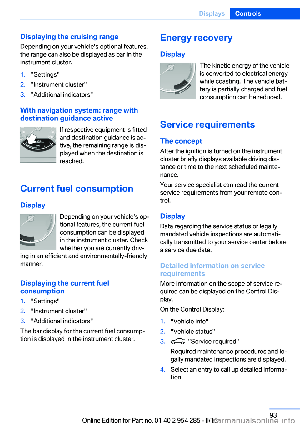
Energy recovery
Display The kinetic energy of the vehicle
is converted to electrical energy while coasting. The vehicle bat‐
tery is partially charged and fuel
consumption can be reduced.
Service requirements The concept
After the ignition is turned on the instrument
cluster briefly displays available driving dis‐
tance or time to the next scheduled mainte‐
nance.
Your service specialist can read the current
service requirements from your remote con‐
trol.
Display
Data regarding the service status or legally
mandated vehicle inspections are automati‐
cally transmitted to your service center before
a service due date.
Detailed information on service
requirements
More information on the scope of service re‐
quired can be displayed on the Control Dis‐
play.
On the Control Display:1."Vehicle info"2."Vehicle status"3. "Service required"
Required maintenance procedures and le‐
gally mandated inspections are displayed.4.Select an entry to call up detailed informa‐
tion.Seite 93DisplaysControls93
Online Edition for Part no. 01 40 2 954 285 - II/15
Page 98 of 263

SymbolsSym‐
bolsDescriptionNo service is currently required.The deadline for scheduled mainte‐
nance or a legally mandated inspec‐
tion is approaching.The service deadline has already
passed.
Entering appointment dates
Enter the dates for the required inspections.
Make sure that the vehicle's date and time are
set correctly.
On the Control Display:
1."Vehicle info"2."Vehicle status"3. "Service required"4."§ Vehicle inspection"5."Date:"6.Adjust the settings.7.Confirm.
The entered date is stored.
Automatic Service Request
Data regarding the service status or legally
mandated vehicle inspections are automati‐
cally transmitted to your service center before
a service due date.
You can check when your service center was
notified.
On the Control Display:
1."Vehicle info"2."Vehicle status"3.Open "Options".4."Last Service Request"Gear shift indicator
The conceptThe system recommends the most fuel effi‐
cient gear for the current driving situation.
Depending on the vehicle's features and coun‐
try version of the vehicle, the gear shift indica‐
tor is active in the manual mode of the Step‐
tronic transmission.
Suggestions to shift gear up or down are dis‐
played in the instrument cluster.
On vehicles without a gear shift indicator, the
engaged gear is displayed.
DisplaysExampleDescriptionFuel efficient gear is set.Shift into fuel efficient gear.
Speed limit detection
The concept
Speed limit detection
Speed limit detection uses a symbol in the
shape of a traffic sign to display the currently
detected speed limit. The camera in the area of
the interior rearview mirror detects traffic signs
at the edge of the road as well as variable over‐
head sign posts. Traffic signs with extra sym‐
bols for wet road conditions, etc. are also de‐
tected and compared with the vehicle's
onboard data, such as for the rain sensor, and
will be displayed depending on the situation.
The system takes into account the information
stored in the navigation system and also dis‐
plays speed limits present on routes without
signs.
Seite 94ControlsDisplays94
Online Edition for Part no. 01 40 2 954 285 - II/15
Page 119 of 263

reported though tire inflation pressures are
correct.
The tire inflation pressure depends on the
tire's temperature. Driving or exposure to the
sun will increase the tire's temperature, thus
increasing the tire inflation pressure. The tire
inflation pressure is reduced when the tire
temperature falls again. These circumstances
may cause a warning when temperatures fall
very sharply.
Malfunction The yellow warning lamp flashes and
then lights up continuously. A Check
Control message is displayed. No flat
tire or loss of tire inflation pressure can be de‐
tected.
Display in the following situations:▷A wheel without TPM electronics is fitted:
have the service center check it if needed.▷Malfunction: have the system checked by
your service center.▷TPM was unable to complete the reset.
Reset the system again.▷Interference through systems or devices
with the same radio frequency: after leav‐
ing the area of the interference, the system
automatically becomes active again.
Declaration according to NHTSA/
FMVSS 138 Tire Pressure Monitoring
System
Each tire, including the spare (if provided)
should be checked monthly when cold and in‐
flated to the inflation pressure recommended
by the vehicle manufacturer on the vehicle
placard or tire inflation pressure label. (If your
vehicle has tires of a different size than the size
indicated on the vehicle placard or tire inflation
pressure label, you should determine the
proper tire inflation pressure for those tires.)
As an added safety feature, your vehicle has
been equipped with a tire pressure monitoring
system (TPMS) that illuminates a low tire pres‐
sure telltale when one or more of your tires is
significantly under-inflated. Accordingly, when
the low tire pressure telltale illuminates, you
should stop and check your tires as soon as
possible, and inflate them to the proper pres‐
sure. Driving on a significantly under-inflated
tire causes the tire to overheat and can lead to
tire failure. Under-inflation also reduces fuel ef‐
ficiency and tire tread life, and may affect the
vehicle's handling and stopping ability. Please
note that the TPMS is not a substitute for
proper tire maintenance, and it is the driver's
responsibility to maintain correct tire pressure,
even if under-inflation has not reached the
level to trigger illumination of the TPMS low
tire pressure telltale. Your vehicle has also
been equipped with a TPMS malfunction indi‐
cator to indicate when the system is not oper‐
ating properly. The TPMS malfunction indica‐
tor is combined with the low tire pressure
telltale. When the system detects a malfunc‐
tion, the telltale will flash for approximately one
minute and then remain continuously illumi‐
nated. This sequence will continue upon sub‐
sequent vehicle start-ups as long as the mal‐
function exists. When the malfunction indicator
is illuminated, the system may not be able to
detect or signal low tire pressure as intended.
TPMS malfunctions may occur for a variety of
reasons, including the installation of replace‐
ment or alternate tires or wheels on the vehicle
that prevent the TPMS from functioning prop‐
erly. Always check the TPMS malfunction tell‐
tale after replacing one or more tires or wheels
on your vehicle to ensure that the replacement
or alternate tires and wheels allow the TPMS
to continue to function properly.
Intelligent Safety The conceptIntelligent Safety enables central operation of
the driver assistance system.
Depending on how the vehicle is equipped, In‐
telligent Safety consists of one or more sys‐Seite 115SafetyControls115
Online Edition for Part no. 01 40 2 954 285 - II/15
Page 143 of 263

Self-leveling suspensionThe concept The self-leveling suspension keeps the vehicle
height and ground clearance constant. The
height of the vehicle at the rear axle is main‐
tained at a predefined level under all load con‐
ditions.
The system ensures consistent comfort by
keeping spring travel constant in all driving sit‐
uations.
Malfunction
A Check Control message is displayed. The system is disrupted. Vehicle handling may be
altered and driving comfort may be noticeably
reduced. Visit your nearest service center.
Driving Dynamics Control The concept
The Driving Dynamics Control can be used to
adjust the driving dynamics of the vehicle. For
this purpose various programs are available for
selection that are activated via the two buttons
of the Driving Dynamics Control and the DSC
OFF-button.
Overview
Button in the vehicleOperating the programsPress buttonProgramDSC OFF
TRACTIONSPORT+
SPORT
COMFORT
COMFORT+
ECO PRO
Automatic program change
The system may automatically switch to COM‐
FORT in the following situations:
▷Failure of Integral Active Steering.▷Failure of Dynamic Damping Control.▷Failure of DSC Dynamic Stability Control.▷The vehicle has a flat tire.▷When activating cruise control in TRAC‐
TION or DSC OFF mode.
DSC OFF
Driving stability is limited during acceleration
and when driving in curves.
Stabilizing interventions by the Integral Active
Steering system are only performed by the
rear axle steering.
To increase vehicle stability, activate DSC
again as soon as possible.
Deactivating DSC: DSC OFF Press and hold this button but not lon‐
ger than approx. 10 seconds, until the
indicator lamp for DSC OFF lights up in the in‐
strument cluster and displays DSC OFF.
The DSC system is switched off.
Seite 139Driving stability control systemsControls139
Online Edition for Part no. 01 40 2 954 285 - II/15
Page 197 of 263

Avoid high engine speeds
As a rule: driving at low engine speeds lowers
fuel consumption and reduces wear.
If necessary, observe the gear shift indicator of
the vehicle, refer to page 94.
Use coasting
When approaching a red light, take your foot
off the accelerator and let the vehicle coast to
a halt.
For going downhill take your foot off the accel‐
erator and let the vehicle roll.
The flow of fuel is interrupted while coasting.
Switch off the engine during longer stops
Switch off the engine during longer stops, e.g.,
at traffic lights, railroad crossings or in traffic
congestion.
Auto Start/Stop function The Auto Start/Stop function of your vehicle
automatically switches off the engine during a
stop.
If the engine is switched off and then restarted
rather than leaving the engine running con‐
stantly, fuel consumption and emissions are
reduced. Savings can begin within a few sec‐
onds of switching off the engine.
In addition, fuel consumption is also deter‐
mined by other factors, such as driving style,
road conditions, maintenance or environmental
factors.
Switch off any functions that
are not currently needed
Functions such as seat heating and the rear
window defroster require a lot of energy andreduce the range, especially in city and stop-
and-go traffic.
Reel off these functions if they are not needed. The ECO PRO driving program supports the
energy conserving use of comfort features.
These functions are automatically deactivated
partially or completely.
Have maintenance carriedout
Have vehicles maintained regularly to achieve
optimal vehicle efficiency and operating life.
The maintenance should be carried out by
your service center.
Also note the BMW Maintenance System, refer
to page 223.
ECO PRO
The concept ECO PRO supports a driving style that saves
on fuel consumption. For this purpose, the en‐
gine control and comfort features, e. g. the cli‐
mate control output, are adjusted.
Under certain conditions the engine is auto‐
matically decoupled from the transmission in
the D selector lever position. The vehicle con‐
tinues traveling with the engine idling to re‐
duce fuel consumption. Selector lever position
D remains engaged.
In addition, context-sensitive instructions are
displayed to assist with an optimized fuel con‐
sumption driving style.
The achieved extended range is displayed in
the instrument cluster as bonus range.
Overview The system includes the following
EfficientDynamics functions and displays:▷ECO PRO bonus range, refer to page 194.Seite 193Saving fuelDriving tips193
Online Edition for Part no. 01 40 2 954 285 - II/15
Page 232 of 263

With LED headlights, all fron")
LED headlightsAt a glance1Corner-illuminating lights2Low-beams/high-beams3Parking lamp, daytime running lights4Turn signal5Side marker lights
Light-emitting diodes (LEDs)
With LED headlights, all front lights and side
indicators are designed with LED technology.
If an LED fails, switch on the front fog lights
and continue the trip with great care. Comply
with local regulations.
Contact your service center in the event of a
malfunction.
LED front fog lights
These front fog lights are made using LED
technology. Contact your service center in the
event of a malfunction.
Tail lights, bulb replacement
At a glance1Turn signal2Rear lamp3Inside brake lamp4Reversing lamp5Outside brake lamp
Turn signal, brake, tail, and license
plate lights
Follow general instructions, refer to page 225.
These lights feature LED technology.
Contact your service center in the event of a
malfunction.
Lights in the tailgate Follow general instructions, refer to page 225.
Access to the lights
1.Remove the four screws using the screw
driver from the onboard vehicle tool kit.Seite 228MobilityReplacing components228
Online Edition for Part no. 01 40 2 954 285 - II/15
Page 254 of 263

Computer, refer to On-boardcomputer 96
Condensation on win‐ dows 164
Condensation under the vehi‐ cle 188
Condition Based Service CBS 223
Configure driving mode 141
Confirmation signal 47
ConnectedDrive, see user's manual for Navigation, En‐
tertainment and Communi‐
cation
ConnectedDrive Services
Continued driving with a flat tire 111 , 114
Control Display 18
Control Display, settings 98
Controller 18
Control systems, driving sta‐ bility 134
Convenient opening with the remote control 37
Coolant 221
Coolant level 221
Coolant temperature 92
Cooling function 165
Cooling, maximum 165
Cooling system 221
Cornering light 103
Corrosion on brake discs 188
Cosmetic mirror 172
Courtesy lamps during un‐ locking 37
Courtesy lamps with the vehi‐ cle locked 38
Cruise control 149
Cruise control, active with Stop & Go 142
Cruise Control, refer to Active Cruise Control 142
Cruising range 92
Cupholder 180
Curb weight 245
Current fuel consumption 93 D
Damage, tires 209
Damping control, dy‐ namic 137
Data, technical 244
Date 92
Daytime running lights 103
Defrosting, refer to Windows, defrosting 164
Dehumidifying, air 165
Deleting personal data 24
Deletion of personal data 24
Destination distance 97
Digital clock 92
Dimensions 244
Dimmable exterior mirrors 64
Dimmable interior rearview mirror 64
Direction indicator, refer to Turn signals 77
Display, electronic, instru‐ ment cluster 84
Display in windshield 100
Display lighting, refer to In‐ strument lighting 105
Displays 85
Displays, cleaning 240
Disposal, coolant 222
Disposal, vehicle battery 230
Distance control, refer to PDC 151
Distance to destination 97
Divided screen view, split screen 23
Door lock 39
Door lock, refer to Remote control 34
Doors, Automatic Soft Clos‐ ing 40
Downhill control 136
Drive-off assistant 134
Drive-off assistant, refer to DSC 134
Driver assistance, refer to In‐ telligent Safety 115 Driving Assistant, refer to In‐
telligent Safety 115
Driving Dynamics Con‐ trol 139
Driving instructions, break- in 186
Driving mode 139
Driving notes, general 186
Driving stability control sys‐ tems 134
Driving tips 186
DSC Dynamic Stability Con‐ trol 134
DTC Dynamic Traction Con‐ trol 135
Dynamic Damping Con‐ trol 137
Dynamic Drive 137
Dynamic Stability Control DSC 134
Dynamic Traction Control DTC 135
E
ECO PRO 193
ECO PRO, bonus range 194
ECO PRO display 193
ECO PRO displays 86
ECO PRO driving mode 193
ECO PRO mode 193
ECO PRO Tip - driving in‐ struction 195
EfficientDynamics 195
Electronic displays, instru‐ ment cluster 84
Electronic oil measure‐ ment 218
Electronic Stability Program ESP, refer to DSC 134
Emergency detection, remote control 35
Emergency release, fuel filler flap 200
Emergency release, parking brake 76 Seite 250ReferenceEverything from A to Z250
Online Edition for Part no. 01 40 2 954 285 - II/15
Page 256 of 263

Headlight control, auto‐matic 103
Headlight courtesy delay fea‐ ture 103
Headlight courtesy delay fea‐ ture, remote control 47
Headlight courtesy delay fea‐ ture via remote control 39
Headlight flasher 78
Headlight glass 226
Headlights, care 238
Headlight washer system 78
Head restraints 54
Head restraints, front 60
Head restraints, rear 61
Head-up Display 100
Head-up Display, care 240
Heavy cargo, stowing 190
Height, vehicle 244
High-beam Assistant 104
High beams 78
High beams/low beams, refer to High-beam Assistant 104
Hill Descent Control HDC 136
Hills 188
Hill start assistant, refer to Drive-off assistant 134
Hints 6
Holder for beverages 180
Homepage 6
Hood 216
Horn 14
Hotel function, tailgate 43
Hot exhaust system 186
HUD Head-up Display 100
Hydroplaning 187
I Ice warning, see External temperature warning 92
Icy roads, see External tem‐ perature warning 92
Identification marks, tires 208 Identification number, see ve‐
hicle identification num‐
ber 9
iDrive 18
Ignition key, refer to Remote control 34
Ignition off 70
Ignition on 70
Indication of a flat tire 111 , 113
Indicator and alarm lamps, see Check Control 87
Indicator lamp, see Check Control 87
Individual air distribution 164
Individual settings, refer to Personal Profile 35
Inflation pressure, tires 204
Inflation pressure warning FTM, tires 110
Info display, refer to On- Board computer 96
Initialization, Integral Active Steering 138
Initialize, Tire Pressure Moni‐ tor TPM 113
Initializing, Flat Tire Monitor FTM 110
Instrument cluster 84
Instrument cluster, electronic displays 84
Instrument display, multifunc‐ tional 85
Instrument lighting 105
Integral Active Steering 138
Integrated key 34
Integrated Owner's Manual in the vehicle 29
Intelligent Emergency Re‐ quest 232
Intelligent Safety 115
Intensity, AUTO pro‐ gram 164
Interior equipment 170
Interior lights 105 Interior lights during unlock‐
ing 37
Interior lights with the vehicle locked 38
Interior motion sensor 48
Interior rearview mirror, auto‐ matic dimming feature 64
Interior rearview mirror, man‐ ually dimmable 64
Internet page 6
Interval display, service re‐ quirements 93
Interval mode 79
J
Jacking points for the vehicle jack 229
Joystick, Steptronic transmis‐ sion 81
Jump-starting 233
K
Key/remote control 34
Keyless Go, refer to Comfort Access 44
Key Memory, refer to Per‐ sonal Profile 35
Kickdown, Steptronic trans‐ mission 81
Knee airbag 107
L Lamp replacement, rear 228
Lane departure warning 128
Lane margin, warning 128
Language on Control Dis‐ play 99
Large tailgate via remote con‐ trol 38
Lashing eyes, securing cargo 190
LATCH child restraint sys‐ tem 68 Seite 252ReferenceEverything from A to Z252
Online Edition for Part no. 01 40 2 954 285 - II/15