emergency BMW 525i 1997 E39 User Guide
[x] Cancel search | Manufacturer: BMW, Model Year: 1997, Model line: 525i, Model: BMW 525i 1997 E39Pages: 1002
Page 908 of 1002
Downloaded from www.Manualslib.com manuals search engine
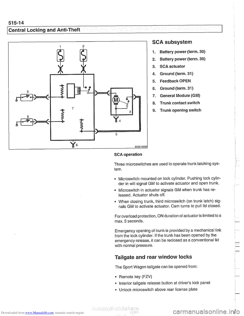
SCA subsystem
1. Battery power (term. 30)
2. Battery power (term. 30)
3. SCA actuator
4. Ground (term. 31)
5. Feedback OPEN
6. Ground (term. 31)
7. General Module (GM)
8. Trunk contact switch
9. Trunk opening switch
502515990
SCA operation
Three microswitches are used to operate trunk latching sys-
tem.
Microswitch mounted on lock cylinder. Pushing lock cylin-
der in will signal GM to activate actuator and open trunk.
Q Microswitch in actuator signals GM when trunlc has re-
leased. Actuator shuts off.
When closing trunk, third microswitch (on trunk latch) sig-
nals GM to activate actuator. Cam turns to pull lid closed.
Foroverload protection,
ON duration of actuator is limited to a
max.
5 seconds.
Emergency opening of trunk is provided by a mechanical link
from the lockcylinder.
If the trunlc has been opened by the
emergency release, it can be
reclosed as a conventional lid
with normal pressure.
Tailgate and rear window locks
The Sport Wagon tailgate can be opened from:
0 Remote lkey (FZV)
Interior tailgate release button at driver's lkick panel
Unlock microswitch above rear license plate
Page 915 of 1002
Downloaded from www.Manualslib.com manuals search engine
51 5-21
Central Locking and Anti-Theft
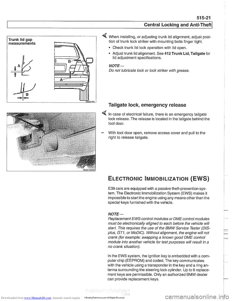
Trunk lid gap
measurements 4 When installing, or adjusting trunk lid alignment, adjust posi-
tion of trunk
loclc striker with mounting bolts finger tight.
* Check trunk lid loclc operation with lid open.
Adjust trunk lid alignment. See
412 Trunk Lid, Tailgate for
lid adjustment specifications.
NOTE-
Do not lubricate lock or lock striker with grease.
Tailgate lock, emergency release
4 In case of electrical failure, there is an emergency tailgate
loclk release. The release is located in the tailgate behind the
tool door.
- With tool door open, remove access cover and pull to the
right to release tailgate.
ELECTRONIC ~MMOBILIZATION (EWS)
E39 cars are equipped with a passive theft-prevention sys-
tem. The Electronic Immobilization System (EWS) makes it
impossible to
startthe engine using any means other than the
special lkeys furnished with the vehicle.
NOTE-
Replacement EWS control modules or DME control modules
must be electronically aligned to each before the vehicle will
start. This requires the use of the BMW Service Tester
(DIS-
plus, GT1, or MoDiC). Without alignment, the engine will not
crank (for example: swapping a
known good DME control
module into another vehicle for test purposes will result in a
no crank situation).
In the EWS system, the ignition key is embedded with
acom-
puter chip (EEPROM) and coded. The key communicates
with the vehicle using a transponder in the lkey and a ring an-
tenna surrounding the steering lock cylinder. Up to
6 replace-
ment keys are permissible. Only an authorized
BMW dealer
can provide replacement keys.
Page 920 of 1002
Downloaded from www.Manualslib.com manuals search engine
51 5-26
Central Locking and Anti-Theft
Interior sensor UIS (2000 and later models)
The
UIS system uses ultrasonic sound waves instead of elec-
tromagnetic waves. Ultrasonic sound waves are less suscep-
tible to magnetic interference.
Every time the DWA system is armed, the sensor adapts to
whatever objects might be stationary in the interior. The sen-
sor emits ultrasonic waves in a programmed timed cycle. It re-
ceives echoes of the emitted waves. The
UIS amplifies the
received sound wave signals and compares them to the ech-
oes of the transmitted waves. The
UIS also checits the incom-
ing echoes for background hiss (wind noise through a
partially open window) and adapts for this.
If the echoes are consistently similar, no movement is de-
tected.
If the echoes are altered, (inconsistent), the UIS deter-
mines motion in the interior compartment.
If motion is detected, the
UIS changes to a constant cycle
and the echo is compared again.
If the inconsistency is still present the
UIS sends the acti-
vate siren signal to the GM.
Glass breakage sensors
The doorwindows are monitored by inductive sensors mount-
ed on the inside of the door behind the trim panel. A closed
window is recognized by a magnetic plate
on the glass lining
up with the sensor. If the glass is broken, the plate falls away
and the signal from the sensor changes. This causes the GM
to activate the alarm.
Emergency disarming
- An emergency procedure is provided to cancel the DWA in
the event that a fault occurs within the system. The procedure
is as follows:
Driver's door mechanically
unloclted and open within 30
seconds. This will cause triggering of alarm.
All doors closed.
Ignition switch turned to
KL R (ACCESSORY). LED indica-
tor will come on.
- After 10 minutes, alarm is disarmed
Page 929 of 1002
Downloaded from www.Manualslib.com manuals search engine
540 Sunroof
General . . . . . . . . . . . . . . . . . . . . . . . . . . . ,540-2
Sunroof Adjustments. . . . . . . . . . . . . . . .540-2
Sunroof electronic controls, initializing . . . . ,540-2
Sunroof, normalization. . . . . . . . . . . . . . . . . ,540-3
Sunroof, characteristic curve . . . . . . . . . . . .540-3
Sunroof panel, emergency closing . . . . . . . ,540-4
Sunroof, adiustino . . . . . . . . . . . . . . . . . . . . ,540-5
~unroofwitil steel roof panel, adjusting . . . ,540-5
Sunroof with glass roof panel, adjusting . . . ,540-7
Sunroof Components . . . . . . . . . . . . . . 540-8
Sunroof components (glass)
. . . . . . . . . . . . 540-8
Sunroof panel, removing and
installing (steel or glass)
. . . . . . . . . . . . . . . 540-8
Sunroof panel gasket, replacing
(steel or glass)
. . . . . . . . . . . . . . . . . . . . . . . 540-9
Sunroof motor, replacing
. . . . . . . . . . . . . . 540-10
Page 932 of 1002
Downloaded from www.Manualslib.com manuals search engine
-.
Sunroof
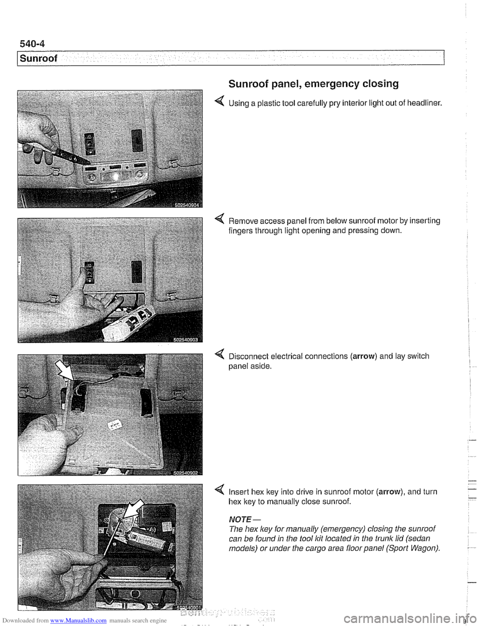
Sunroof panel, emergency closing
4 Using a plastic tool carefully pry interior light out of headliner.
4 Remove access panel from below sunroof motor by inserting
fingers through light opening and pressing down.
4 Disconnect electrical connections (arrow) and lay switch
panel aside.
4 Insert hex ltey into drive in sunroof motor (arrow), and turn
hex ltey to manually close sunroof.
NOTE-
The hex ley for manually (emergency) closing the sunroof
can be found in the tool
Itit located in the trunk lid (sedan
models) or under the cargo area floor panel (Sport Wagon).
Page 991 of 1002
Downloaded from www.Manualslib.com manuals search engine
INDEX 'tl
WARNING
Your common sense, good
judgemenl, and general alertness are
crucial to sale and successiul service
worlr. Belore attempting any work on
your
BMM be sure lo read 001
General Warnings and Cautions
and the
copyriglll page at the front 01
the manual. Review these warnings
and
caulions each lime you prepare
lo work on your BMW. Please also
read any warnings and cautions that
accompany
tile procedures in the
manual.
312-way valve (running losses)
see Fuel tank
Abbreviations, commonly used 600-14
ABS (antilock brake system)
see
Bral(es
A/C air distribution motors
see stepper motors (below)
blower final stage (resistor pack),
replacing
640-16
blower, removinglinslalling
640-1 5
compressor, replacing
640-24 condenser, replacing 64045
control panellmodule, removing1
installing
640-1 1
evaporakr, removinglinstalling 640-29
evaporator temperature sensor
640-12 expansion valve, removinglinstailing
640-27
IHKA/ IHKR system description 640-5
receiveridrier, replacing 640-26
stepper motors 640-1 3 ventilation microiilter, replacing
020-22. 640-17
see also Heating
Accelerator
iinlcage
see Maintenance
Activated carbon canister
see Fuel tank
ADS (auxiliary throttle valve)
130-57
Air compressor
330-44
Air conditioning
see
AIC
Air distribution (flap) motors
seeNC, stepper motors
Air filter see Maintenance
Air spring
300-6, 330-12
Airbag system (SRS)
2-stage
airbag 721-4
control module, replacing 721-7 driver airbag, removinglinstalling
721-8
iiead protection airbag 721-12 components 721-1 1
indicator
lighl721-4
passenger airbag, removinglinstalling
721-9 side-impact airbags crash sensor,
replacing
721-7
Airflow sensor see 130 under appropriate
fuel
injection system
Air pump
see 130 under appropriate fuel
injection system, secondary air
injection system
Air suspension
see Electronic height control
(EHC)
Alarm
see Anti-theft alarm
Alignment see
Wheei alignment
Aluminum suspension components
300-2
Antenna 650-6
Alternator see Battery, starter, alte rnator
Amplifier
650-4
Anti-theft alarm (DWA)
515-24 emergency disarming 515-31
Antifreeze (engine coolant)
see Maintenance
see also Cooling system
Antilock brake system (ABS) see Brakes
ASC see Brakes
ATF (automatic transmission fluid)
see Automatic transmission
see also Cooling systern
Automatic headlight adjustmenl
(LWR) see Lights
Automatic seat belt tensioner
720-4
Automatic shiftloclc
see
Gearshift
Automatic transmission
applications
200-3, 240-4
ATF 020-10, 200-4
capacity 240-8 checking 240-6
drainingifilling 240-7
heat exchanger 170-5
fluid pan and strainer 240-9 gearshift
see Gearshift
ID tag
200-3 range switch 610-6
removaliinstallation 240-10
steptronic see Gearshift
Auxiliary cooling fan
see
Coollng system, electric Ian
Auxiliary throttle valve (ADS)
130-57
Axle joint
see Drive axle
Back-up light switch
automatic transmission see Automatic transmission. range switch
- .~.~~~
manual transmission 230-8 -
- I
Page 994 of 1002
Downloaded from www.Manualslib.com manuals search engine
4 INDEX
Door window anti-trap
512-4 convenience openinglclosing 512.4
regulator and motor 512-1 1
service
512-5 switches 512-3
see also Switches
Double
VANOS see VANOS
Drive
axle
CV joint 331-15 CV joint boot 331-15
rernovinglinstalling 331-14
Drive belt
see Maintenance
Driveabiiity troubleshooting
100-4
Driveaway protection
see EWS (eiectronic immobilization)
Driveshaft aligning
260-7
center bearing, replacing 260-12 CV joint, replacing 260-14
itex-disc, replacing 260-1 1
iront centering guide, replacing 260-13
rernovinglinstailing 260-6
lroubleshooting 260-3
U-joint 260-3
DSC
see Braires
DTC (diagnostic trouble code)
OBD-8
DWA
see Anti-theft alarm
ECM (engine control module)
see 130 under appropriate
iuei
injection system
ECT (engine coolant temperature)
sensor see 130 under appropriate
iuei
injection system
EDK adaptation
130-69
MS 43.0 130-35
EHC see Electronic iieigiit control (EHC)
Electric cooling fan
see Cooling system, cooling
fan
see also Cooiing system, eiectric fan
Electrical switches
see Switches
Electrical system abbreviations
600-14 bus System 600-4
component location table 610-3
components
photos
610-36
Sport Wagon 610-81 engine 121-2
troubleshooting 600-15
voltage and polarily 600-5 wire color codes 600-12
wiring diagrams 600-12
Electrical wiring diagrams
ELE-1
Eiectricaliy heated thermostat
(characteristic map)
170-4
Eiectronic height control (EHC)
300-8, 330-44
Eiectronic immobilization
see EWS (electronic immobilization)
Eiectronics box
(E-box)
610-37
Emergencies
010-18
Emergency brake see
BraBes, parking brake Engine
see also Cylinder head and valvetrain
applications
100-2
compression, testing 113-5
cooling see Cooiing system
crankshaft front oil seai
see Crankshaft oil seals
cyiinder leak-down test 113-8
diagnostic testing 113-1
drive belts
see Maintenance
driveability troubleshooting
100-4
engine management systems 100-2
see also Ignition
see also Fuel injection
fuel supply
130-6
ground connections 100-5
see also 61 0 identilying ieatures 100-3
lubrication svstem
see
~ubricetion system
mount
on-board diagnostics
OBD-I
oxygensensor
see Fuel injection
see also Exhaust system
Dreventive maintenance
see Maintenance
removal/installation
Engine control module (ECM)
see 130 under appropriate iuel
injection system
Engine cooiant temperature (ECT)
sensor see 130 under appropriate iuel
injection
system
Engine cooling fan
see Cooiing system, electric fan
Engine hood
41
0-6 raising to service position 410-6
Engine troubleshooting
see Engine, driveability troubleshooting
EVa~oratiVe control svstem
160-3 see also 130 under aDDroDriate iuel
injection system
Evaporator see
NC
Evaporator temperature sensor see
NC
Page 1000 of 1002
Downloaded from www.Manualslib.com manuals search engine
Steering description 300-10
liuid see Maintenance
gearbox
320-25
idler arm 320-30
lock 320-12
pitman arm 320-28 power steering pump 320-17
rack & pinion 320-19
steering column 320-10 motors 320-16
removinglinstalling 320-14
trim 320-10
steerino wheei 320-7 tie rods-
6-cvlinder, reelacinq 320-22
V- center tie' rod, replacing 320-32
variations 310-5
Steering box
see Steering, gearbox
Steering column switches
see Switches
Steering column
see Steering
Steering lock
see Steering
Steering
wheei switches
see Switches
Stepper motor
see
AIC
Steptronic transmission
see Gearshift
Strut see Front suspension
see also Rear suspension
Subframe see Rear suspension
Sunroof initializing
540-2
adiustinq 540-5 . . cornponents, removingiinstailing
540-9
emergency closing 540-4
Suspension, front
see Front suspension
see also
Aluminum suspension
cornponents
Suspension, rear
see Rear suspension
see also Aluminum suspension
cornponents
Swing arm
see Rear suspension, suspension
arms
Switches
ASCIDSC 612-12 back-ue
manual transmission 230-8
automatic transmission, see
Automatic transmission, range
switch
center console switches
612-11
central ioci(ing 612-1 1
hazard 612-1 I headlight 612-9
ignition cylinder 320-1 1. 612-6
outside mirror 612-11
pedal cluster switches 612-8 seat heater 612.12
steering column positioning 612-7
steering column switches 612-6 steering wheel switches 612-2
turn signaliheadlight dimmer 612-6
window 612-1 1
wipers 612-6
Tailgate
412-6 emergency release 400-4,412-6,
515-21
taiigatelrear window
loclring 515-14 see also Trunldtaiioate ioclr - see also Central ioclcing
Taillights
see Lights
Tape player
650-3
TCM (transmission control module)
see Automatic transmission
Tension strut
see Front suspension
Thermostat see Cooling system
see also Electrically heated
thermostat
Throttie body
see 130 under appropriate
fuel injection system
Throttie
cable
130-38
Throttie position sensor
see 130 under appropriate luel
injection system
Throw-out bearing
see Clutch, mechanical
Thrust arm
see Front suspension
Tie rod
see Steering
Tightening fasteners
010-8
Tilt sensor 515-24
Timing chain
see
Camshaft timing chain
Tire, changing
010-18
Tires
300-1 1
see also Maintenance
Toe
320-34
Tools
010-13
Page 1001 of 1002
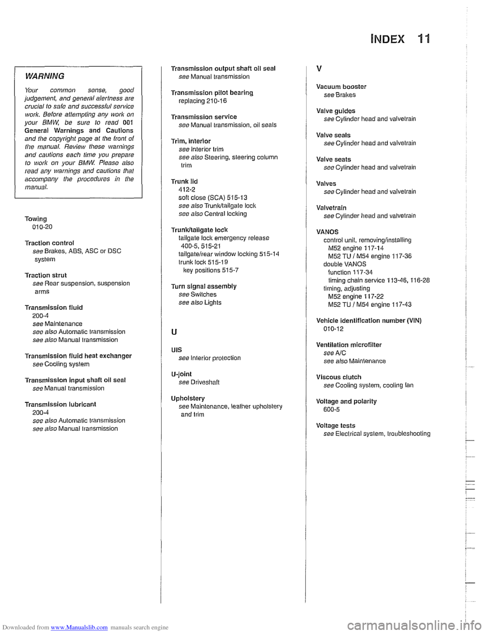
Downloaded from www.Manualslib.com manuals search engine
WARNING
Your common sense, good
judgement, and general alertness are
crucial to saie and
successiul sewice
work. Beiore attempting any work on
your BMW be sure to read 001
General Warnings and Cautions
and the copyright page
a1 the iront of
the manual. Review tliese warnings
and cautions each time you prepare
to work on your
BMW. Please also
read any warnings and
cautions that
accompany the procedures in the
manual.
Towing 010-20
Traction control
see Brakes, ABS, ASC or DSC
system
Traction strut
see Rear suspension, suspension
arms
Transmission fluid
200-4
see Maintenance
see also Automatic transmission
see also Manuai transmission
Transmission
fluid heat exchanger
see Cooling system
Transmission input shaft oil seat
see Manual transmission
Transmission lubricant
200-4 see also Automatic transmission
see also Manual
lransmission
Transmission output shafl oil seal
see Manual transmission
Transmission pilot bearing
replacing 210-16
Transmission service see Manual transmission, oil seals
Trim, interior
see interior trim
see also Steering, steering column
trim
Trunk lid
412-2 soft close (SCA) 515-13
see also Trunkltailgale loci(
see also Central iocl
tailgate loci( emergency release
400-5, 515-21 tailgatelrear window locl(ing 515-14
trunk lock 51 5-1 9
lrey positions 515-7
Turn signai assembly
see Switches
see also Lights
UIS see Interior protection
U-joint
see Driveshaft
Upholstery see Maintenance, leather upholstery
and trim Vacuum
booster
see Brakes
Valve guides
see Cylinder
head and valvetrain
Valve seals
see Cylinder head and valvetrain
Valve seats
see Cylinder head and valvetrain
Valves see Cylinder head and
vaivelrain
Valvetrain see Cylinder head and valvetrain
VANOS control unit,
removinglinstalling
M52 engine 117-14
M52 TU i M54 engine 117-36 double VANOS
function
117-34 timing chain service 113-46. 116-28
timing, adjusting
M52 engine 117-22
M52 TU l M54 engine 117-43
Vehicle identification number (VIN)
010-12
Ventilation microfilter
see
AIC
see also Maintenance
Viscous clutch see Cooling
system, cooling tan
Voitage and polarity
600-5
Voltage tests
see Electrical system, troubleshooting