sat BMW 525i 1997 E39 Workshop Manual
[x] Cancel search | Manufacturer: BMW, Model Year: 1997, Model line: 525i, Model: BMW 525i 1997 E39Pages: 1002
Page 4 of 1002
Downloaded from www.Manualslib.com manuals search engine
Selected Boolcs and Repair Information from Bentley Publishers
MINI Cooper
MINI Cooper Service Manual: 2002-2004 Bc,illc!! Pirl~lisl!~~ ISBN 0-8376-1068-0 AlexZanardi - My Swectest Victory rllex Zmmrdi itjill! Ginrz11,cn Gns~x~ri,,i ISBN (1-8376-1249-7
BMW 3 Series IE36) Scrvire Manual: 1992-1998,318ilisliC. 323is/iC, 3?5i/is/iC, 328ilisliC, M3 Be~iili.!~ Pirl?lisliers ISBN 0-8376-0326-9
BMW
5 Series Scrvicc Manual: 1997-2002 525i, 528i. 530i. 540i, Sedan, Sport Wagon Bcrrlluy P~rlilishens ISBN 0-8376-0317-X
Porsclze Tl~c Unfair Advantage hlirrk Do,~ult,re ISBN 0-8376-0073-Iilrcj; Porsche: Excellcncc Was Expected I
Porschc 911 Enthusiast's CompanionT3' Aiirinri Slr~,tzlli~~r ISBN 0-8376-0293-9
BMW 6 Scries Enthusiasl's CompanionTh1 Jc~.li'iil!/ liV0l10li ISBN 0-8376-0193-2 Driving Tlw Skip Bizl.bul- Riicing Sclaiol ISBN 0-8376-0227-0
BMW 7 Series Servicc Manual:1988-1994, 735i,735iL, 74%. 740iL. 750iL Beritlc!/ I'irblislrens ISBN 0-8376-0328-5
A French I
Bosch 1-landbook for Automotive Elcctrics and Elcchonics Rillrcr I Bwcli, GrjilrH ISBN 0-8376-1050-8
Bosch Handbook for Diesel-Engine Managcmcnt Ril1iei.t Bosdl, ClrrbH ISBN 0-8376-1051-6
Bosch Handbook for
Gasolinc-Engine Management Robcrf Bosclr, G~ribH ISBN 0-8376-1052-4
'7
Battle for lhe Bcelle I
Jells, Golf, GTI Scrvicc Manual: 1999-2005 1.8L lurbo, 1.9LTDI diesel, PD dicscl, 2.0L ga5aline. 2.81 VRG B~.!iIlcy Pt,blislicrs ISBN 0-8376-125-9
New Bcctle ServiceManual:1998-20021.8L turbo, 1.91 TDI diesel, 2.0L gasoline Bailicy P~irirlishers ISBN 0-8376-0376-5
New Bcctle 1998-2005, New Beetle Convcrtible2003-2005 Official Factory
Rcpair Manual an CD-ROM
I~olkiatgurr ~JAriicricn ISBN 9784-8376-1265-2
Boscll Fuel Injection and Enginc Management Clml-Its 0. Pmbsi, SAE ISBN 0-8376-0300-5 Clzevrolet
Corvctlc Illustralcd Encyclopedia Torn Beifurli ISBN 0-8376-0928-3
Racc Car Aerodynamics losupli Kntz ISBN 0-8376-014>8
Road &Track Illustrated Automotive
Dictionary
Joltri Dilrkl ISBN 0-8376-11143-6
Scientific Design of Exl~aust and Intake Systems I'lrililr H. S,sillr 0-8376-0309-9 Corvette Fuel
Injection &Electronic Enginc Managcment 1982-2001: Clmrlcs 0. I1rol,sl, SAE ISBN 0-8376-0861-9
I'acrat Ser\,irc hl.>nu.~l: 1998-2004.1.81. lurbu, 2.RL Vb, .l.IIL \\'8, inrludinl: tv.~gc>n and 4blOTION Giiitlc!/ P~iiblislicrs ISBN 0-8376-0360-2 Zora Arkus-Duntov:Thc Lcgcnd Behind corvt.ttc Je1.q Birl-1011 ISBN 0-8376-0858-9
Ci~evmlcl by the Numbers 1965-1969: The
Essential Chcvrolct Paris Refcrcncc illn,i Cnl2i11 ISBN 0-8376-0956-9
Passat. Passat Waron 1998-2005 Official
Gnlf,
GTI, Jctta 1993-1999, Cabrio 199% 2002 Official Factory Repair Manual on
CD-ROM
Volhsiraigu>t oJA,rtrricn ISBN 978-0-8376-1263-8
Jetta, Golf, GTI: 1993-1999,
Cabtio: 1995- 2002 Scrvicc Manual ll~iillcy I'trblisln.~~~ ISBN 0-8376-0366-8
Alfa Romco All-Alloy Twin Cam
Companion 195G1994 1'nl Bncdulr ISBN 0-8376.0275-0
Alfa Romco Owner's Bibl~'~' 1'1~1 Bmrlul! ISBN 0-8376-0707-8
Ford
Ford Fuel Injection and Electronic Engine
Control: 1988-1993
Clinrlcs 0. Pmirsl, SrlE ISBN 0-8376-03Lll-3 Arldi
Audi A4 Repair Manual: 1996-2001.1.8L lurbo, 2.8L. including Avant and quatlro Buirile!/ Ptrhlislters ISBN 0-8376-0371-.I
EuroVan Official Factory Rcp.,ir Manual:
1992-1999
I/~llhio~sar, ifAii!wicn ISBN 0-8376-0335-8
Tbc Official Ford Mustang 5.0 Technical
Reference & I'crformancc Handbook:
1979-1993
A1 l
1998-2004, Avant 1999- 2004, allroad quallro 2001-2005, 56 Avant 2002-2004, RS6 2003-2004 Official
Factory Rcpair Manual on CD-ROM
Ai!dioJ/in,er.ini ISBN 978-0-8376-1257-7
Jccp CJ Rubuildcr's Manual: 1972-1986 MOSI~S Lltii~l ISBN 0-8376-0151-7
Jccp Owner's Biblen', Third Edition Moscs Lzrdel ISBN 0-8376-1117-2 Automotive Reference
Bcnlluy Publishers has published iewicc manualsand autornohilcboolissinrc 1950. Plcasc write to us at 1734 Mniincliusctts Ave..Cnmbridge, kIA02138,i~isit ourivcb sitc, ol-c,lll 1-800-12345'15 ini a free copy ofnurcolaiog.
BMW
BMW 23 Sarvicc Manual: 1996-2002. including 23 Roadster, 23 Coupe, M
Roadster, M Coupe
Be~illq Pi,blislicis ISBN 0-8376-1250-0
BMW 3 Scrics (Ed61 Scrvicc Manual:
Mcrcedes-Bcnz Technical C~mpanion'~~' Bu,rllu!! P,rlilislio.i ISBN 11-8376-1033-8
Mcrccdcs-Bcnz E-Class (W124) O~vner's BibleT>' : 1986-1995 llu~tilc!~ Pi~lriisiieis ISBN 11-8376-0230-(1
Urlilii-!~ P~~Blisi~~rs ISBN 11-8376-11772
Page 59 of 1002
Downloaded from www.Manualslib.com manuals search engine
.-. -
Maintenance
Drive axle joint
(CV joint) boots, inspecting
CVjoint protective boots must be closely inspected forcracks
and any other damage that will allow contaminants to get into
the joint.
If the rubber boots fail, the water and dirt that enter
the joint will quickly damage it.
NOTE-
Replacement of the CVjoint boots and inspection of the
joints are described
in 331 Final Drive.
Exhaust system, inspecting
Exhaust system life varies widely according to driving habits
and environmental conditions. If short-distance driving pre-
dominates, the moisture and condensation in the system will
not fully dry out. This will lead to early corrosion damage and
more frequent replacement.
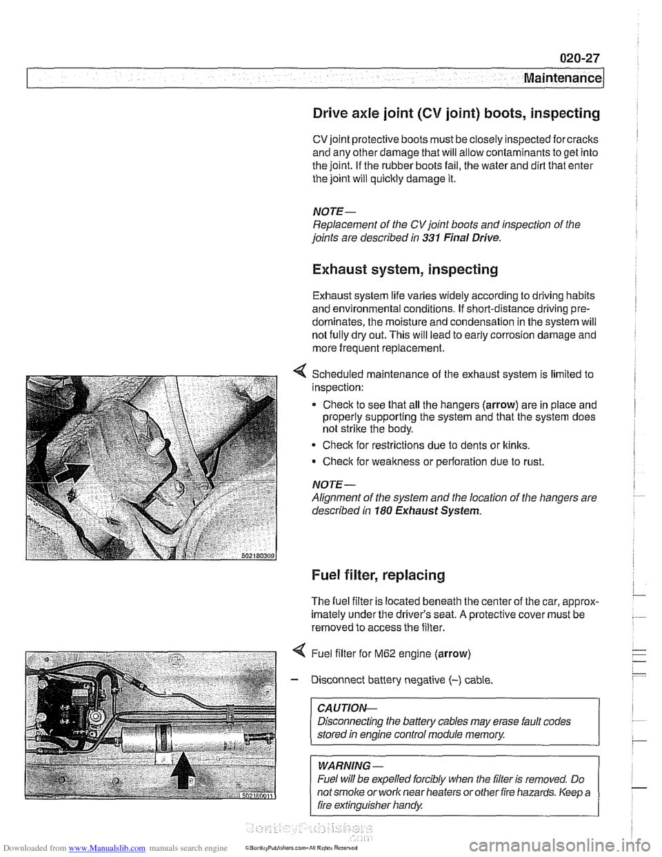
Scheduled maintenance of the exhaust system is limited to
inspection:
* Check to see that all the hangers (arrow) are in place and
properly supporting the system and that the system does
not strike the body.
Check for restrictions due to dents or
kinlts,
Check for weakness or perforation due to rust.
NOTE-
Alignment of the system and the location of the hangers are
described in
180 Exhaust System.
Fuel filter, replacing
The fuel filter is located beneath the center of the car, approx-
imately under the driver's seat.
A protective cover must be
removed to access the filter.
4 Fuel filter for M62 engine (arrow)
- Disconnect battery negative (-) cable
CAUTIOI\C
Disconnecting the battery cables may erase fault codes
stored
in engine control module memory.
WARNING -
Fuel will be expelled forcibly when the filter is removed. Do
notsmoke or work near heaters orother fire hazards. Keep a
fire extinguisher handy
Page 444 of 1002
Downloaded from www.Manualslib.com manuals search engine
130-54
I Fuel Injection ldle speed control valve,
testing and replacing
ldle speed is maintained by the ECM through the idle speed
control valve. The idle control function compensates for en-
gine load and engine operating conditions. ldle speed is
adaptive through the ECM and no adjustments can be made.
Before checking valve, confirm that throttle position sensor is
working correctly.
NOTE-
The test given below is an electrical check only. It does not
check the mechanical operation of the valve. If the valve is
sticking, hanging up or is sluggish in operation, substituting a
Inown good valve is the best way to check it.
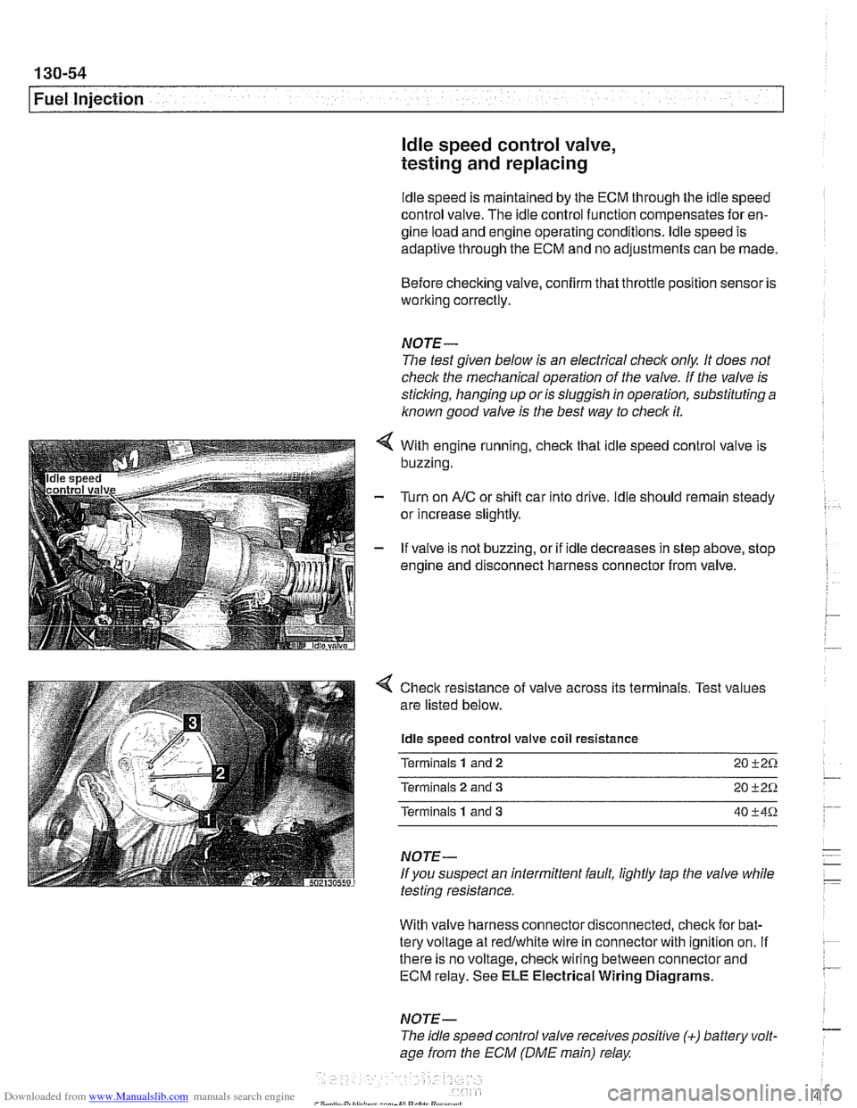
With engine running, check that idle speed control valve is
buzzing.
Turn on
AIC or shift car into drive. ldle should remain steady
or increase slightly.
If valve is not buzzing, or if idle decreases in step above, stop
engine and disconnect harness connector from valve.
4 Check resistance of valve across its terminals. Test values
are listed below.
ldle speed control valve coil resistance
Terminals
1 and 2 20 +2%
Terminals 2 and 3 20 +2Q
Terminals 1 and 3 40 +4%
NOTE-
If you suspect an intermittent fault, lightly tap the valve while
testing resistance.
With valve harness connector disconnected, check for bat-
tery voltage at redlwhite wire in connector with ignition on.
If . ~~ ~~
there is no voltage, check wiring between connector and 7 ECM relay. See ELE Electrical Wiring Diagrams.
NOTE- - The idle speed control valve receivespositive (+) battery volt-
age from the ECM (DME main) relay
Page 485 of 1002
Downloaded from www.Manualslib.com manuals search engine
.-
err- .- Fuel Tank and Fuel Pump
FUELPUMP AND FUELLEVELSENDER
E39 models use a two-lobed fuel tank. Each lobe of the tank
has its own fuel level sending unit. Each sender has a float
connected to a variable resistance wipercontact. To equalize
fuel level between the two
tank lobes, a siphon pump is in-
stalled in the left lobe.
When replacing asender or fuel pump, always replace hose
clamps,
gasltets and O-rings.
WARNING
-
When removing the fuel level sender or the fuel pump, the
fuel tank should be drained to
1/4 capacity or below as de-
scribed later in this repair group.
NOTE-
The compensating siphon pump maintains the fuel level be-
tween the right and left tank lobes. If fuel level sender resis-
tances are not approximately the same on left and right,
remove the senders and visually inspect the level in each
lobe. If the levels are different, check the siphon pump.
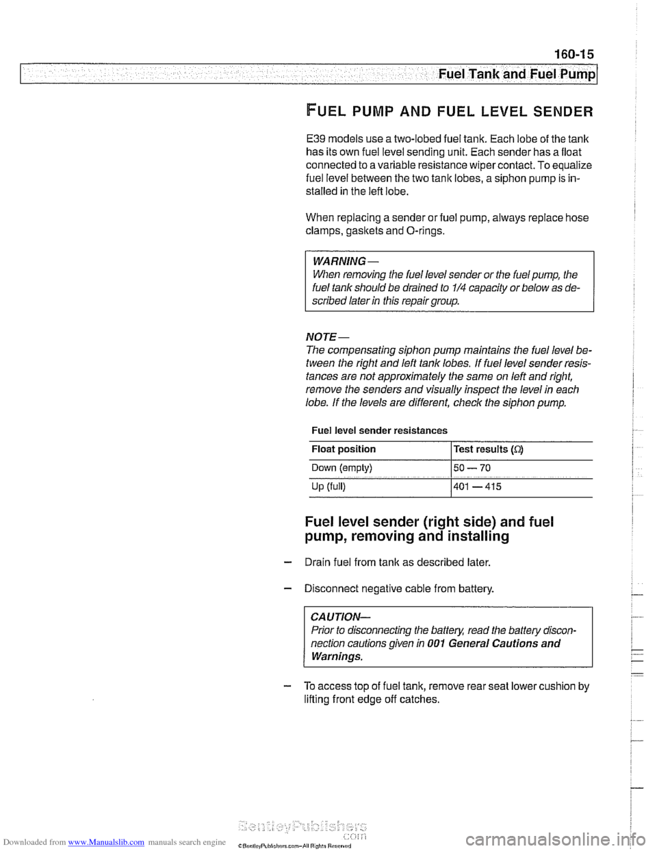
Fuel level sender resistances
Float position
l~est results (Q
Down (empty) 150- 70
Up (full) 1401 -415
Fuel level sender (right side) and fuel
pump, removing
and installing
- Drain fuel from tank as described later.
- Disconnect negative cable from battery.
CAUTION-
Prior to disconnecting the battery, read the battery discon-
nection cautions given in
001 General Cautions and
Warnings.
- To access top of fuel tank, remove rear seat lower cushion by
lifting front edge
off catches.
Page 489 of 1002
Downloaded from www.Manualslib.com manuals search engine
7 .- A Fuel Tank and Fuel Pump
Siphon pump, removing and installing
The fuel compensating siphon pump equalizes fuel level
between the two fuel tank lobes.
- Drain fuel tank as described later,
WARNING -
Fuel may be spilled. Do not smoke or work near heaters or
other fire hazards.
- Remove left and right fuel level sensors and fuel pump as
described earlier.
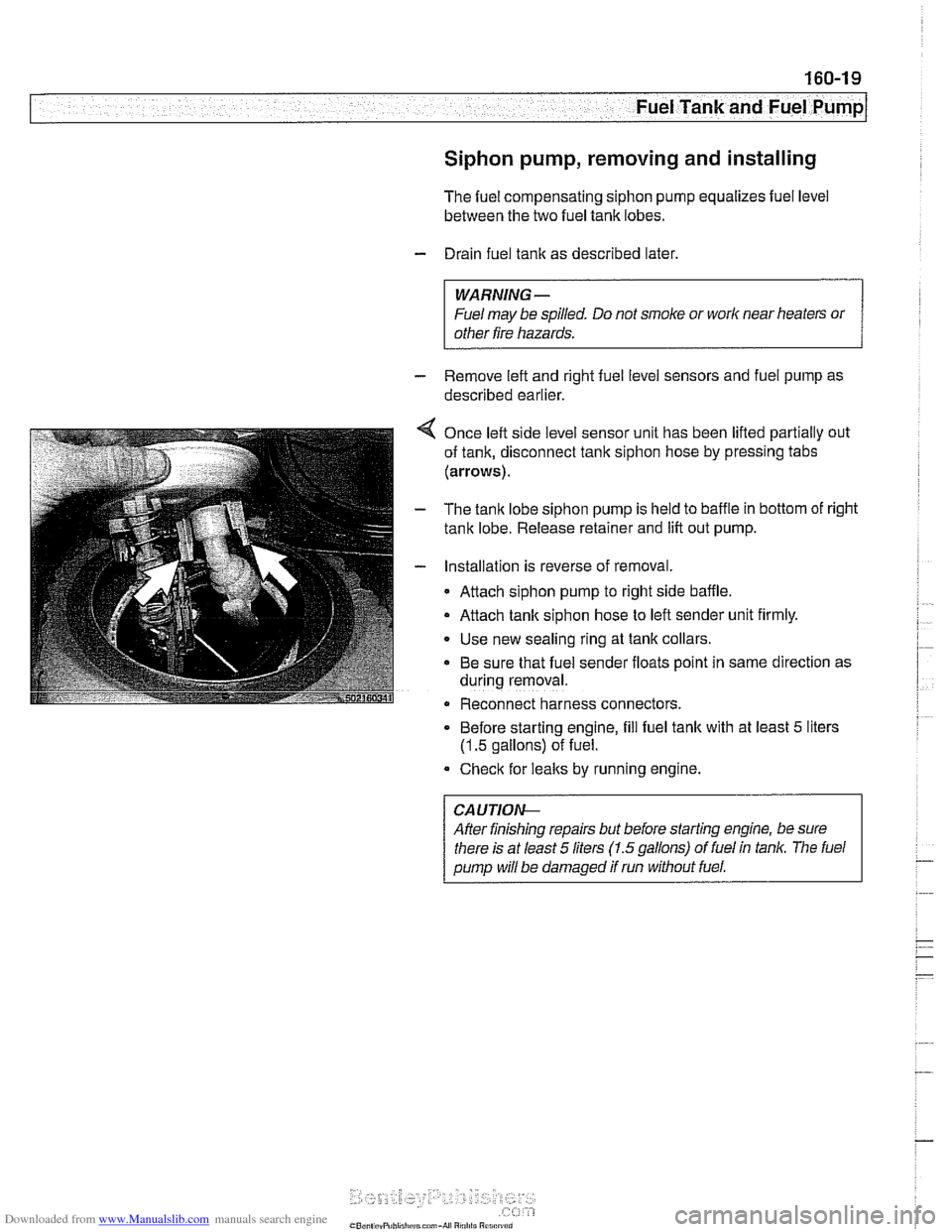
4 Once left side level sensor unit has been lifted partially out
of tank, disconnect tank siphon hose by pressing tabs
(arrows).
- The tank lobe siphon pump is held to baffle in bottom of right
tank lobe. Release retainer and lift out pump.
- Installation is reverse of removal.
Attach siphon pump to right side baffle.
Attach tank siphon hose to left sender unit firmly.
Use new sealing ring at tank collars
Be sure that fuel sender floats point in same direction as
during removal.
Reconnect harness connectors.
. Before starting engine, fill fuel tank with at least 5 liters
(1.5 gallons) of fuel.
Check for
leaks by running engine.
Afler finishing repairs but before starting engine, be sure
Page 490 of 1002
Downloaded from www.Manualslib.com manuals search engine
--
I Fuel Tank and Fuel Pump
The plastic fuel tank is mounted underneath the center of the
car (underneath the rear seat). Mounted in the fuel tank are
the fuel pump and fuel level sending units. Connecting lines
for the evaporative emission control system and expansion
tank are also attached to the tank.
Fuel
tank capacity for E39 models
Tank capacity
70 liters (18.5 gal)
Reserve capacity
8 liters (2.1 gal)
Fuel tank, draining
Drain fuel tank into a safe storage unit using an approved fuel
pumping device.
WARNING-
# Before removing tank, be sure that all hot components,
such as the exhaust system, are completely cooled down.
Fuel may be spilled. Do not smoke or
work near heat-
ers or other fire hazards.
- Start engine and allow to run 10 - 15 seconds to fill fuel com-
pensating siphon assembly. This will allow both lobes of fuel
tank to he drawn off through fuel filler pipe,
- Disconnect negative cable from battery.
CAUTION-
Prior to disconnecting the batteg read the battery discon-
nection cautions given
in 001 General Warnings and Cau-
tions.
- Remove fuel tank filler cap
- Slide suction hose into filler neck about 130 cm (51 in.), twist-
ing as necessary. Withdraw fuel into storage unit.
- Monitor fuel level reduction in both lobes:
- Remove rear seat cushion and access both fuel tank send-
er harness connectors.
Use multimeter to measure resistance at both senders,
Resistance should drop as fuel level drops.
- If siphoning mechanism is faulty, drain left tank lobe sepa-
rately by removing sender cover and pumping fuel directly
out of left lobe.
Page 525 of 1002
Downloaded from www.Manualslib.com manuals search engine
... .
Exhaust System
- With exhaust system fully cold, raise and support car for ac-
cess to exhaust system.
WARNING -
Do not worlc under a lifted car unless it is solidly supported on
jack stands designed for that purpose. Never work under a
car that is supported solely by a
jack.
- Disconnect oxygen sensor connector(s).
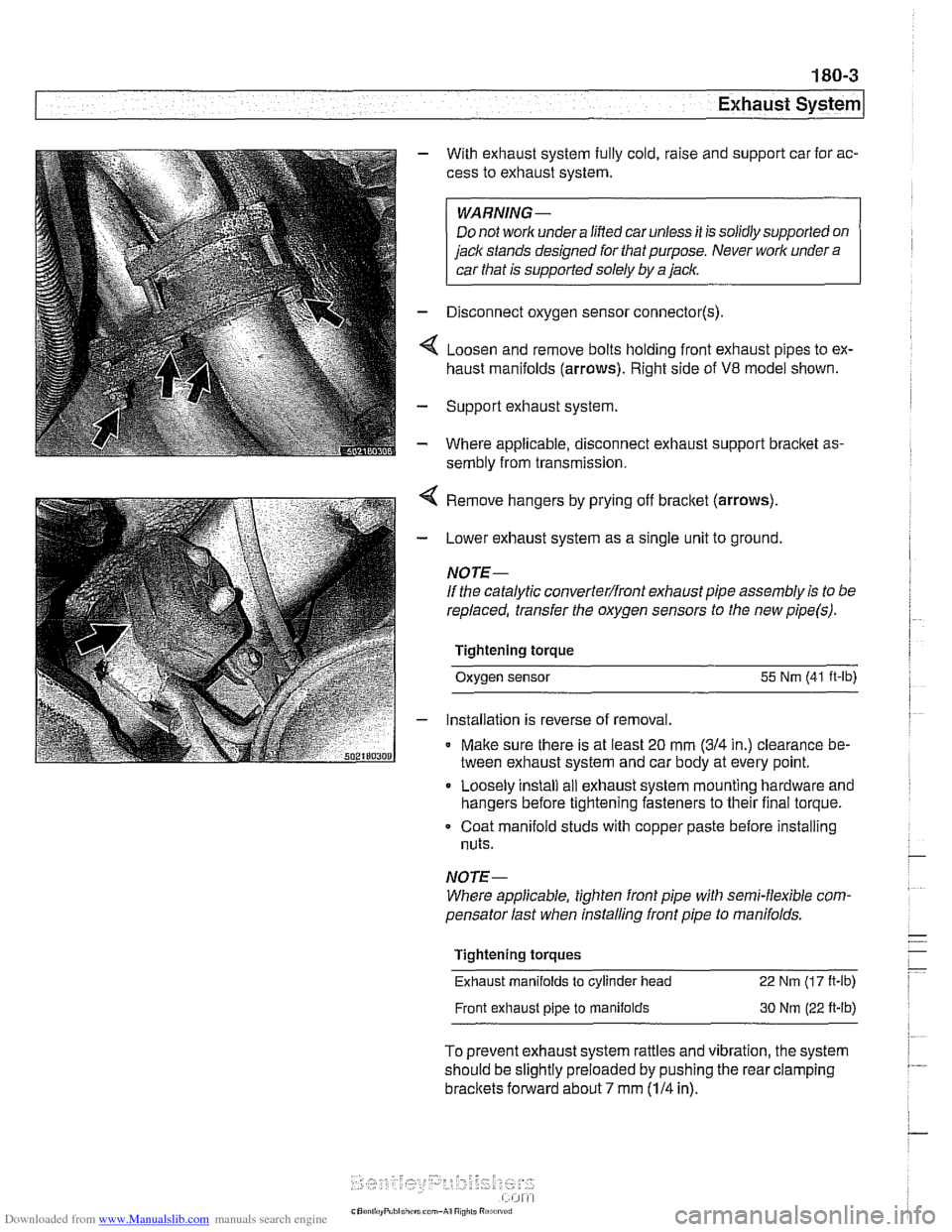
4 Loosen and remove bolts holding front exhaust pipes to ex-
haust manifolds (arrows). Right side of
V8 model shown.
- Support exhaust system
- Where applicable, disconnect exhaust support bracket as-
sembly from transmission.
< Remove hangers by prying off bracket (arrows).
- Lower exhaust system as a single unit to ground.
NOTE-
If the catalytic converterlfront exhaust pipe assembly is to be
replaced, transfer the oxygen sensors to the new
pipe(s).
Tightening torque
Oxygen sensor
55 Nm (41 ft-lb)
- installation is reverse of removal.
* Make sure there is at least 20 mm (314 in.) clearance be-
tween exhaust system and car body at every point.
Loosely install
ail exhaust system mounting hardware and
hangers before tightening fasteners to their final torque.
Coat manifold studs with copper paste before installing
nuts.
NOTE-
Where applicable, tighten front pipe with semi-flexible com-
pensator last when installing front pipe to
manifolds.
Tightening torques
Exhaust manifolds
to cylinder head 22 Nm (1 7 It-lb)
Front exhaust pipe to manifolds 30 Nm (22 ft-lb)
To prevent exhaust system rattles and vibration, the system
should be slightly preloaded by pushing the rear clamping
brackets forward about 7 mm (114 in).
Page 552 of 1002
Downloaded from www.Manualslib.com manuals search engine
21 0-1 0
Clutch
Installing the non-SAC clutch (1 997 5281 model) requires the
use of only a flywheel lock and traditional clutch disc align-
ment tool.
Installing the self-adjusting clutch (SAC) requires several
special tools for aligning and assembling the clutch, as well as
locking the flywheel in place. In addition, the procedure for re-
installing a previously used SAC differs from the procedure
for installing
a new SAC. Be sure to read the SAC installation
procedure through before starting the job.
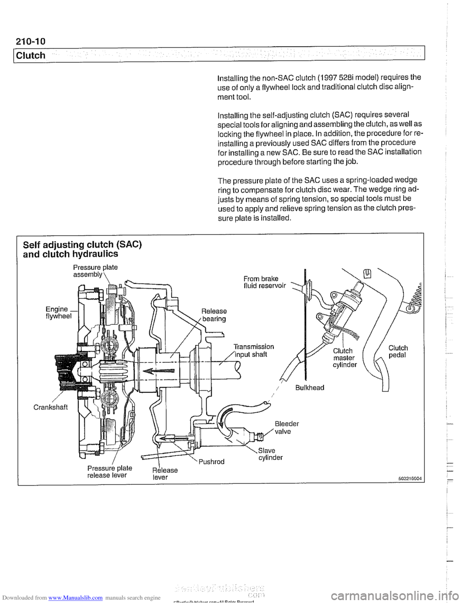
The pressure plate of the SAC uses a spring-loaded wedge
rino to cornoensate for clutch disc wear. The wedge ring
ad-
;u$s by means of spr'ng tenson, so specal toolsh~st be
used to
appy and relieve spring tension as the c utch pres-
sure plate is installed.
Self adjusting clutch (SAC)
and clutch hydraulics
Page 609 of 1002
Downloaded from www.Manualslib.com manuals search engine
Driveshaft
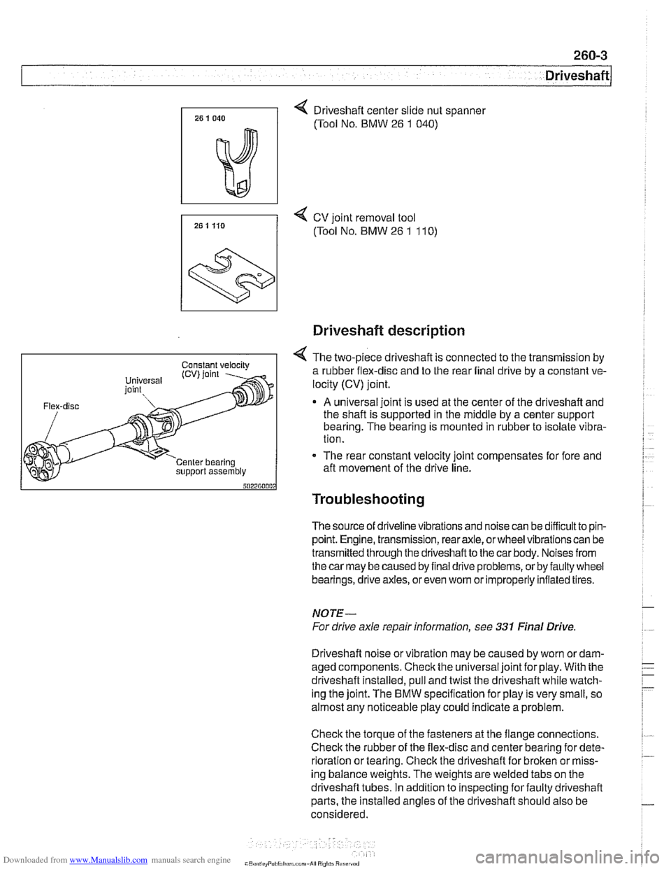
4 Driveshaft center slide nut spanner
(Tool No. BMW
26 1 040)
7, 25 1 Ho 4 cv joint removal tool
(Tool No. BMW 26 1 11 0)
support assembly
Driveshaft description
4 The two-piece driveshaft is connected to the transmission by
a rubber flex-disc and to the rear final drive by a constant ve-
locity (CV) joint.
A universal joint is used at the center of the driveshaft and
the shaft is supported in the middle by a center support
bearing. The bearing is mounted in rubber to isolate vibra-
tion.
- The rear constant velocity joint compensates for fore and
aft movement of the drive line.
Troubleshooting
The source of driveline vibrations and noise can be difficultto pin-
point. Engine, transmission, rear axle, or wheel vibrations can be
transmitted through thedriveshaftto the car body. Noises from
thecar may be caused by final drive problems, or by faulty wheel
bearings, drive axles, or even
wom or improperly inflated tires.
NOTE-
For drive axle repair information, see 331 Final Drive
Driveshaft noise or vibration may be caused by worn
ordam-
aged components. Check the universal joint for play. With the
driveshaft installed, pull and twist the driveshaft while watch-
ing the joint. The
BMW specification for play is very small, so
almost any noticeable play could indicate a problem.
Check the torque of the fasteners at the flange connections.
Check the rubber of the flex-disc and center bearing for dete-
rioration or tearing. Check the driveshaft for broken or miss-
ing balance weights. The weights are welded tabs on the
driveshaft tubes. In addition to inspecting for faulty driveshaft
parts, the installed angles of the driveshaft should also be
considered.
Page 626 of 1002
Downloaded from www.Manualslib.com manuals search engine
300-6
/Suspension, Steering and Brakes - General
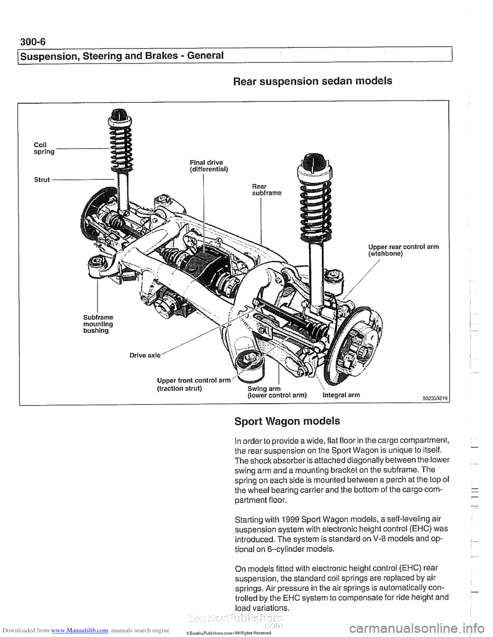
Rear suspension sedan models
Coil spring
Strut
-
'01 arm
Sport Wagon models
In order to provide a wide, ilat iloor in the cargo compartment,
the rear suspension on the Sport Wagon is unique to itself.
The shoclcabsorber is attached diagonally between the lower
swing arm and a mounting bracket on the subframe. The
spring on each side is mounted between a perch at the top
oi
the wheel bearing carrier and the bottom of the cargo com-
partment floor.
Starting with
1999 Sporl Wagon models, a self-leveling air
suspension system with electronic height control (EHC) was introduced. The system is standard on
V-8 models and op-
tional on 6-cylinder models.
On models fitted with electronic height control (EHC) rear
suspension, the standard coil springs are replaced by air
springs. Air pressure in the air springs is automatically con-
trolled by the
EHC system to compensate for ride height and
load variations.