diagram BMW 525i 1998 E39 Owner's Manual
[x] Cancel search | Manufacturer: BMW, Model Year: 1998, Model line: 525i, Model: BMW 525i 1998 E39Pages: 1002
Page 444 of 1002
Downloaded from www.Manualslib.com manuals search engine
130-54
I Fuel Injection ldle speed control valve,
testing and replacing
ldle speed is maintained by the ECM through the idle speed
control valve. The idle control function compensates for en-
gine load and engine operating conditions. ldle speed is
adaptive through the ECM and no adjustments can be made.
Before checking valve, confirm that throttle position sensor is
working correctly.
NOTE-
The test given below is an electrical check only. It does not
check the mechanical operation of the valve. If the valve is
sticking, hanging up or is sluggish in operation, substituting a
Inown good valve is the best way to check it.
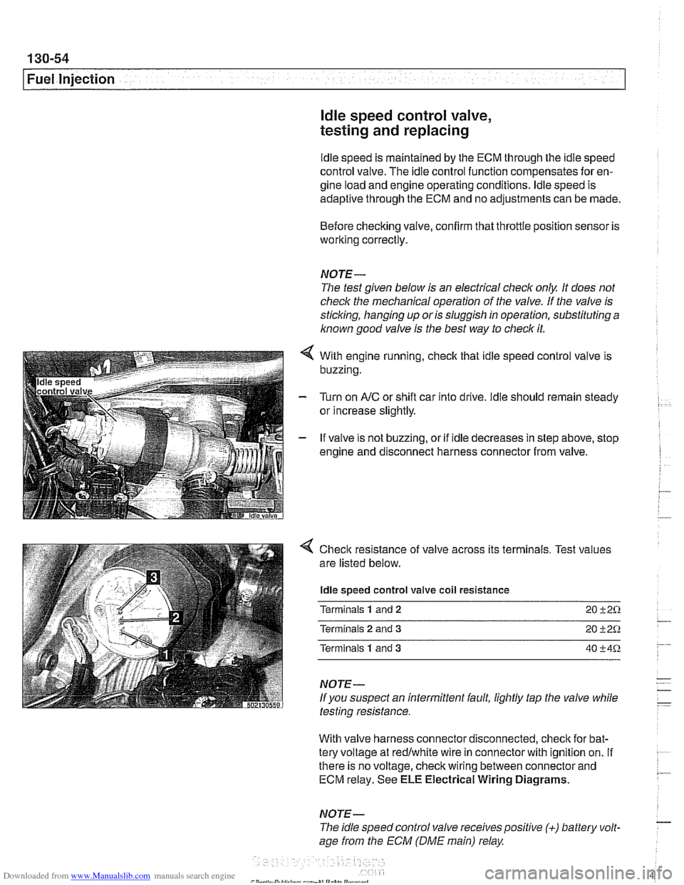
With engine running, check that idle speed control valve is
buzzing.
Turn on
AIC or shift car into drive. ldle should remain steady
or increase slightly.
If valve is not buzzing, or if idle decreases in step above, stop
engine and disconnect harness connector from valve.
4 Check resistance of valve across its terminals. Test values
are listed below.
ldle speed control valve coil resistance
Terminals
1 and 2 20 +2%
Terminals 2 and 3 20 +2Q
Terminals 1 and 3 40 +4%
NOTE-
If you suspect an intermittent fault, lightly tap the valve while
testing resistance.
With valve harness connector disconnected, check for bat-
tery voltage at redlwhite wire in connector with ignition on.
If . ~~ ~~
there is no voltage, check wiring between connector and 7 ECM relay. See ELE Electrical Wiring Diagrams.
NOTE- - The idle speed control valve receivespositive (+) battery volt-
age from the ECM (DME main) relay
Page 449 of 1002
Downloaded from www.Manualslib.com manuals search engine
130-59
Fuel Injection
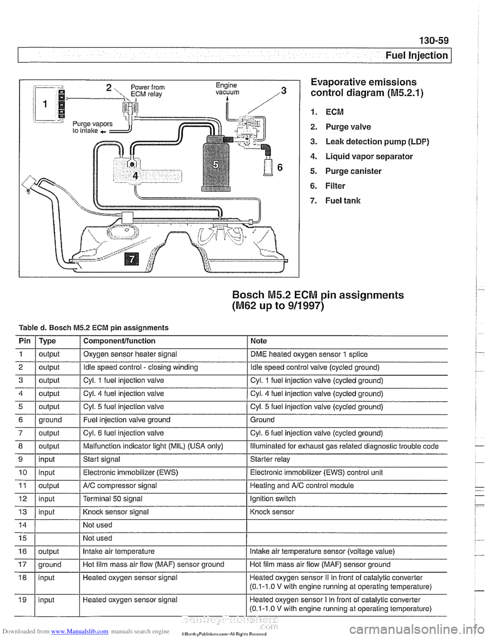
:-- -i. Evaporative emissions
1.
control diagram (M5.2.1)
i 1
i I @ 1. ECM r.=.:-:, 2. Purge valve
3. Leak detection pump (LDP)
4. Liquid vapor separator
5. Purge canister
6. Filter
Bosch M5.2 ECM pin assignments
(M62 up to 911997)
Tabled. Bosch M5.2 ECM pin assignments
I' 1- 1. . . -
4 1 output / Cyl. 4 fuel injection valve I Cyl. 4 fuel injection valve (cycled ground)
Pin
1
2
3
i I
I
7 / output I Cyl. 6 fuel injection valve I Cyl. 6 fuel injection valve (cycled ground)
Type
output
output
output
I I ,
8 1 output I Malfunction indicator light (MIL) (USA only) I lliumlnated for exhaust gas related diagnostic trouble code
5
Component/function
Oxygen sensor heater signal
Idle speed control -closing winding
Cvl. 1 fuel iniection valve Note
DME heated oxygen sensor
1 splice
idle speed control valve (cycled ground)
Cvl. 1 fuel iniection valve lcvcled around)
6 1 ground I Fuel injection valve ground 1 Ground
output
9
Not
used
Not used
11
12
13
Cyl. 5 fuel injection valve
10 1 input I Electronic immobilizer (EWS) / Electronic immobilizer (EWS) control unit
input
Heated oxygen sensor signal Cyl.
5 fuel injection
valve (cycled ground)
output
input
input
16
Start signal Starter relay
NC compressor signal
Terminal
50 signal
Knock sensor signal
17 1 ground I Hot film mass air flow (MAF) sensor ground I Hot film mass air flow (MAF) sensor ground
output Heating and
A/C control module
Ignition switch
Knock sensor
Intake air temperature intake air temperature sensor (voltage value)
Page 456 of 1002
Downloaded from www.Manualslib.com manuals search engine
Fuel Injection
When system faults are detected, a diagnostic trouble code
(DTC) is stored in the engine control module (ECM). The MIL
also illuminates
if an emissions-related fault is detected.
When faults arise, or
if the malfunction indicator lamp (MIL) is
illuminated, begin troubleshooting by connecting BMW ser-
vice tester
DISplus, MoDiC, GTl or equivalent scan tool. The
capabilities of OBD
II software has the potential to save hours
of diagnostic time and to help avoid incorrect component re-
placement and possible damage to system components.
CA UTIOI\C
The tests in this section may set fault codes (DTCs) in the
ECM and illuminate the MIL. After all testing is completed,
access and clear DTC fault memory using an OBD
I1 or
BMW compatible scan tool. See OBD On-Board Diag-
nostics.
. Only use a digital multimeter for electrical tests.
Relay positions can vary. Be sure to confirm relay posi-
tion by identifying the wiring in the
socket using the wir-
ing diagrams found in ELE Electrical Wiring
Diaqrams.
NOTE-
= OBD I1 fault memory (including an illuminated MIL) can
only be reset using the special scan tool. Removing the
connector from the ECM or disconnecting the battery will
not erase the fault memory.
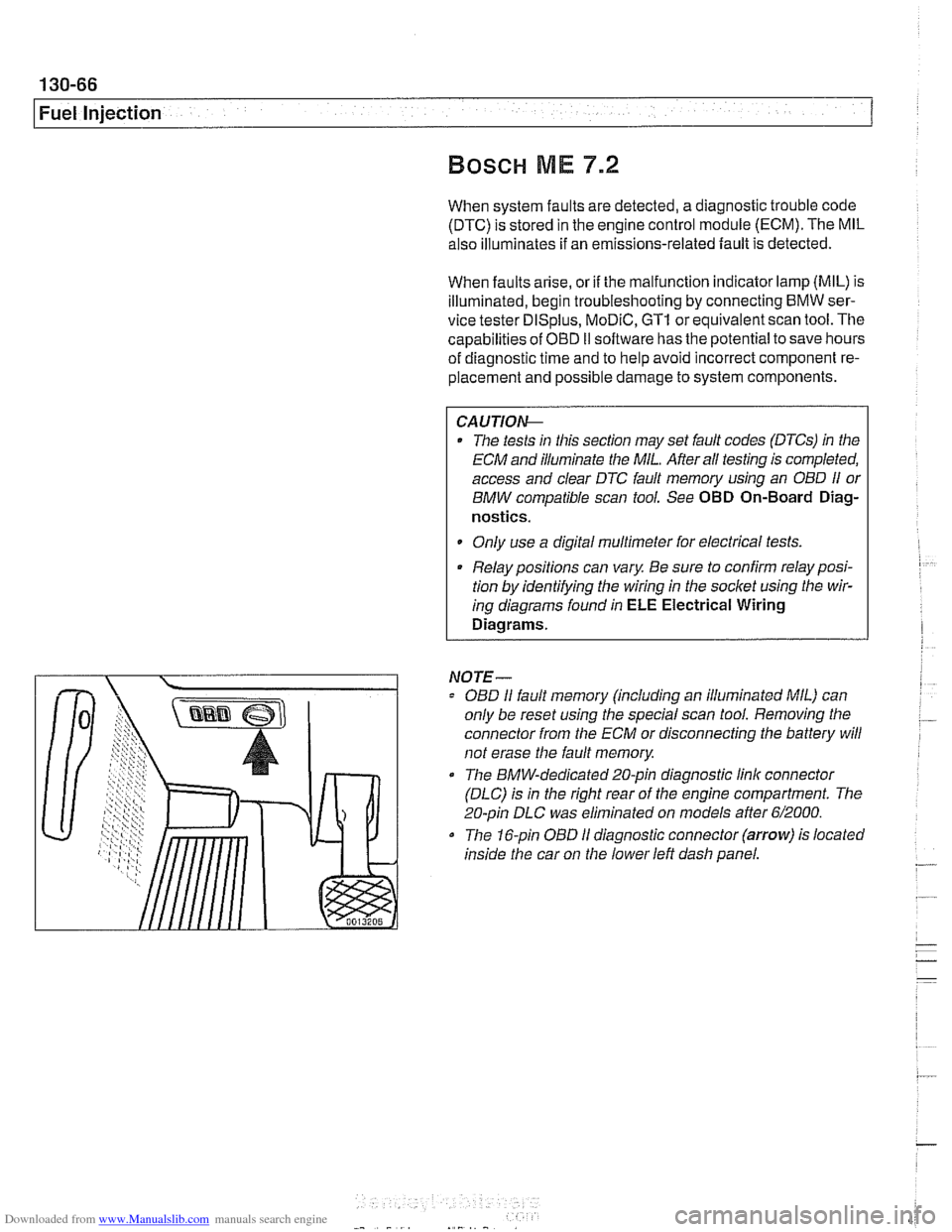
0 The BMW-dedicated 20-pin diagnostic link connector
(DLC) is in the right rear of the engine compartment. The
20-pin DLC was eliminated on models after
6/2000.
The 16-pin OBD I1 diagnostic connector (arrow) is located
inside the car on the lower left dash panel.
Page 460 of 1002
Downloaded from www.Manualslib.com manuals search engine
130-70
Fuel Injection
ECM relay
--
CAUTION-
Relay positions can vary Be sure to confirm relay position by
identifying the wiring in the
socl(et using the wiring diagrams
in ELE Electrical Wiring Diagrams.
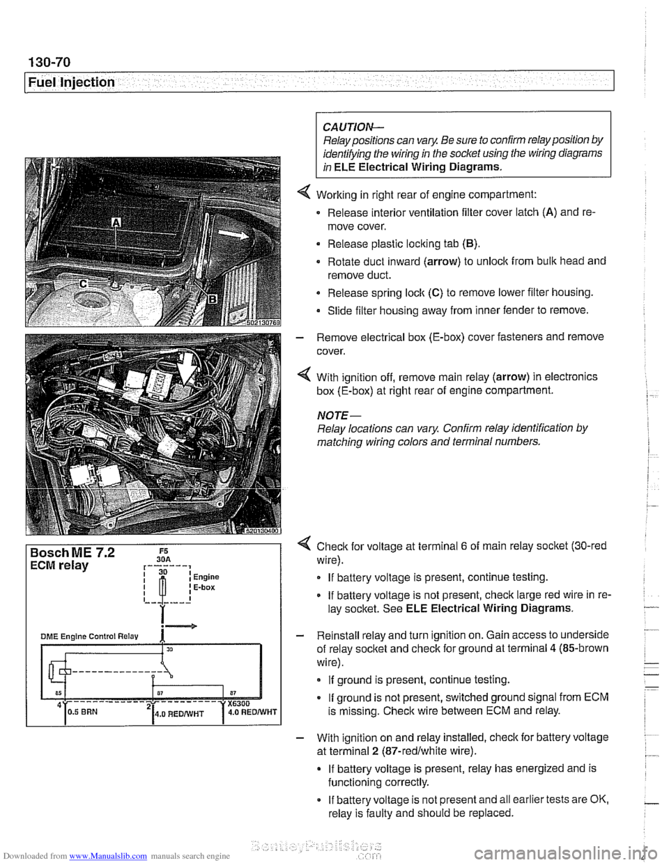
Working in right rear of engine compartment:
Release interior ventilation filter cover latch
(A) and re-
move cover.
Release plastic locking tab
(B).
Rotate duct inward (arrow) to unlock from bulk head and
remove duct.
Release spring
loclt (C) to remove lower filter housing.
Slide filter housing away from inner fender to remove.
- Remove electrical box (E-box) cover fasteners and remove
cover.
4 With ignition off, remove main relay (arrow) in electronics
box (E-box) at right rear of engine compartment.
NOTE-
Relay locations can vary Confirm relay identification by
matching wiring colors and terminal numbers.
4 Check for voltage at terminal 6 of main relay socket (30-red
wire).
If battery voltage is present, continue testing.
If battery voltage is not present, check large red wire in re-
lay socltet. See ELE Electrical Wiring Diagrams.
- Reinstall relay and turn ignition on. Gain access to underside
of relay socket and check for ground at terminal
4 (85-brown
wire).
If ground is present, continue testing.
If ground is not present, switched ground signal from ECM
is missing. Check wire between ECM and relay.
- With ignition on and relay installed, check for battery voltage
at terminal
2 (87-redlwhite wire).
If battery voltage is present, relay has energized and is
functioning correctly.
If battery voltage is not present and all earlier tests are OK.
relay is faulty and should be replaced.
Page 477 of 1002
![BMW 525i 1998 E39 Owners Manual Downloaded from www.Manualslib.com manuals search engine
- Fuel Tank and Fuel pump]
Remove fuel pump
relay (arrow).
4 Connect relay socitet terminal 6 (redlviolet wire) to relay
socket termi BMW 525i 1998 E39 Owners Manual Downloaded from www.Manualslib.com manuals search engine
- Fuel Tank and Fuel pump]
Remove fuel pump
relay (arrow).
4 Connect relay socitet terminal 6 (redlviolet wire) to relay
socket termi](/img/1/2822/w960_2822-476.png)
Downloaded from www.Manualslib.com manuals search engine
- Fuel Tank and Fuel pump]
Remove fuel pump
relay (arrow).
4 Connect relay socitet terminal 6 (redlviolet wire) to relay
socket terminal
2 (whitelblue wire) with a fused jumper wire.
After completing tests, remove jumper harness.
CA
UTIOG
Relay locations may vary Use care when identifying relays
and making electrical checks at
the fuse/relay panel. See
610 Electrical Component Locations for additional re-
lay information.
The fuel pump relay has a 1.5
md red/violet wire at
terminal
6 in the relay socket. Terminal2 has a 2.5md
white/blue wire. See ELE Electrical Wiring Diagrams
for additional wiring information.
NOTE-
* The fuel pump will run as soon as the jumper wire Is at-
tached.
The jumper wire should be 1.5
md (14 ga.) and include
an in-line fuse holder with a 15A fuse. To avoid
fuse/relay
panel damage from repeated connecting and disconnect-
ing, also include a toggle switch in the jumper harness.
- If pump does not run with jumper installed, fault could be in
fuel pump, fuses
F31 or F22 1 F54, or wiring to pump. Check
pump, fuses and its wiring as described below.
Fuel pump electrical circuit, testing
- The test given below assumes that the fuel pump relay circuit
is functioning correctly as described earlier. Access to the
pump is from below the rear seat bottom cushion.
- Remove rear seat lower cushion by lifting front edge off left
and right catches.
Page 523 of 1002
Downloaded from www.Manualslib.com manuals search engine
180 Exhaust System
General Exhaust System
. . . . . . . . . . . . . . . . .
Exhaust system, removing and installing
Muffler, replacing..
. . . . . . . . . . . . . . . . .
Exhaust Manifolds . . . . . . . . . . . . . . .
Exhaust manifolds, removing
and installing (M52 engine)
. . . . . . . . . .
Exhaust manifolds, removing and
installing (M52
TU and M54 engines) . . .
Exhaust manifolds, removing
and installing (M62 engine)
. . . . . . . . . .
Oxygen Sensors. . . . . . . . . . . . . . . . . . . . 180-9
Oxygen sensors (precatalyst),
replacing
(M52 TU and M54) . . . . . . . . . . . . 180-9
Oxygen sensors (post-catalyst),
replacing (M52
TU and M54) . . . . . . . . . . . . 180-9
Oxygen sensor, replacing
(M52 and M62 engine) . . . . . . . . . . . . . . . 180-10
Exhaust System Diagrams . . . . . . . . . 180-1 1
M52 engine (528i 1997-1 998) . . . . . . . . . . 180-1 1
M52
TU and M54 engines
(528i 1999-2000 and 5251 2001-2003) . . . 180-1 2
M54 engine
(530i 2001-2003) . . . . . . . . . . 180-1 3
M62 engine
(540i 1997-1 998) . . . . . . . . . . 180-1 4
M62
TU engine (540i 1999-2003 . . . . . . . 180-1 5
Page 621 of 1002
Downloaded from www.Manualslib.com manuals search engine
300 Suspension. Steering and Brakes .
Genera8
General ........................... .30 0.2
Aluminum suspension components
...... .30 0.2
Front Suspension ................. .30 0.2
Front suspension 6-cylinder models
(525i.5281. 530i) ..................... .30 0.3
Front suspension V-8 models (540i) ...... .30 0.4
Rear Suspension .................. .30 0.5
Sedan models
....................... .30 0.5
Rear suspension sedan models ........ .30 0.6
Sport Wagon models ................. .30 0.6
Rear suspension Sport Wagon
(with coil springs)
.................... .30 0.7
Rear suspension Sport Wagon
(EHC with air springs)
................. .30 0.8
EHC operational diagram .............. .30 0.9
Steering ......................... .30 0.10
Rack-and-pinion steering ............. .30 0.10
Recirculating ball and nut steering ...... .30 0.10
..................... Brake System 300-10
Wheels and Tires ................. 300-1 1
............... Rim and tire sizes table 300-1 1
Electronic Brake and Stability
.................. Control Systems 300-1 1
E39 electronic brake and stability
........ control systems application table 300-12
........................ ABS system 300-1 2
Automatic Stability Control (ASC)
....... 300-12
ABSIASC traction control system ....... 300-13
Dynamic Stability Control (DSC)
........ 300-14
Ride Height ....................... 300-14
......... Front ride height specifications 300-1 5
......... Rear ride height specifications 300-16
Page 629 of 1002
Downloaded from www.Manualslib.com manuals search engine
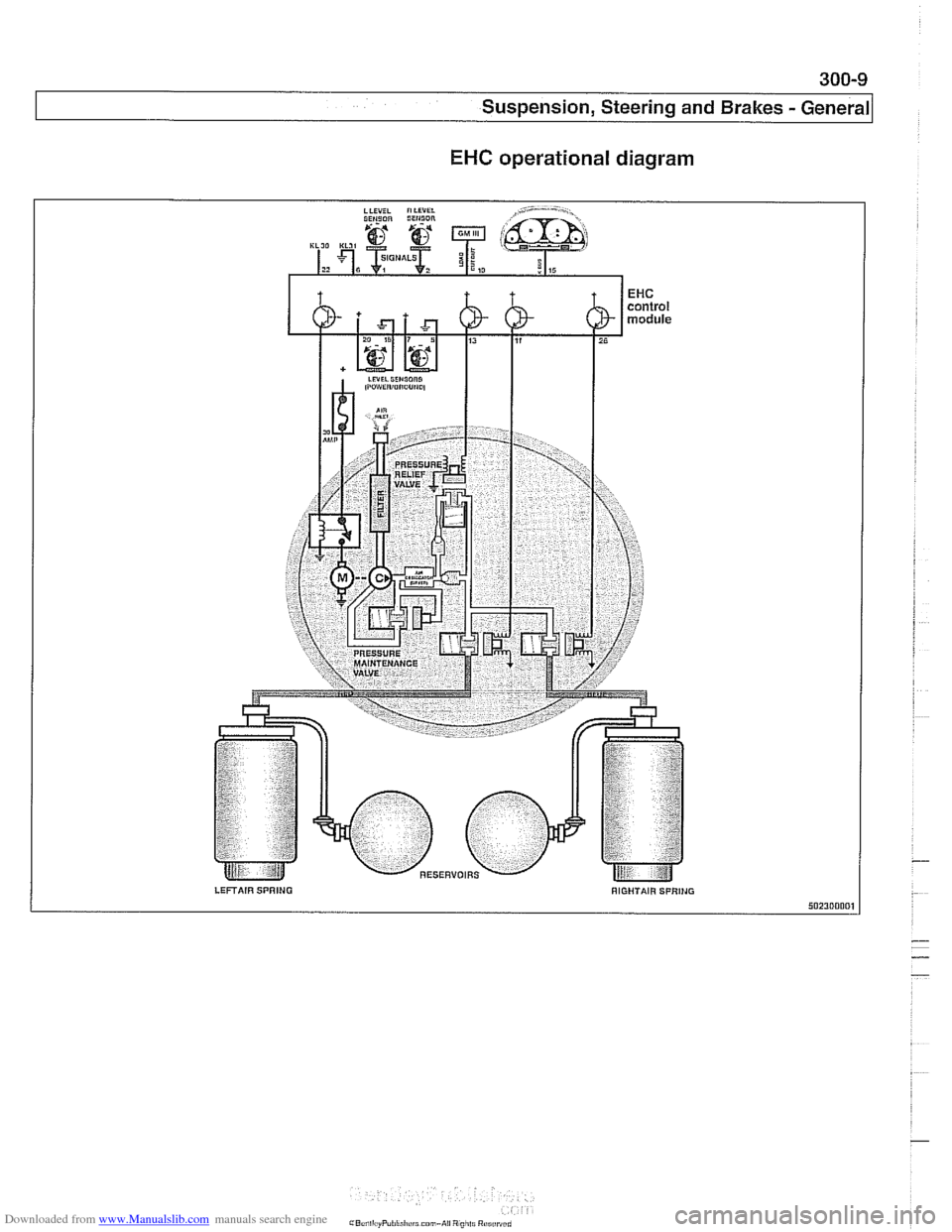
EHC operational diagram
LEFTAIR SPRING RIGHTAIR SPRlNG 50230000,
-
-
-
Page 645 of 1002
Downloaded from www.Manualslib.com manuals search engine
31 0-9
Front Suspension
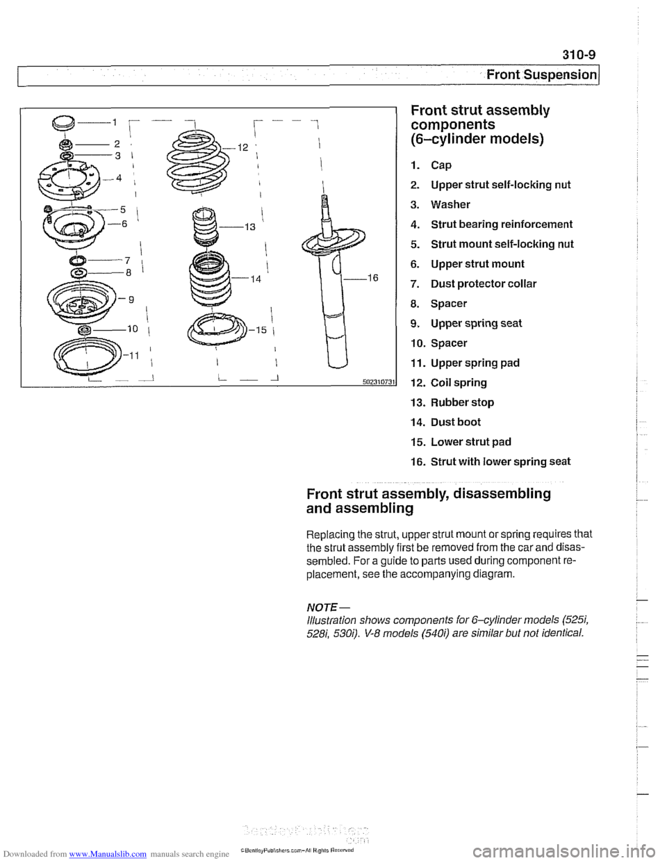
Front strut assembly
components
(6-cylinder models)
1. Cap
2. Upper strut self-locking nut
3. Washer
4. Strut bearing reinforcement
5. Strut mount self-locking nut
6. Upper strut mount
7. Dust protector collar
8. Spacer
9. Upper spring seat
10. Spacer
11. Upper spring pad
12. Coil spring
13. Rubber stop
14. Dust boot
15. Lower strut pad
16. Strut with lower spring seat
Front strut assembly, disassembling
and assembling
Replacing the strut, upper strut mount or spring requires that
the strut assembly first be removed from the car
and disas-
sembled. For a guide to parts used during component re-
placement, see the accompanying diagram.
NOTE-
Illustration shows components ior 6-cylinder models (525i,
528i, 530;). V-8 models (540i) are similar but not identical.
Page 829 of 1002
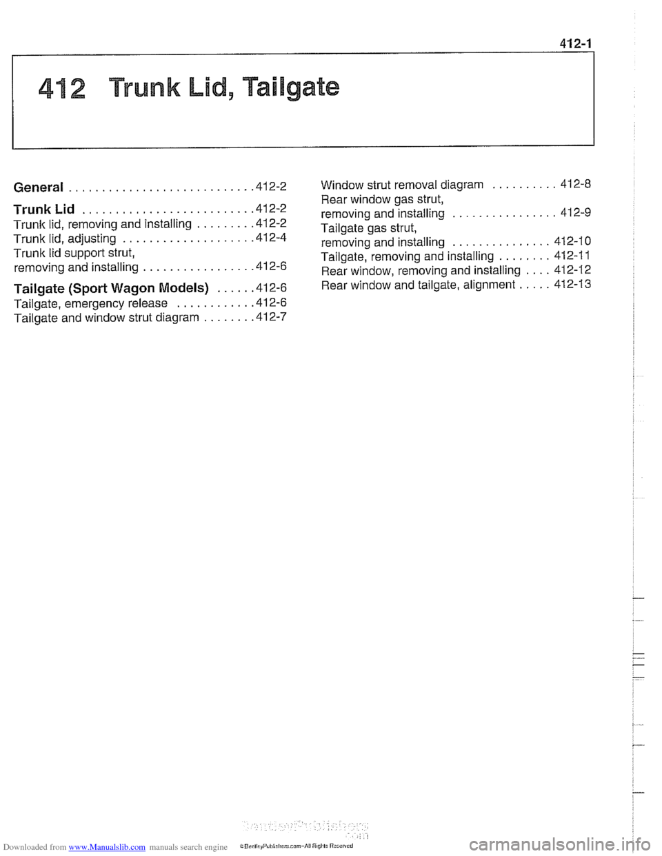
Downloaded from www.Manualslib.com manuals search engine
41 2 Trunk Lid. Tailgate
........................... General
......................... Trunk Lid
Trunlc lid. removing and installing ........
Trunk lid. adjusting ...................
Trunk lid support strut.
removing and installing
................
Tailgate (Sport Wagon Models) .....
Tailgate. emergency release ...........
Tailgate and window strut diagram .......
Window strut removal diagram .......... 412-8
Rear window gas strut.
removing and installing
................ 412-9
Tailgate gas strut. removing and installing
............... 412-10
Tailgate. removing and installing
........ 412-1 1
Rear window. removing and installing
.... 412-12
Rear window and tailgate. alignment
..... 412-13