diagnostic BMW 525i 1998 E39 Repair Manual
[x] Cancel search | Manufacturer: BMW, Model Year: 1998, Model line: 525i, Model: BMW 525i 1998 E39Pages: 1002
Page 743 of 1002
Downloaded from www.Manualslib.com manuals search engine
330-47
Rear suspension/
Ride height sensor, removing and installing
Hall effect sensors for vehicle height detection are mounted
on the
left and right sides of the rear suspension. A coupling
rod mounted between the rear suspension arm and the sen-
sor arm is used to send a varying voltage signal to the
EHC
control module.
Raise car and support safely.
WARNING-
Male sure the car is firmly supported on jaclc stands de-
signed
for the purpose. Place jaclc stands underneath struc-
tural chassis points. Do not place jaclc stands under
sus~ension Darts.
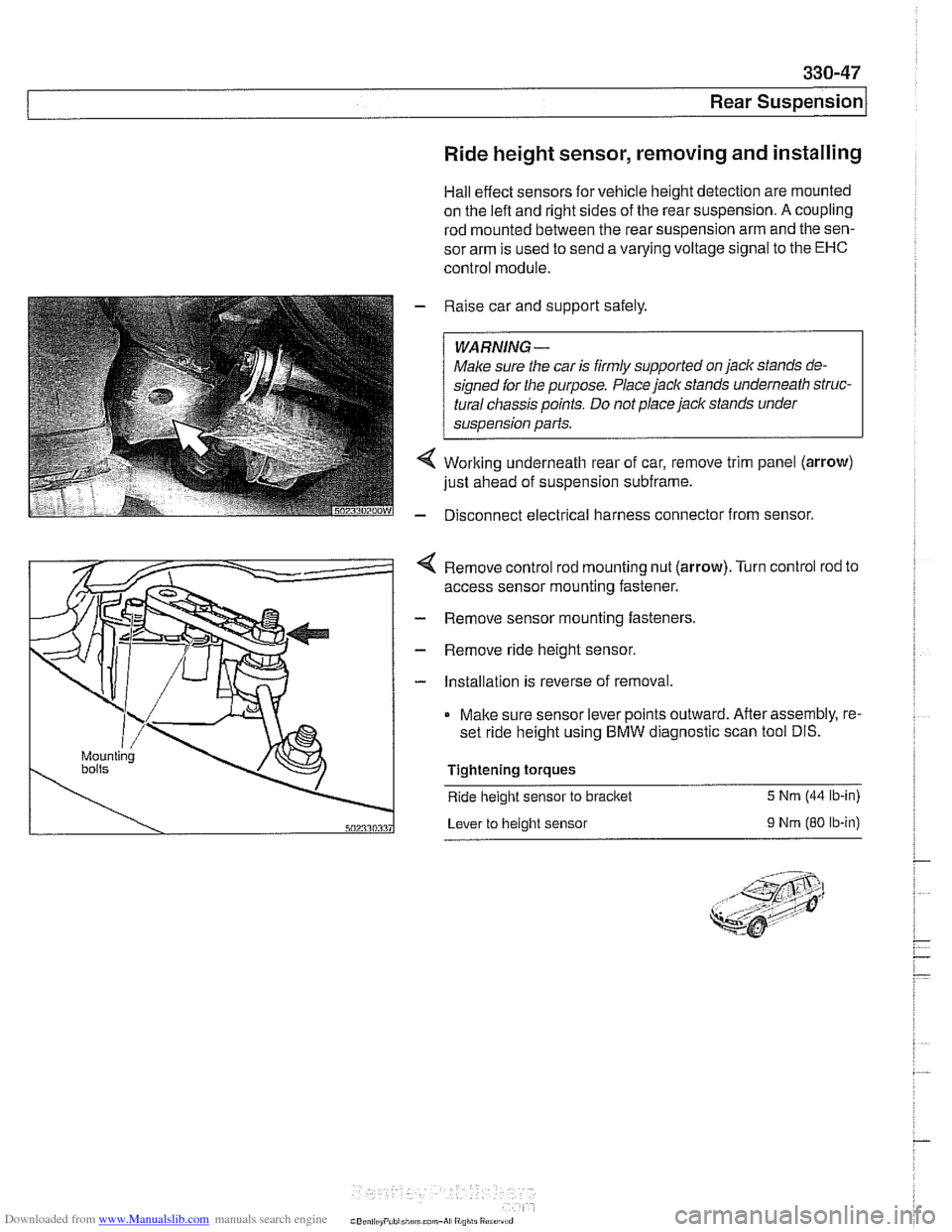
Working underneath rear of car, remove trim panel (arrow)
just ahead of suspension subframe.
Disconnect electrical harness connector from sensor.
4 Remove control rod mounting nut (arrow).Turn control rod to
access sensor mounting fastener.
- Remove sensor mounting fasteners.
- Remove ride height sensor.
- Installation is reverse of removal.
Make sure sensor lever points outward. After assembly, re-
set ride height using BMW diagnostic scan tool DIS.
Tightening torques
Ride
height sensor to bracket 5 Nrn (44 lb-in)
Lever to height sensor
9 Nrn (80 ib-in)
Page 768 of 1002
Downloaded from www.Manualslib.com manuals search engine
340-6
1 Brakes
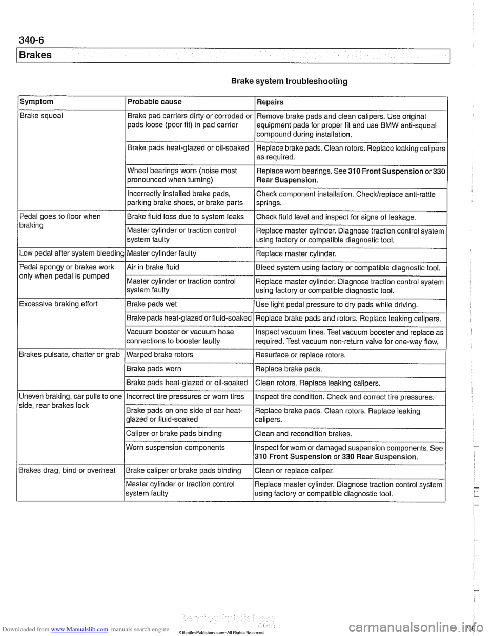
Brake system troubleshooting
/symptom I Probable cause 1 Repairs
Brake squeal
Pedal goes to floor when
bralting
Low pedal after system bleeding
Pedal spongy or brakes work
only when pedal is pumped
Excessive braking effort
Brakes pulsate, chatter or grab
Uneven
bralting, car pulls to one
side, rear braltes
loclt
Brakes drag, bind or overheat Brake
pad carriers dirty or corroded or
pads loose (poor fit) in pad carrier
Braite pads heat-glazed or oil-soaked
Wheel bearings worn (noise most
pronounced when turning)
Incorrectly Installed brake pads,
parking bralte shoes, or bralte parts
Brake fluid loss due to system leaks
Master cylinder or traction control
system faulty
Master cylinder faulty
Air in braite fluid
Master cylinder or traction control
system faulty
Brake pads wet
Brake pads
heat-glazedorfluid-soalted
Vacuum booster or vacuum hose
connections to booster faulty
--- Warped brake rotors
Brake pads worn
Brake pads heat-glazed or oil-soaked Remove
brake pads and clean calipers. Use original
equipment pads for proper fit and use BMW anti-squeal
compound during installation,
Replace brake pads. Ciean rotors. Replace leaking caliper:
as required.
Replace worn bearings. See 310 Front Suspension
or33C
Rear Suspension.
Check component installation. Checldreplace anti-rattle
springs.
Checlt fluid level and inspect for signs of leakage.
Replace master cylinder. Diagnose traction control system
using factory or compatible diagnostic tool.
Replace master cylinder.
Bleed system using factory or compatible diagnostic tool.
Replace master cylinder. Diagnose traction control system
using factory or compatible diagnostic tool.
Use light pedal pressure to dry pads while driving.
Replace
bralte pads and rotors. Replace leaking calipers.
lnspect vacuum lines. Test vacuum booster and replace as
required. Test vacuum non-return valve for one-way flow.
Resurface or replace rotors.
Replace brake pads.
Clean rotors. Replace leaiting calipers.
Incorrect tire pressures or worn tires
Brake pads on one side of car heat-
glazed or fluid-soaked
Caliper or brake pads binding
Worn suspension components
Brake caliper or brake pads binding
Master cylinder or traction control
system faulty lnspect
tire condition. Checlt and correct tire pressures.
Replace brake pads. Clean rotors. Replace leaking
calipers.
Clean and recondition brakes.
Inspect for worn or damaged suspension components. See
310 Front Suspension or 330 Rear Suspension.
Ciean or replace caliper.
Replace master cylinder. Diagnose traction control system
using faclory or compatible diagnostic tool.
Page 793 of 1002
Downloaded from www.Manualslib.com manuals search engine
340-31
Brakes
ABS 1 traction electronic control module
(1 997 -1 998 models)
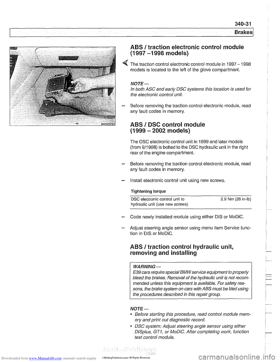
4 The traction control electronic control module in 1997- 1998
models is located to the left of the glove compartment.
NOTE-
In both ASC and early DSC systems this location is used for
the electronic control unit.
- Before removing the traction control electronic module, read
any fault codes in memory.
ABS I DSC control module
(1 999 - 2002 models)
The DSC electronic control unit in 1999 and later models
(from 911998) is bolted to the DSC hydraulic unit in the right
rear of the engine compartment.
- Before removing the traction control electronic module, read
any fault codes in memory.
- Install electronic control unit using new screws.
Tightening torque
DSC electronic control unit to 2.9 Nrn (26 in-lb)
hydraulic
unit (use new screws)
- Code newly installed module using either DIS or MoDiC.
- Adjust steering angle sensor using menu item Service func-
tion in
DIS or MoDiC.
ABS I traction control hydraulic unit,
removing and installing
WARNING -
E39 cars require special BMWsewice equipment to properly
bleed the brakes. Removal of the hydraulic unit is not recom-
mended unless this equipment is available. For safety rea-
sons, the
brake system on cars with ABS must be bled using
the procedures described in this repair group.
NOTE-
Before starting this procedure, read control module mem-
ory and print
out diagnostic record.
DSC system: Adjust steering angle sensor using
either
DISplus, GTI, or MoDiC. After completing work, function
test control module.
Page 896 of 1002
Downloaded from www.Manualslib.com manuals search engine
51 5-2
/Central Locking and Anti-Theft
This section covers repair information for door, trunk and car-
go compartment locks, central locking, electronic
immob~liza-
tion (EWS) and anti-theft alarm (DWA).
€39 cars are equipped with sophisticated self-diagnostic elec-
trical systems. When experiencing malfunctions relating to
central locking. EWS or anti-theft systems, start the diagnosis
process using the
BMW service tester DIS, GT 1, MoDiC or
equivalent scan tool. An advanced diagnostic scan tool can
usually pinpoint electrical faults quickly and safely.
Additional electrical information can be found in:
610 Electrical Component Locations
ELE Electrical Wiring Diagrams
Central locking in E39 vehicles controls the door
locks, trunk
or tailgate lock and fuel filler flap lock. The control module for
the Central Body Electronics system (ZKE
Ill), lknown as the
General Module (GM
Ill), controls central locking.
ZKE
Ill manages the following central locking related func-
tions:
Central locking
* Keyless entry
Key memory
Power trunk release
Electric opening of tailgate
DWA alarm system
Diagnosis
General Module
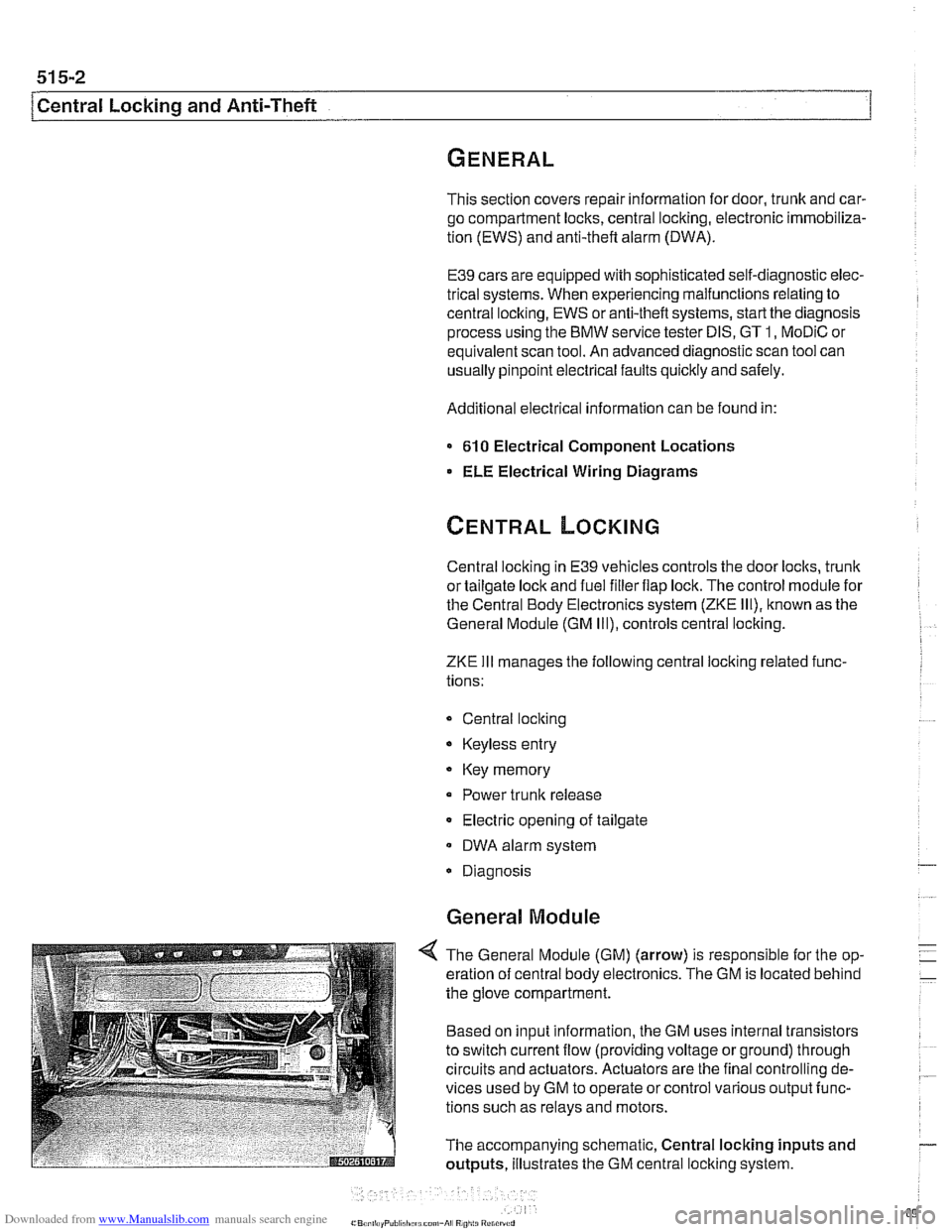
4 The General Module (GM) (arrow) is responsible for the op-
eration of central body electronics. The GM is located behind
the glove compartment.
Based on input information, the GM uses internal transistors
to switch current flow (providing voltage or ground) through
circuits and actuators. Actuators are the final controlling de-
vices used by GM to operate or control various output func-
tions such as relays and motors.
The accompanying schematic, Central locking inputs and
outputs, illustrates the GM central locking system.
Page 950 of 1002
Downloaded from www.Manualslib.com manuals search engine
721 -2
l~irba~ System (SRS)
This repair group covers airbag components and replace-
ment.
Airbag system repairand fault diagnosis is not covered.
Diagnostics, component testing, and
airbag system repair
should be carried out by trained BMW service technicians.
Individual
airbag system components can only be tested elec-
tronically when installed in the car. BMW service testers
DIS
or MoDiC or equivalent must be used for diagnostic work.
WARNING-
Special test equipment is required to retrieve airbag fault
codes, diagnose system faults, and
reseffturn off the air-
bag indicator light. The indicator light will remain on until
any problem has been corrected and the fault memory has
been cleared.
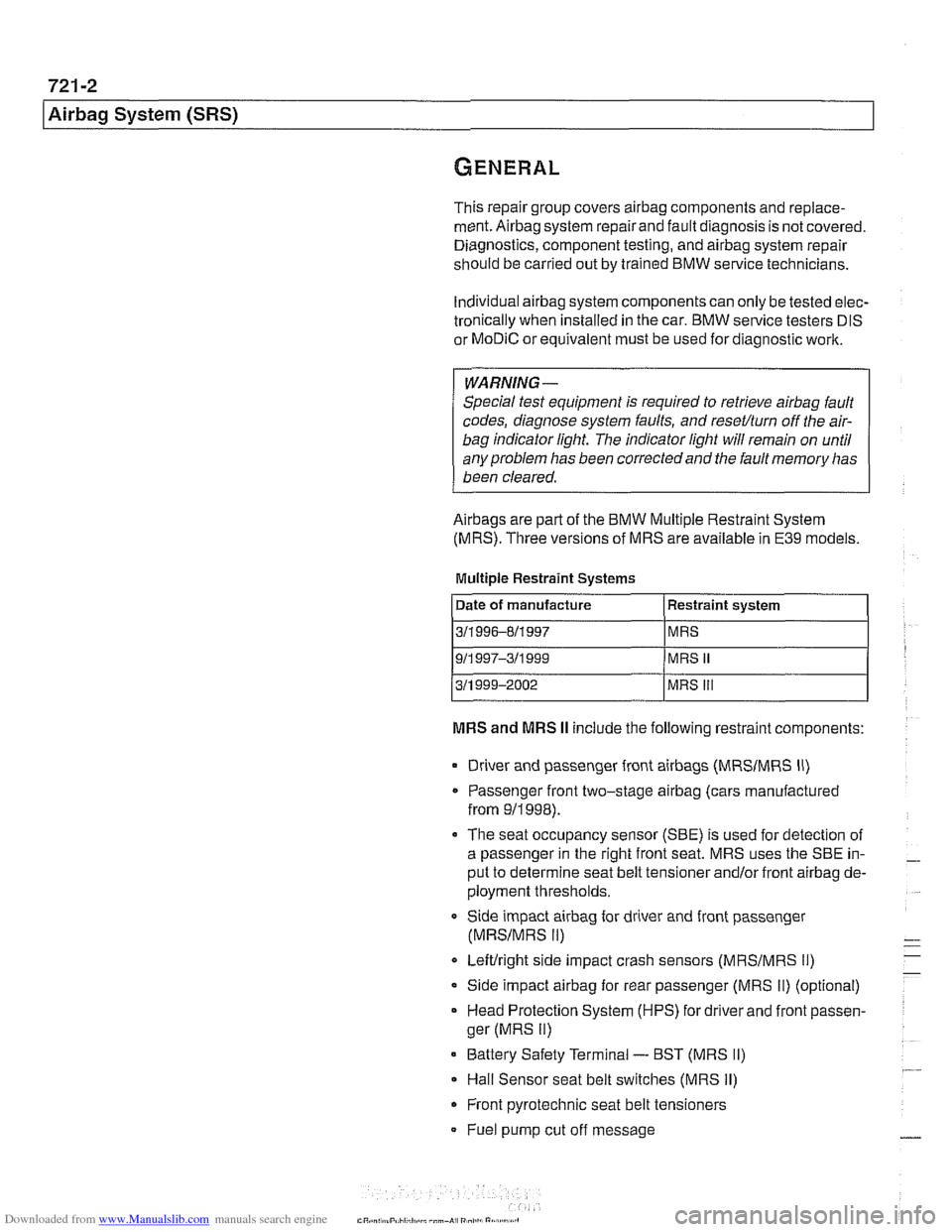
Airbags are part of the BMW Multiple Restraint System
(MRS). Three versions of MRS are available in E39 models.
Multiple Restraint Systems
MRS and MRS II include the following restraint components:
311 996-811 997
911
997-311 999
311 999-2002
Driver and passenger front
airbags (MRSIMRS II)
MRS
MRS
II
MRS Ill
Passenger front two-stage airbag (cars manufactured
from
911998).
The seat occupancy sensor (SBE) is used for detection of
a passenger in the right front seat. MRS uses the SBE in-
put to determine seat belt tensioner
and/or front airbag de-
ployment thresholds.
Side impact
airbag for driver and front passenger
(MRSIMRS II)
Leftlright side impact crash sensors (MRSIMRS 11)
Side impact airbag for rear passenger (MRS II) (optional)
Head Protection System (HPS) for driver and front passen-
ger (MRS
II)
Battery Safety Terminal - BST (MRS II)
Hall Sensor seat belt switches (MRS II)
Front pyrotechnic seat belt tensioners
Fuel pump cut off message
Page 961 of 1002
Downloaded from www.Manualslib.com manuals search engine
OBD On-Board Diagnostics
I I
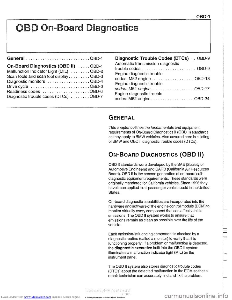
General ........................... OBD-1 Diaqnostic Trouble Codes (DTCs) . . OBD-9
On-Board Diagnostics (OBD I!) ..... OBD-I
Malfunction Indicator Light (MIL)
........ OBD-2
Scan tools and scan tool display.
........ OBD-3
Diagnostic monitors
.................. OED-4
Drive cycle
......................... OED-6
Readiness codes
.................... OBD-6
Diagnostic trouble codes
(DTCs) ........ OBD-7
-
Automatic transmission diagnostic
trouble codes
....................... OBD-9
Engine diagnostic trouble
codes: M52 engine.
................. OED-13
Engine diagnostic trouble
codes: M54 engine.
................. OBD-17
Engine diagnostic trouble
codes: M62 engine.
................. OBD-24
This chapter outlines the fundamentals and equipment
requirements of On-Board Diagnostics
I1 (OBD 11) standards
as they apply to BMW vehicles. Also covered here is a listing
of BMW and OBD
I1 diagnostic trouble codes (DTCs).
ON-BOARD DIAGNOSTICS (QBD !I)
OBD II standards were developed by the SAE (Society of
Automotive Engineers) and CARB (California Air Resources
Board).
OED I1 is the second generation of on-board self-
diagnostic equipment requirements. These standards were
originally mandated for California vehicles. Since
1996 they
have been applied
toall passengervehicles sold in the United
States.
On-board diagnostic capabilities are incorporated into the
hardware and soflwareof the enginecontrol module
(ECM) to
monitor virtually every component that can affect vehicle
emissions. The
OED I1 system works to ensure that
emissions remain as clean as possible over the life of the
vehicle.
Each emission-influencing component is checked by a
diagnostic routine (called a monitor) to verify that it is
functioning properly.
If a problem or malfunction is detected,
the
diagnostic executive built into the OBD I1 system
illuminates a malfunction indicator light (MIL) on the
instrument panel.
The OBD
I1 system also stores diagnostic trouble codes
(DTCs) about the detected malfunction in the ECM so that a
repair technician can accurately find and fix the problem.
Page 962 of 1002
Downloaded from www.Manualslib.com manuals search engine
OED-2
On-Board Diagnostics
Specialized OED II scan tool equipment is needed to access
the fault memory and
OED I1 data.
The extra hardware needed to operate the OED
I1 system
consists mainly of the following:
* Additional oxygen sensors downstream of the catalytic
converters.
Fuel tank pressure sensor and device to pressurize
fuel
storage system.
Several engine and performance monitoring devices
Standardized 16-pin
OED II connector under the
dashboard.
Upgraded components for the federally required reliability
mandate.
Malfunction indicator light (MIL)
OED II software illuminates the malfunction indicator light
(MIL) when emission levels exceed 1.5 times Federal
standards.
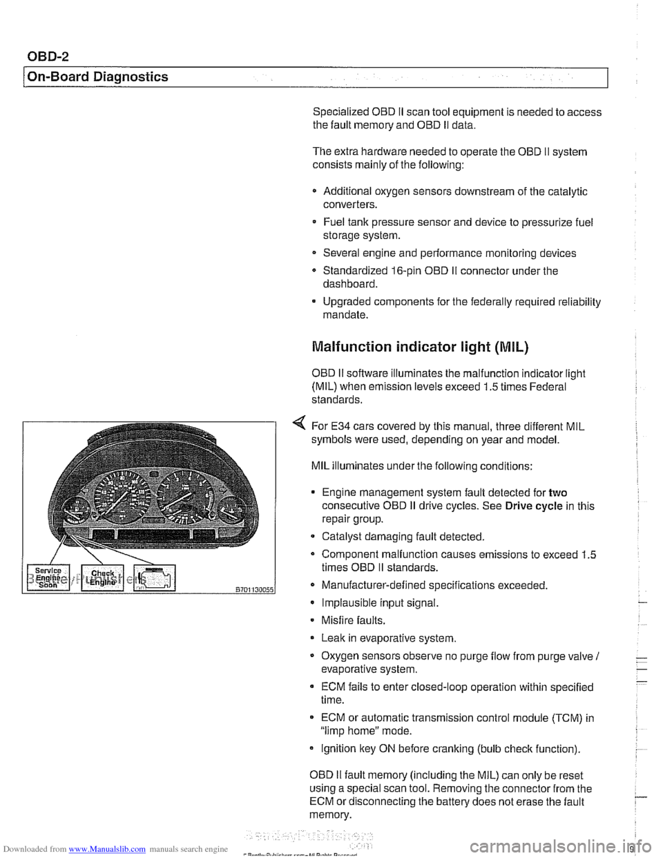
4 For E34 cars covered by this manual, three different MIL
symbols were used, depending on year and model.
MIL illuminates under the following conditions:
Engine management system fault detected for
two
consecutive OED iI drive cycles. See Drive cycle in this
repair group.
- Catalyst damaging fault detected.
Component malfunction causes emissions to exceed 1.5
times OED
II standards.
Manufacturer-defined specifications exceeded. Implausible input signal.
Misfire
faults.
Leak in evaporative system,
Oxygen sensors observe no purge
flow from purge valve 1
evaporative system.
ECM fails to enter closed-loop operation within specified
time.
ECM or automatic transmission control
module (TCM) in
"limp home" mode.
ignition key ON before cranking (bulb
check function).
OED
II fault memory (including the MIL) can only be reset
using a special scan tool. Removing the connector from the
ECM or disconnecting the battery does not erase the fault
memory.
Page 963 of 1002
Downloaded from www.Manualslib.com manuals search engine
OBD-3
On-Board
~iactnosticsl
Additional MIL information:
A fault code is stored within the ECM upon the first
occurrence of a fault in the system being checlted.
Two complete consecutive drive cycles with the iault
present illuminate the MIL. The exception to the two-fault
requirement is a catalyst-damaging fault, which illuminates
the MIL immediately.
If the second drive cycle was not complete and the fault
was not checked, the ECM counts the third drive cycle as
the next consecutive drive cycle. The MIL illuminates
if the
system is checked and the fault is still present.
Once the MIL is illuminated, it remains illuminated until the
vehicle completes three consecutive drive cycles without
detecting a fault.
0 An existing fault code is cleared from memory
automatically when the vehicle completes
40 consecutive
drive cycles without the fault being detected.
In order to automatically clear a catalyst-damaging fault from
memory, the condition underwhich the fault occurred must be
evaluated for 80 consecutive drive cycles without the fault
reoccurring.
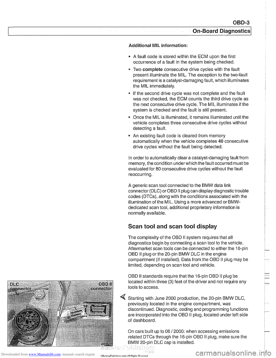
A generic scan tool connected to the BMW data link
connector (DLC) or OBD
I1 plug can display diagnostic trouble
codes (DTCs), along with the conditions associated with the
illumination of the MIL. Using a more advanced or
BMW-
dedicated scan tool, additional proprietary information is
normally available.
Scan tool and scan tool display
The complexity of the OBD I1 system requires that all
diagnostics begin by connecting a scan tool to the vehicle.
Aftermarltet scan tools can be connected to either the 16-pin
OBD
I1 plug or the 20-pin BMW DLC in the engine
compartment
(ii installed). Data from the OBD II plug may be
limited, depending on scan tool and vehicle.
OBD
I1 standards reouire that the 16-oin OBD I1 oluo be
located within three
(3) feet of the driier and not're&ire any
tools to access.
Starting with June 2000 production, the 20-pin BMW DLC,
previously located in the engine compartment, was
discontinued. Diagnostic, coding and programming functions
are incorporated into the OBD
II plug, located under left side
of dashboard.
On cars built up to 06
/ 2000: when accessing emissions
related DTCs through the 16-pin OBD
I1 plug, malte sure the
BMW 20-oin DLC
caD is installed.
Page 964 of 1002
Downloaded from www.Manualslib.com manuals search engine
- -
On-Board Diagnostics
Professional diagnostic scan tools available atthe time of this
printing include the BMW factory tools
(DISplus, GTI,
MoDiC) and a small number of aftermarket BMW-specific
tools. See
020 Maintenance.
In addition to the professional line of scan tools, inexpensive
generic OBD
II scan tool software programs and handheld
units are readily available. Though limited, they are
nonetheless powerful diagnostic tools. These tools read live
data streams and freeze frame data as well as a host of other
valuable diagnostic data.
Diagnostic monitors
Diagnostic monitors run tests and checks on specific
emission control systems, components, and functions.
A complete drive cycle is requiredforthe tests to bevalid. See
Drive cycle in this repair group. The diagnostic monitor
signals the
ECM of the loss or impairment of the signal or
component and determines if a signal or sensor is faulty
based on
3 conditions:
* Signal or component shorted to ground
Signal or component shorted to
B+
Signal or component missing (open circuit)
The OBD
II system monitors all emission control systems that
are installed. Emission control systems vary by vehicle model
and year. For example, a vehicle may not be equipped with
secondary air injection, so no secondary air readiness code
would be present.
OBD
II software monitors the following:
Oxygen sensors
Catalysts
Engine misfire
- Fuel tank evaporative control system
Secondary air injection Fuel system
Oxygen sensor monitoring. When driving conditions allow,
response rate and switching time of each oxygen sensor is
monitored. The oxygen sensor heater function is also
monitored. The OBD
II system differentiates between
precataylst and post-catalyst oxygen sensors and reads each
one individually. In order
forthe oxygen sensor to be
effectively monitored, the system must be in closed loop
operation.
Page 965 of 1002
Downloaded from www.Manualslib.com manuals search engine
On-Board Diagnostics
Catalyst monitoring. Thisstrategy monitors the outputofthe
precatalyst and post-catalyst oxygen sensors, comparing the
oxygen content going into the catalytic converter to the
oxygen leaving the converter.
The diagnostic executive
lknows that most of the oxygen
should be used up during the oxidation phase. If it detects
higherthan programmed values, afault is set and the MIL
illuminates.
Misfire detection. This strategy monitors crankshaft speed
fluctuations and determines if an enoine misfire occurs bv
monitoring variations in speed between each crankshaft
sensortrigger point. This strategy is so finely tuned that it can
determine the severity of the misfire.
The system determines
if a misfire is occurring, as well as
other pertinent misfire
information such as:
Specific
cylinder(s)
Severity of the misfire event
Emissions relevant or catalyst damaging
Misfire detection is an on-going monitoring process that is
only disabled under certain limited conditions.
Secondary air injection monitoring. Secondary air
injection is used to reduce HC and CO emissions during
engine warm up. Immediately following a cold engine start
(-1 0" to 40°C), fresh air (and therefore oxygen) is pumped
directly into the exhaust
manifold. By injecting additional
oxygen into the exhaust manifold, catalyst warm-up time is
reduced.
Secondary air system components are:
Electric air injection pump
* Electric pump relay
* Non-return valve
Vacuum
I vent valve
- Stainless steel air injection pipes
Vacuum reservoir
The secondary air system is monitored via the use
of the pre-
catalyst oxygen sensors. Once the air pump is active and air
is injected into the system, the signal at the oxygen sensor
reflects a lean condition. If the oxygen sensor signal does not
change, a fault is set and the faulty
bank(s) identified. If after
completing the next cold startafault is again present, the MIL
illuminates.