engine BMW 525i 1998 E39 Workshop Manual
[x] Cancel search | Manufacturer: BMW, Model Year: 1998, Model line: 525i, Model: BMW 525i 1998 E39Pages: 1002
Page 651 of 1002
Downloaded from www.Manualslib.com manuals search engine
310-1 5
Front ~us~ension/
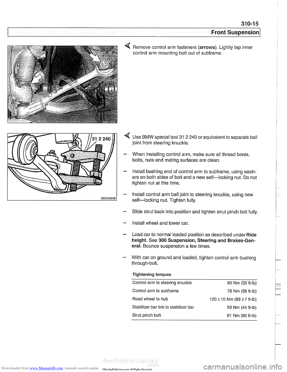
4 Remove control arm fasteners (arrows). Lightly tap inner
control arm mounting bolt out of subframe.
Use
BMW special tool 31 2 240 or equivalent to separate ball
joint from steering knuckle.
When installing control arm, make sure all thread bores,
bolts, nuts and mating surfaces are clean.
lnstall bushing end of control arm to subframe, using wash-
ers on both sides of bolt and a new self-loclting nut. Do not
tighten nut at this time.
lnstall control arm ball joint to steering knuckle, using new
self-locking nut. Tighten fully.
- Slide strut back into position and tighten strut pinch bolt fully.
- Install wheel and lower car.
- Load car to normal loaded position as described under Ride
height. See
300 Suspension, Steering and Brakes-Gen-
eral. Bounce suspension a few times.
- With car on ground and loaded, tighten control arm bushing
through-bolt.
Tightening torques
Control arm to steering knuckle 80 Nm
(59 ft-lb)
Control arm to
subframe 78 Nm (58 ft-lb)
Road wheel to hub
120
f 10 Nm (89 +7 ft-lb)
Stabilizer bar
link to stabilizer bar
59 Nm (44 fl-lb)
Strut pinch bolt
81 Nm (60 it-lb)
Page 652 of 1002
Downloaded from www.Manualslib.com manuals search engine
I Front Suspension
Tension strut, removing
and installing
- Raise car and remove wheel.
WARNING-
Make sure that the car is firmly supported on jack stands de-
signed for the purpose. Place jack stands underneath struc-
tural chassis points. Do not place
jack stands under
suspension parts.
- Remove engine splash shield
6-cylinder models: Remove
brake cooling duct.
V-8 models: Detach stabilizer bar from front subframe.
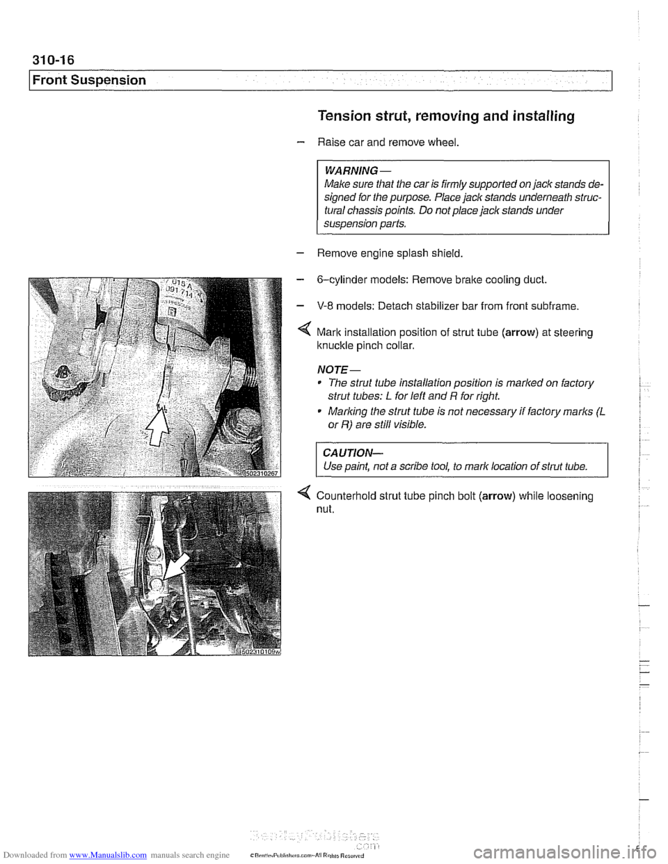
Mark installation position of strut tube (arrow) at steering
ltnuckle pinch collar.
NOJE-
* The strut tube installation position is marlted on factory
strut tubes:
L for left and R for right.
* Marlting the strut tube is not necessary if factory marks (L
or R) are still visible.
CAUJION-
Use paint, not a scribe tool, to mark location of strut tube. 1
4 Counterhold strut tube pinch bolt (arrow) while loosening
nut.
Page 653 of 1002
Downloaded from www.Manualslib.com manuals search engine
31 0-1 7
Front ~uspensionl
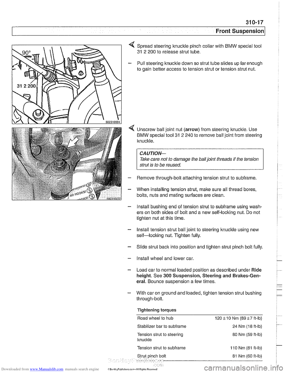
< Spread steering knuckle pinch collar with BMW special tool
31 2 200 to release strut tube.
- Pull steering knuckle down so strut tube slides up farenough
to gain better access to tension strut or tension strut nut.
4 Unscrew ball joint nut (arrow) from steering knuckle. Use
BMW special tool
31 2 240 to remove ball joint from steering
Iknucltle.
CAUTION--
Tale care not to damage the balljoint threads if the tension
strut
is to be reused.
- Remove through-bolt attaching tension strut to subframe.
- When installing tension strut, make sure all thread bores,
bolts, nuts and mating
suriaces are clean.
- Install bushing end of tension strut to subframe using wash-
ers on both sides of bolt and a new self-locking nut. Do not
tighten nut at this time.
- Install tension strut ball joint to steering knuckle using new
self-locking nut. Tighten fully.
- Slide strut back into position and tighten strut pinch bolt fully.
- Install wheel and lower car.
- Load car to normal loaded position as described under Ride
height. See
300 Suspension, Steering and Brakes-Gen-
eral. Bounce suspension a few times.
- With car on ground and loaded, tighten tension strut bushing
through-bolt.
Tightening torques Road
wheel to hub 120-i-10 Nm (89+7ft-lb)
Stabilizer bar to subframe 24 Nm (1 8 ft-lb)
Tension strut to steering
knucltle
80 Nm (59 ft-lb)
Tension strut
to subframe 110 Nm (81 ft-lb)
81 Nm (60 it-lb)
L BcniliiyFlrblrillirn con,-*I R!,illJ Rci,:n>d
Page 654 of 1002
Downloaded from www.Manualslib.com manuals search engine
31 0-1 8
I~ront Suspension Tension strut bushing, replacing
- Raise car and remove wheel.
WARNING-
Make sure that the caris firmly supported on jack stands de-
signed for the purpose. Place jack stands underneath struc-
tural chassis points. Do
not place jack stands under
suspension parts.
- Remove tension strut from car as described earlier.
- Using a service press and appropriate press tools (BMW
special tools 31 2 26112621263 or equivalent), press bushing
out of tension strut.
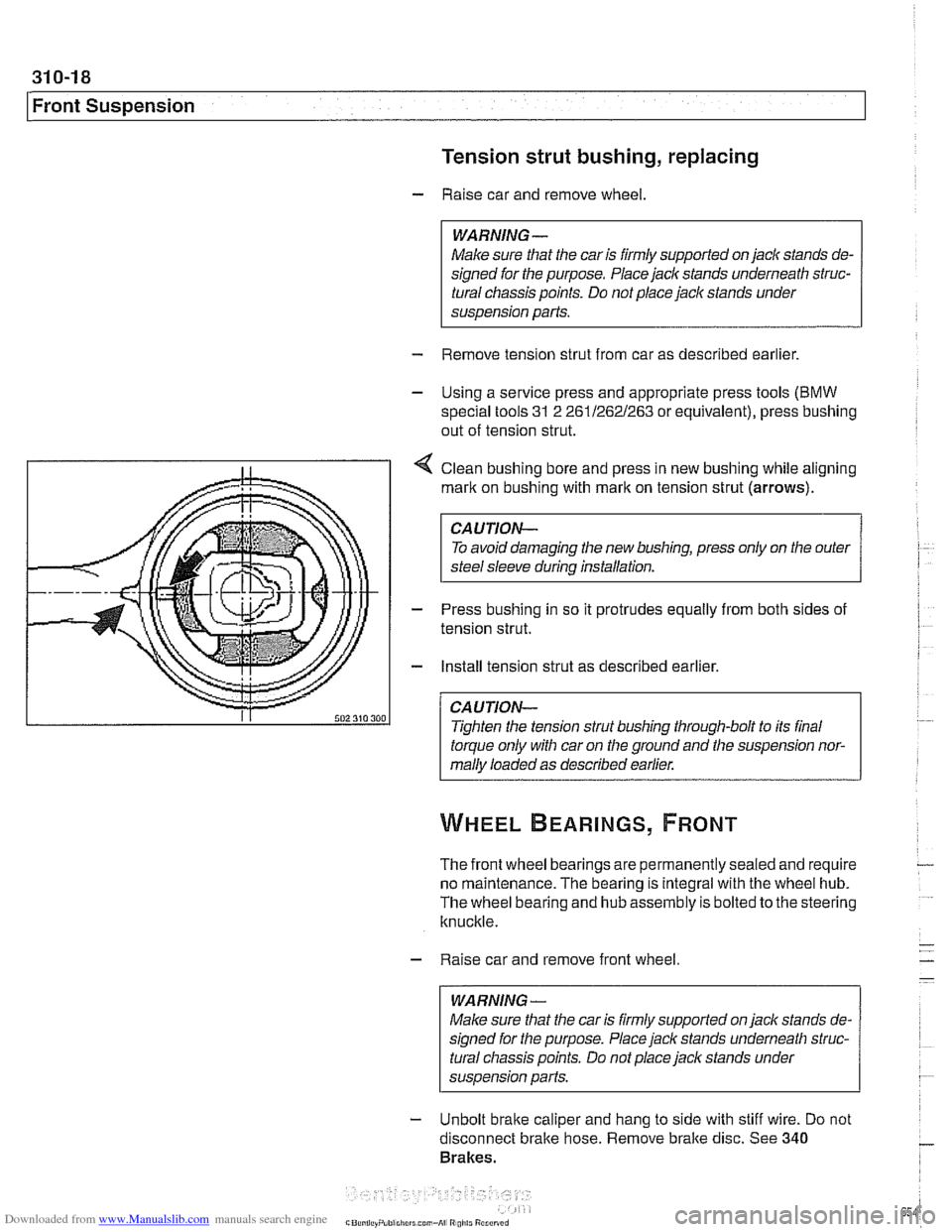
4 Clean bushing bore and press in new bushing while aligning
mark on bushing with
rnarlt on tension strut (arrows).
CAUTION-
To avoid damaging the new bushing, press only on the outer
steel sleeve during installation.
- Press bushing in so it protrudes equally from both sides of
tension strut.
- Install tension strut as described earlier.
CAUTION-
Tighten the tension strut bushing through-bolt to its final
torque only with car on the ground and the suspension nor-
mally loaded as described earlier.
The front wheel bearings are permanently sealed and require
no maintenance. The bearing is integral with the wheel hub.
The wheel bearing and hub assembly is bolted to the steering
knuckle.
- Raise car and remove front wheel
WARNING-
Make sure that the car is firmly supported on jack stands de-
signed for the purpose. Place jack stands underneath struc-
tural chassis points. Do not place
jack stands under
susoension Darts.
- Unbolt brake caliper and hang to side with stiff wire. Do not
disconnect bralte hose. Remove bralte disc. See
340
Brakes.
Page 655 of 1002
Downloaded from www.Manualslib.com manuals search engine
Front Suspension
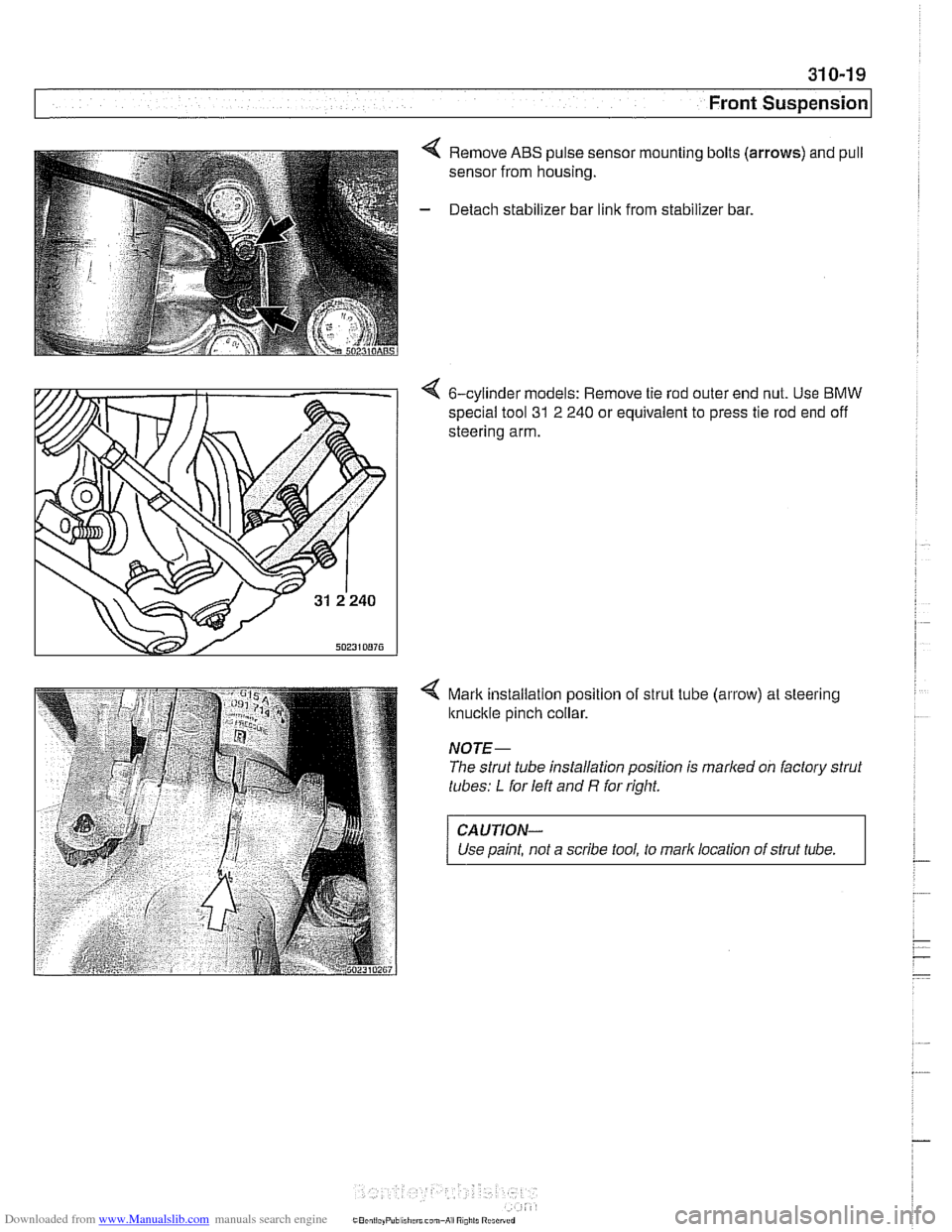
4 Remove ABS pulse sensor mounting bolts (arrows) and pull
sensor from housing.
- Detach stabilizer bar link from stabilizer bar.
4 6-cylinder models: Remove tie rod outer end nut. Use BMW
special tool
31 2 240 or equivalent to press tie rod end off
steering arm.
4 Mark installalion position of strut tube (arrow) at steering
knuckle pinch collar.
NOTE-
The strut tube installation position is marked on factory strut
tubes:
L for left and R for right.
CAUTION-
Use paint, not a scribe tool, to mark location of strut tube.
Page 656 of 1002
Downloaded from www.Manualslib.com manuals search engine
31 0-20
Front Suspension
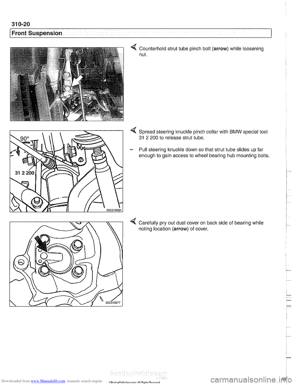
Counterhold strut tube
nut. pinch
bolt (arrow) while loosening
4 Spread steering ltnuckle pinch collar with BMW special tool
31 2 200 to release strut tube.
- Pull steering knuckle down so that strut tube slides up far
enough to gain access to wheel bearing hub mounting bolts.
Carefully pry out dust cover on back side of bearing while
noting location
(arrow) of cover.
Page 657 of 1002
Downloaded from www.Manualslib.com manuals search engine
31 0-21
Front Suspension
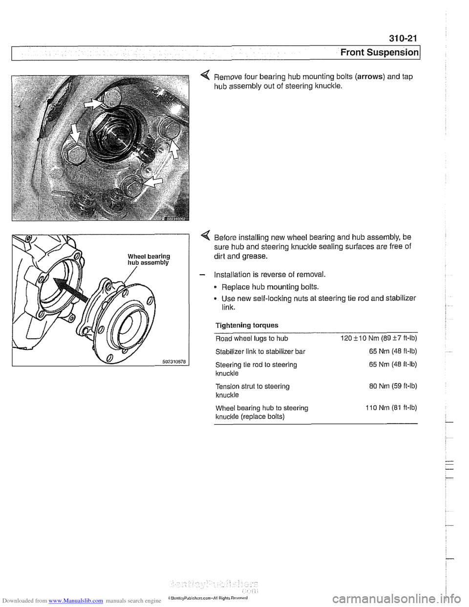
4 Remove four bearing hub mounting bolts (arrows) and tap
hub assembly out of steering knuckle.
4 Before installing new wheel bearing and hub assembly, be
sure hub and steering knuckle sealing surfaces are free of
dirt and grease.
- Installation is reverse of removal.
Replace hub mounting bolts.
Use new self-locking nuts at steering tie rod and stabilizer
link.
Tightening
torques
Road wheel lugs to hub 120i-10 Nm (89i-7ft-lb)
Stabilizer link to stabilizer bar
Steering tie rod to steering
ltnuckle
Tension strut to steering
knucltie
Wheel bearing hub to steering
Itnucltle (replace bolts)
65 Nm (48 ft-lb)
65
Nm (48 it-lb)
80 Nm (59 ft-lb)
1
lo Nm (81 ft-lb)
Page 658 of 1002
Downloaded from www.Manualslib.com manuals search engine
31 0-22
I Front Suspension
Stabilizer bar, removing and installing
On E39 models the front stabilizer bar links attach to the strut
assemblies.
- Raise car and support safely.
Male sure that the car is firmly supported on jack stands de-
signed for the purpose. Place jack stands underneath struc-
tural chassis points. Do not place jaclc stands under
suspension parts.
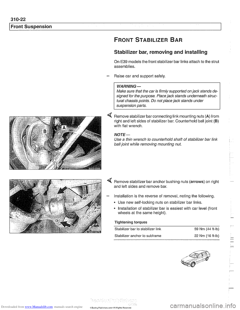
< Remove slaol zer bar connecring I nk rnounl ng nLts (A) from
r~glit and eft s~des of slaol lzer bar C~~nIerhol~ ball ]olnl (6)
with flat wrench
NOTE-
Use a thin wrench to counterhold shaft of stabilizer bar link
ball joint while removing mounting nut.
< Remove stabilizer bar anchor bushing nuts (arrows) on right
and left sides and remove bar.
- Installation is the reverse of removal, noting the following.
Use new self-locking nuts on stabilizer bar links.
Installation of stabilizer bar is easiest with car level (front
wheels at the same height).
Tightening torques Stabilizer bar to stabilizer link
59 Nm (44 ft-lb)
Stabilizer anchor to subframe 22 Nm (16 ft-lb)
Page 659 of 1002
Downloaded from www.Manualslib.com manuals search engine
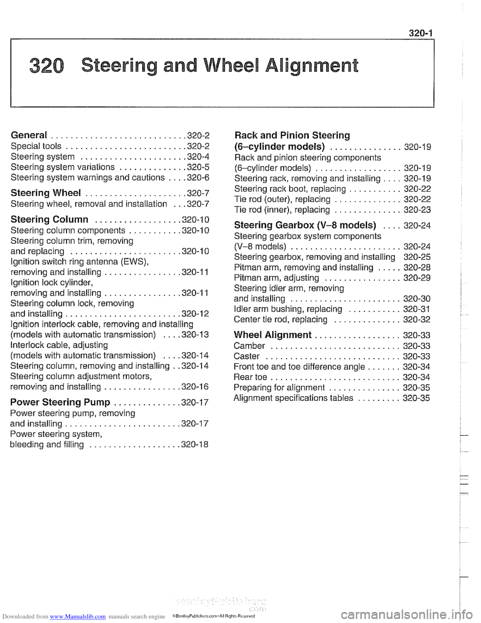
1 320 Steering and Wheel Alignment
General ........................... .32 0.2
Special tools
........................ .32 0.2
Steering system
..................... .32 0.4
Steering system variations
............. .32 0.5
Steering system warnings and cautions
... .32 0.6
Steering Wheel .................... .32 0.7
Steering wheel. removal and installation
.. .32 0.7
Steering Column ................. .32 0.1 0
Steering column components .......... .32 0.10
Steering column trim, removing
and replacing
...................... .32 0.10
lgnition switch ring antenna (EWS).
removing and installing
............... .32 0.1 1
lgnition lock cylinder.
removing and installing
............... .32 0-1 1
Steering column lock. removing
and installing
....................... .32 0.12
lgnition
interloclc cable. removing and installing
(models with automatic transmission)
... .32 0.13
Interlock cable. adjusting
(models with automatic transmission)
... .32 0.14
Steering column. removing and installing
. .32 0.14
Steering column adjustment motors.
removing and installing
............... .32 0.16
Power Steering Pump ............. .32 0.17
Power steering pump. removing
and installing
....................... .32 0.1 7
Power steering system.
bleeding and filling
.................. .32 0.18
Rack and Pinion Steering
(6-cylinder models)
............... 320-19
Rack and pinion steering components
(6-cylinder models)
.................. 320-1 9
Steering rack. removing and installing
.... 320-19
Steering
rack boot. replacing ........... 320-22
Tie rod (outer). replacing
.............. 320-22
Tie rod (inner). replacing
.............. 320-23
Steering Gearbox (V-8 models) .... 320-24
Steering gearbox system components
. .
(V-8 models) ....................... 320-24
Steering gearbox, removing and installing 320-25
Pitman arm. removing and installing ..... 320-28
Pitman arm. adjusting ................ 320-29
Steering idler arm. removing
and installing
....................... 320-30
Idler arm bushing. replacing ........... 320-31
Center tie rod. replacing
.............. 320-32
Wheel Alignment .................. 320-33
Camber
........................... 320-33
Caster
............................ 320-33
Front toe and toe difference angle
....... 320-34
Reartoe ........................... 320-34
Preparing for alignment
............... 320-35
Alignment specifications tables
......... 320-35
Page 660 of 1002
Downloaded from www.Manualslib.com manuals search engine
I Steering and Wheel Alignment
This repair group covers steering wheel and column removal
and steering system service, including wheel alignment infor-
mation.
NOTE-
Ignition loclc cylinder replacement is covered in this sec-
tion.
a For information on steering column mounted switches, in-
cluding the ignition switch, see
612 Switches.
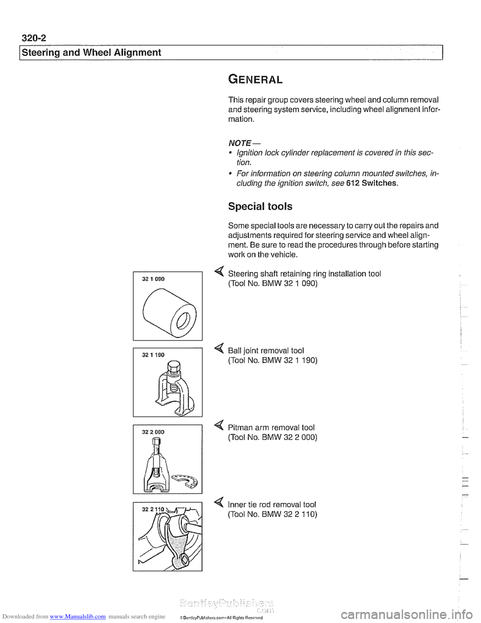
Special tools
Some special tools are necessary to carry out the repairs and
adjustments required for steering service and wheel align-
ment. Be sure to read the procedures through before starting
work on the vehicle.
4 Steering shafl retaining ring installation tool
(Tool No. BMW 32
1 090)
4 Bail joint removal tool
(Tool No. BMW 32
1 190)
4 Pitman arm removal tool
(Tool No. BMW 32 2
000)
4 Inner tie rod removal tool
(Tool No. BMW 32 2
110)