driver BMW 525i 1998 E39 Repair Manual
[x] Cancel search | Manufacturer: BMW, Model Year: 1998, Model line: 525i, Model: BMW 525i 1998 E39Pages: 1002
Page 949 of 1002
Downloaded from www.Manualslib.com manuals search engine
721 Airbag System (SRS)
........................... General ............................ 721-2 Airbags 721-8
..... E39Airbags ......................... 721-3 Driver airbag. removing and installing 721-8
Two-stage airbag (MRS 111) ............ .72 1.4 Passenger airbag. removing and installing . 721-9
Airbag indicator light .................. .72 1.4 Door mounted side-impact airbag.
............... Warninas .......................... .72 1.5 removina and installina 721-10 .
..... Head protection airbag components 721
-1 1 Airbag Electronics ................. '721-6 Head protection airbag (HpS) .......... 721-12 MRS ............................... 721-6
MRS
airbag system diagram ........... .72 1.6
MRS control module. replacing ......... .72 1.7
Side-impact crash sensor.
removing and installing
................ .72 1.7
Page 950 of 1002
Downloaded from www.Manualslib.com manuals search engine
721 -2
l~irba~ System (SRS)
This repair group covers airbag components and replace-
ment.
Airbag system repairand fault diagnosis is not covered.
Diagnostics, component testing, and
airbag system repair
should be carried out by trained BMW service technicians.
Individual
airbag system components can only be tested elec-
tronically when installed in the car. BMW service testers
DIS
or MoDiC or equivalent must be used for diagnostic work.
WARNING-
Special test equipment is required to retrieve airbag fault
codes, diagnose system faults, and
reseffturn off the air-
bag indicator light. The indicator light will remain on until
any problem has been corrected and the fault memory has
been cleared.
Airbags are part of the BMW Multiple Restraint System
(MRS). Three versions of MRS are available in E39 models.
Multiple Restraint Systems
MRS and MRS II include the following restraint components:
311 996-811 997
911
997-311 999
311 999-2002
Driver and passenger front
airbags (MRSIMRS II)
MRS
MRS
II
MRS Ill
Passenger front two-stage airbag (cars manufactured
from
911998).
The seat occupancy sensor (SBE) is used for detection of
a passenger in the right front seat. MRS uses the SBE in-
put to determine seat belt tensioner
and/or front airbag de-
ployment thresholds.
Side impact
airbag for driver and front passenger
(MRSIMRS II)
Leftlright side impact crash sensors (MRSIMRS 11)
Side impact airbag for rear passenger (MRS II) (optional)
Head Protection System (HPS) for driver and front passen-
ger (MRS
II)
Battery Safety Terminal - BST (MRS II)
Hall Sensor seat belt switches (MRS II)
Front pyrotechnic seat belt tensioners
Fuel pump cut off message
Page 951 of 1002
Downloaded from www.Manualslib.com manuals search engine
721 -3
Airbag System (SRS)
MRS Ill adds the following features:
MRS
Ill employs "smart" technology. Smart technology re-
fers to the control module's programming for the deploy-
ment of the airbags, in stages depending on the severity of
the impact.
Two-stage a~rbag for ooln drver and passenger Alloivs for
a softer
c~snioning elfecl when the airbags are lr ggered at
lighter impact,
MRS
Ill satellite sensors use 2 wire connectors
Rear side
airbags arrive de-activated from the factory and
can only be activated upon written request from the cus-
tomer.
Rear seat head protection is available when ordered with
optional rear seat side airbags.
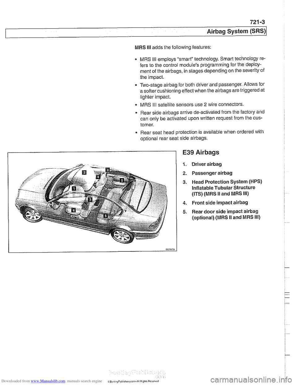
E39 Airbags
Driver airbag
Passenger airbag
Head Protection System (HPS)
Inflatable Tubular Structure
(ITS) (MRS
II and MRS Ill)
Front side impact airbag
Rear door side impact airbag
(optional) (MRS I1 and MRS Ill)
Page 954 of 1002
Downloaded from www.Manualslib.com manuals search engine
721-6
I Airbag System (SRS)
MRS
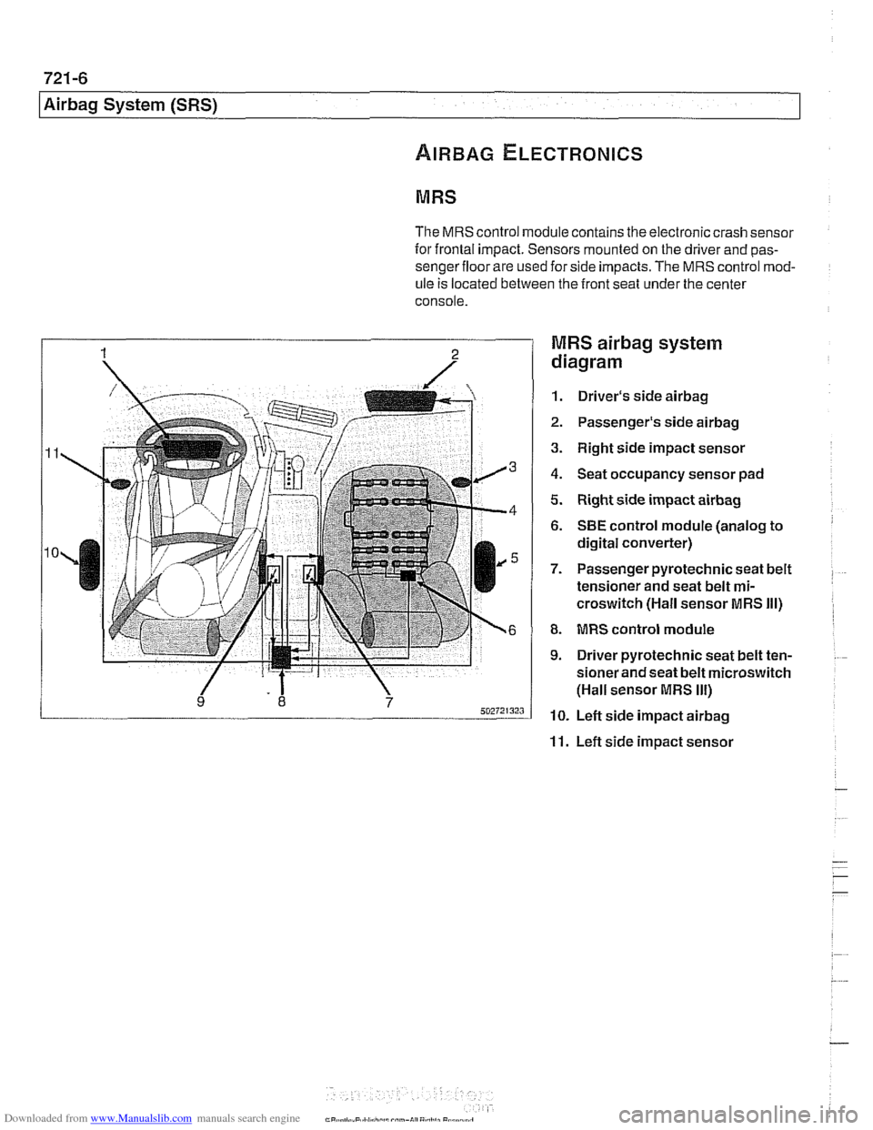
The MRS control module contains the electronic crash sensor
for frontal impact. Sensors mounted on the driver and
pas-
sengerfloor are used for side impacts. The MRS control mod-
ule
is located between the front seat under the center
console.
MRS airbag system
diagram
1. Driver's side airbag
2. Passenger's side airbag
3. Right side impact sensor
4. Seat occupancy sensor pad
5. Right side impact airbag
6. SBE control module (analog to
digital converter)
7. Passenger pyrotechnic seat belt
tensioner and seat belt
mi-
croswitch (Hall sensor MRS Ill)
8. MRS control module
9. Driver pyrotechnic seat belt ten-
sioner and seat belt microswitch
(Hall sensor MRS
Ill)
10. Left side impact airbag
11. Left side impact sensor
Page 956 of 1002
Downloaded from www.Manualslib.com manuals search engine
721 -8
(Airbag System (SRS)
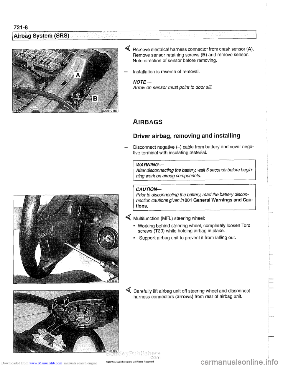
4 Remove electrical harness connector from crash sensor (A).
Remove sensor retaining screws (6) and remove sensor.
Note direction of sensor before removing.
- Installation is reverse of removal,
NOTE -
Arrow on sensor must point to door sill.
Driver airbag, removing and installing
- Disconnect negative (-) cable from battery and cover nega-
tive terminal with insulating material.
WARNING-
After disconnecting the batter)! wait 5 seconds before begin-
ning work on
airbag components.
CAUTION-
Prior to disconnecting the batter)! read the battery discon-
nection cautionsgiven
in001 General Warnings and Cau-
tions.
4 Multifunction (MFL) steering wheel:
. Working behind steering wheel, completely loosen Torx
screws
(T30) while holding airbag in place.
Support
airbag unit to prevent it from falling out.
Page 957 of 1002
Downloaded from www.Manualslib.com manuals search engine
721 -9
Airbaq System ~SRS)~
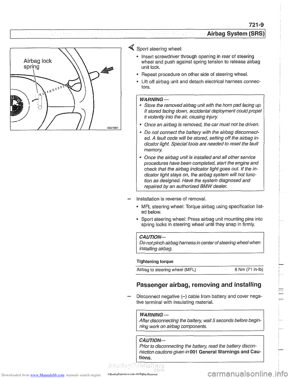
4 Sport steering wheel:
Insert screwdriver through opening in rear of steering
wheel and push against spring tension to release
airbag
unit lock.
Repeat procedure on other side of steering wheel.
Lift off
airbag unit and detach electrical harness connec-
tors.
WARNING-
Store the removedairbag unit with the horn pad facing up.
If stored facing down, accidental deployment could propel
it violently into the air, causing injury.
Once an
airbag is removed, the car must not be driven.
Do not connect the battery with the
airbag disconnect-
ed. A fault code will be stored, setting off the
airbag in-
dicator light Special tools are needed to reset the fault
memory
Once the
airbag unit is installed and all other service
procedures have been completed, start the engine and
check that the
airbag indicator light goes out. If the in-
dicator light stays on, the
airbag system will not func-
tion as designed. Have the system diagnosed and
repaired by an authorized
BMW dealer.
- Installation is reverse of removal.
MFL steering wheel: Torque airbag using specification list-
ed below.
- Sport steering wheel: Press airbag unit mounting pins into
spring
loclts in steering wheel until they snap in firmly.
CAUTION--
Do notpinch airbag harness in center of steering wheel when
installino
airbaa.
Tightening torque
Airbao to steerino wheel IMFL) 8 Nm (71 in-lb)
Passenger airbag, removing and installing
- Disconnect negative (-) cable from battery and cover nega-
tive terminal with insulating material.
--
WARNING -
After disconnecting the batteg wait 5 seconds before begin-
nina work on airbaa components.
Prior to disconnecting the battery, read the battery discon-
nection cautionsgiven in001 General Warnings and
Cau-
Page 991 of 1002
Downloaded from www.Manualslib.com manuals search engine
INDEX 'tl
WARNING
Your common sense, good
judgemenl, and general alertness are
crucial to sale and successiul service
worlr. Belore attempting any work on
your
BMM be sure lo read 001
General Warnings and Cautions
and the
copyriglll page at the front 01
the manual. Review these warnings
and
caulions each lime you prepare
lo work on your BMW. Please also
read any warnings and cautions that
accompany
tile procedures in the
manual.
312-way valve (running losses)
see Fuel tank
Abbreviations, commonly used 600-14
ABS (antilock brake system)
see
Bral(es
A/C air distribution motors
see stepper motors (below)
blower final stage (resistor pack),
replacing
640-16
blower, removinglinslalling
640-1 5
compressor, replacing
640-24 condenser, replacing 64045
control panellmodule, removing1
installing
640-1 1
evaporakr, removinglinstalling 640-29
evaporator temperature sensor
640-12 expansion valve, removinglinstailing
640-27
IHKA/ IHKR system description 640-5
receiveridrier, replacing 640-26
stepper motors 640-1 3 ventilation microiilter, replacing
020-22. 640-17
see also Heating
Accelerator
iinlcage
see Maintenance
Activated carbon canister
see Fuel tank
ADS (auxiliary throttle valve)
130-57
Air compressor
330-44
Air conditioning
see
AIC
Air distribution (flap) motors
seeNC, stepper motors
Air filter see Maintenance
Air spring
300-6, 330-12
Airbag system (SRS)
2-stage
airbag 721-4
control module, replacing 721-7 driver airbag, removinglinstalling
721-8
iiead protection airbag 721-12 components 721-1 1
indicator
lighl721-4
passenger airbag, removinglinstalling
721-9 side-impact airbags crash sensor,
replacing
721-7
Airflow sensor see 130 under appropriate
fuel
injection system
Air pump
see 130 under appropriate fuel
injection system, secondary air
injection system
Air suspension
see Electronic height control
(EHC)
Alarm
see Anti-theft alarm
Alignment see
Wheei alignment
Aluminum suspension components
300-2
Antenna 650-6
Alternator see Battery, starter, alte rnator
Amplifier
650-4
Anti-theft alarm (DWA)
515-24 emergency disarming 515-31
Antifreeze (engine coolant)
see Maintenance
see also Cooling system
Antilock brake system (ABS) see Brakes
ASC see Brakes
ATF (automatic transmission fluid)
see Automatic transmission
see also Cooling systern
Automatic headlight adjustmenl
(LWR) see Lights
Automatic seat belt tensioner
720-4
Automatic shiftloclc
see
Gearshift
Automatic transmission
applications
200-3, 240-4
ATF 020-10, 200-4
capacity 240-8 checking 240-6
drainingifilling 240-7
heat exchanger 170-5
fluid pan and strainer 240-9 gearshift
see Gearshift
ID tag
200-3 range switch 610-6
removaliinstallation 240-10
steptronic see Gearshift
Auxiliary cooling fan
see
Coollng system, electric Ian
Auxiliary throttle valve (ADS)
130-57
Axle joint
see Drive axle
Back-up light switch
automatic transmission see Automatic transmission. range switch
- .~.~~~
manual transmission 230-8 -
- I