Remove starter BMW 525i 1999 E39 Workshop Manual
[x] Cancel search | Manufacturer: BMW, Model Year: 1999, Model line: 525i, Model: BMW 525i 1999 E39Pages: 1002
Page 74 of 1002
Downloaded from www.Manualslib.com manuals search engine
I Engine Removal and Installation
Engine removal and installation are covered in this repail
group.
See 100 Engine-General for engine identification details
and engine codes.
Transmission removal is required for all models before the
engine can be removed. This is best accomplished with the
car raised on an automotive lift. For additional procedures re-
quired during engine removal, refer to the following repair
groups:
020 Maintenance
0 121 Battery, Alternator, Starter
170 Radiator and Cooling System
180 Exhaust System
4 230 Manual Transmission
0 240 Automatic Transmission
410 Fenders, Engine Hood
Special tools
Some special tools are required for engine removal and in-
stallation. Be sure to have the necessary equipment on hand
before starting the job.
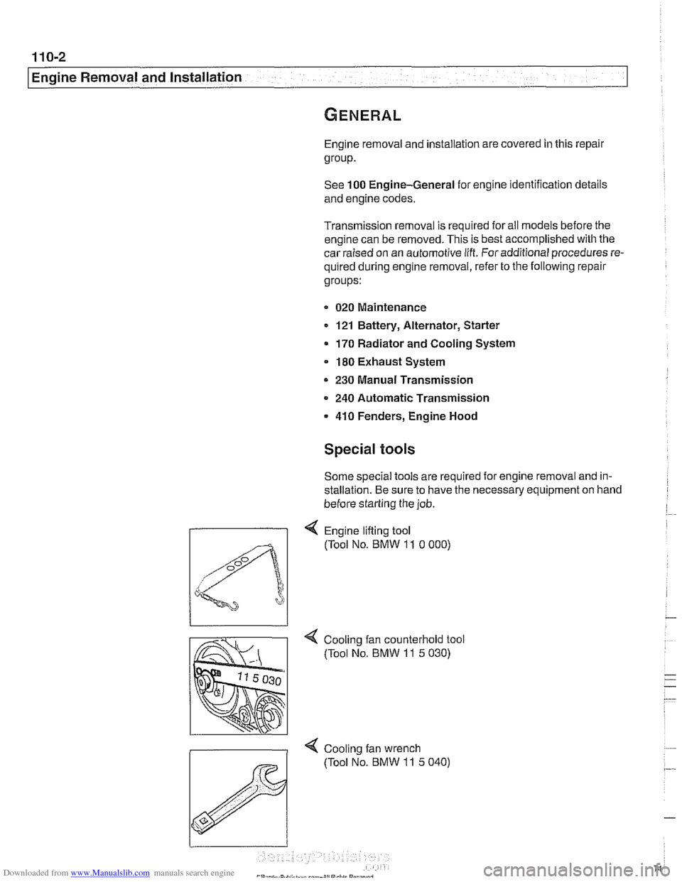
Engine lifting tool
(Tool No. BMW
11 0 000)
4 Cooling fan counterhold tool
(Tool No. BMW
11 5 030)
< Cool~ng fan wrench
(Tool No. BMW
11 5 040)
Page 82 of 1002
Downloaded from www.Manualslib.com manuals search engine
.-
-6val and Installation -
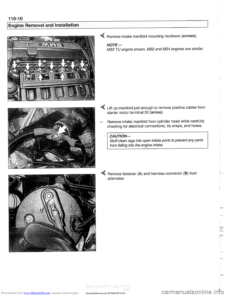
< Remove intake manifold mounting hardware (arrows).
NOTE-
M52 TU engine shown. M52 and M54 engines are similar.
Liit up manifold just enough to remove positive cables from
starter motor terminal
50 (arrow).
- Remove intake manifold from cylinder head while carefully
checking for electrical connections, tie wraps, and hoses.
CAUTION-
Stuff clean rags into open intake ports to prevent any parts
from falling into the engine intake.
4 Remove fastener (A) and harness connector (B) from
alternator.
Page 84 of 1002
Downloaded from www.Manualslib.com manuals search engine
110-12
Engine Removal and Installation
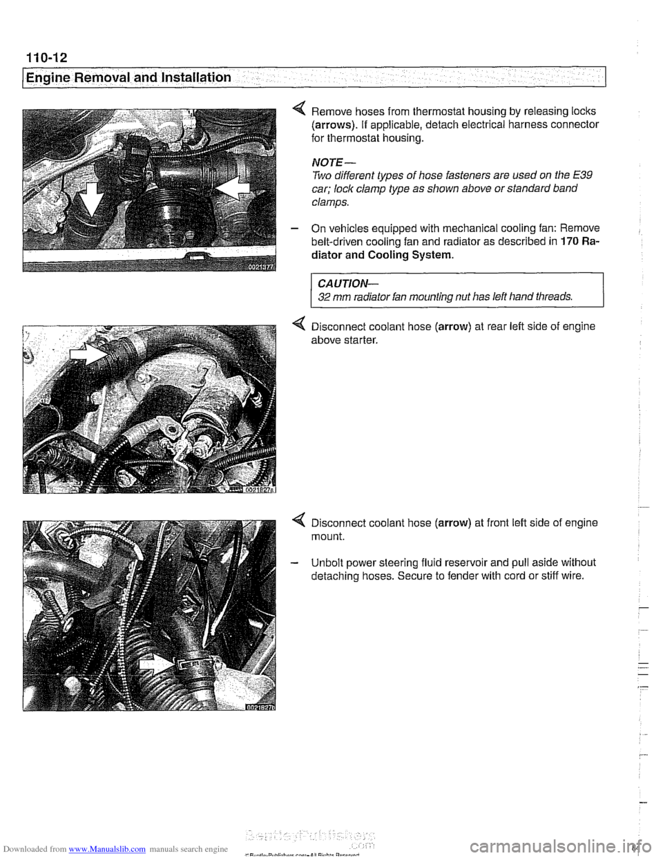
4 Remove hoses from thermostat housing by releasing locks
(arrows). If applicable, detach electrical harness connector
for thermostat housing.
NOTE-
Two different types of hose fasteners are used on the E39
car; lock clamp type as shown above or standard band
clamps.
- On vehicles equipped with mechanical cooling fan: Remove
belt-driven cooling fan and radiator as described in
170 Ra-
diator and Cooling
System.
CAUTION-
32 mm radiator fan mounting nut has left hand threads.
4 Disconnect coolant hose (arrow) at rear left side of engine
above starter.
4 Disconnect coolant hose (arrow) at front left side of engine
mount.
- Unbolt power steering fluid reservoir and pull aside without
detaching hoses. Secure to fender with cord or stiff wire.
Page 92 of 1002
Downloaded from www.Manualslib.com manuals search engine
11 0-20
Engine Removal and Installation
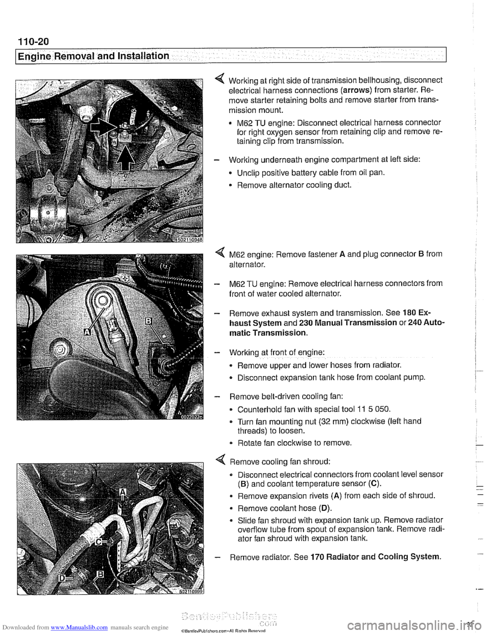
Working at right side of transmission bellhousing, disconnect
electrical harness connections (arrows) from starter. Re-
move starter retaining bolts and remove starter from trans-
mission mount.
M62 TU engine: Disconnect electrical harness connector
for right oxygen sensor from retaining clip and remove re-
taining clip from transmission.
- Working underneath engine compartment at left side:
Unclip positive battery cable from oil pan.
. Remove alternator cooling duct.
4 M62 engine: Remove fastener A and plug connector B from
alternator.
- M62 TU engine: Remove electrical harness connectors from
front of water cooled alternator.
- Remove exhaust system and transmission. See 180 Ex-
haust System and 230 Manual Transmission or 240 Auto-
matic Transmission.
- Working at front of engine:
Remove upper and lower hoses from radiator.
D~sconnect expansion tank hose from coolant pump.
- Remove belt-driven cooling fan:
Counterhold fan with special tool
11 5 050.
Turn fan mounting nut (32 mm) clockwise (left hand
threads) to loosen.
Rotate fan clockwise to remove.
Remove cooling fan shroud:
Disconnect electrical connectors from coolant level sensor
(B) and coolant temperature sensor (C).
. Remove expansion rivets (A) from each side of shroud
Remove coolant hose
(D).
Slide fan shroud with expansion tank up. Remove radiator
overflow tube from spout of expansion tank. Remove radi-
ator fan shroud with expansion tank.
Remove radiator. See
170 Radiator and Cooling System.
Page 100 of 1002
Downloaded from www.Manualslib.com manuals search engine
11 3-6
Cylinder Head Removal and Installation
- Disable ignition system by removing DME main relay. See
610 Component Locations for relay location.
WARNING-
. The ignition system produces high voltages that can be fa-
tal. Avoid contact with exposed terminals and use
exfreme
caution when working on a car with the ignition switched on
or the engine running.
Do not touch or disconnect ignition
components while
the engine is running or being cranked by the starter.
Failure to remove the DME main relay or attempting to
disa-
bie the fuel andignition systems by other methods may result
in damaoe to the enoine control module
(ECM).
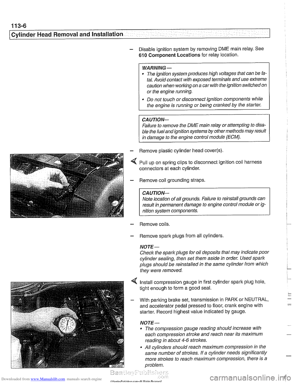
- - Remove plastic cylinder head cover(s)
,,I . ,. .*,.,,&- - Remove coil grounding straps.
I CAUTION-
I nition system components. I
- Remove coils.
- Remove spark plugs from all cylinders.
NOTE-
Check the spark plugs for oil deposits that may indicate poor
cylinder sealing, then set them aside in order. Used spark
plugs should be reinstalled in the same cylinder from which
they were removed.
4 Install compression gauge in first cylinder spark plug hole,
tight enough to form a good seal.
- With parking brake set, transmission in PARK or NEUTRAL,
and accelerator pedal pressed to floor, crank engine with
starter. Record highest value indicated by gauge.
NOTE-
* The compression gauge reading should increase with
each compression stroke and reach near its maximum
reading in about
4-6 strokes.
All cylinders should reach maximum compression in the
same number of
strolces. If a cylinder needs significantly
more strokes to reach
maximum compression, there is a
problem.
Page 107 of 1002
Downloaded from www.Manualslib.com manuals search engine
- - , -. I Cylinder Head Removal and lnstallatio~
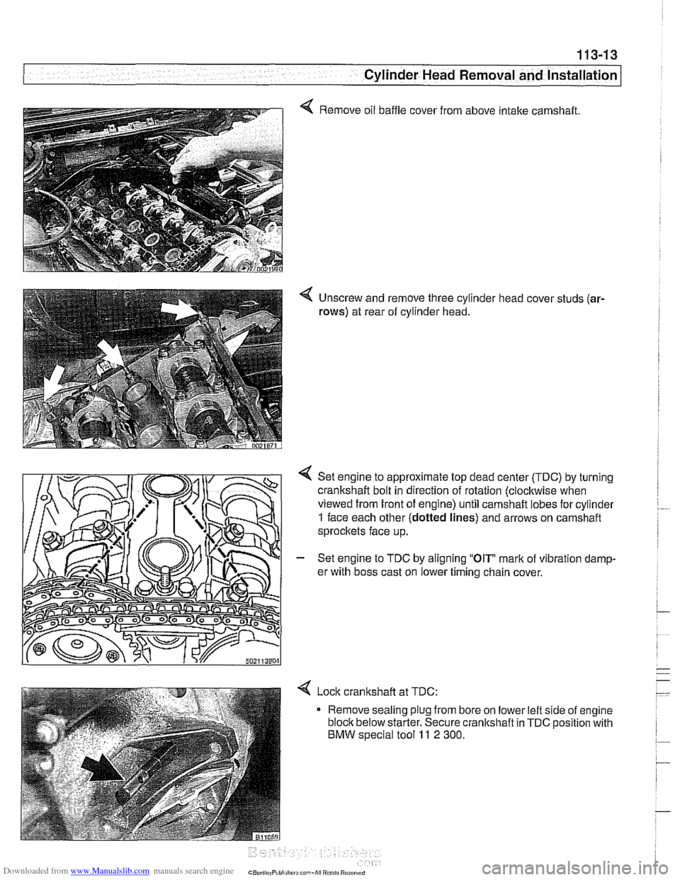
4 Remove oil baffle cover from above intake camshaft.
4 Unscrew and remove three cylinder head cover studs (ar-
rows)
at rear of cylinder head.
Set engine to approximate top dead center
(TDC) by turning
crankshaft bolt in direction of rotation (clocltwise when
viewed from front of engine) until camshaft lobes for cylinder
1 face each other (dotted lines) and arrows on camshaft
sprocltets face up.
- Set engine to TDC by aligning "OIP mark of vibration damp-
er with boss cast on lower timing chain cover.
< Lock cranltshaft at TDC:
Remove sealing plug from bore on lower left side of engine
block below starter. Secure crankshaft in
TDC position with
BMW special tool 11 2 300.
Page 252 of 1002
Downloaded from www.Manualslib.com manuals search engine
Camshaft Timing Chain -- - -1
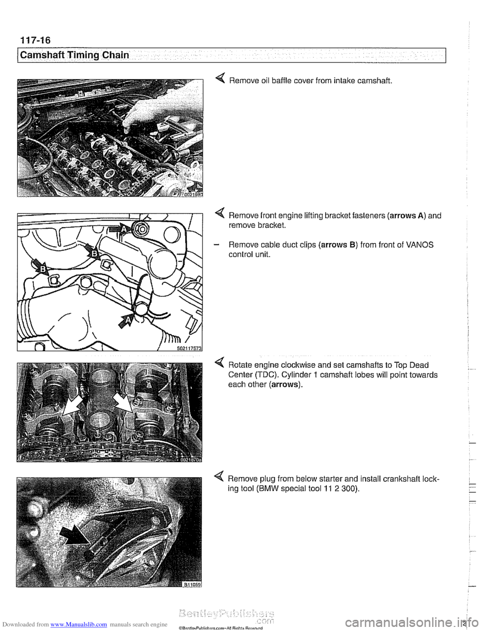
Q Remove oil baffle cover
from intake
camshaft
Remove front engine lifting bracket fasteners (arrows
A) and
remove bracket.
- Remove cable duct clips (arrows B) from front of VANOS
control unit.
Rotate engine
clocltwise and set camshafts to Top Dead
Center (TDC). Cylinder
1 camshaft lobes will point towards
each other (arrows).
4 Remove plug from below starter and install crankshaft lock-
ing tool
(BMW special tool 11 2 300).
Page 275 of 1002
Downloaded from www.Manualslib.com manuals search engine
11 7-39
Camshaft Timing Chain
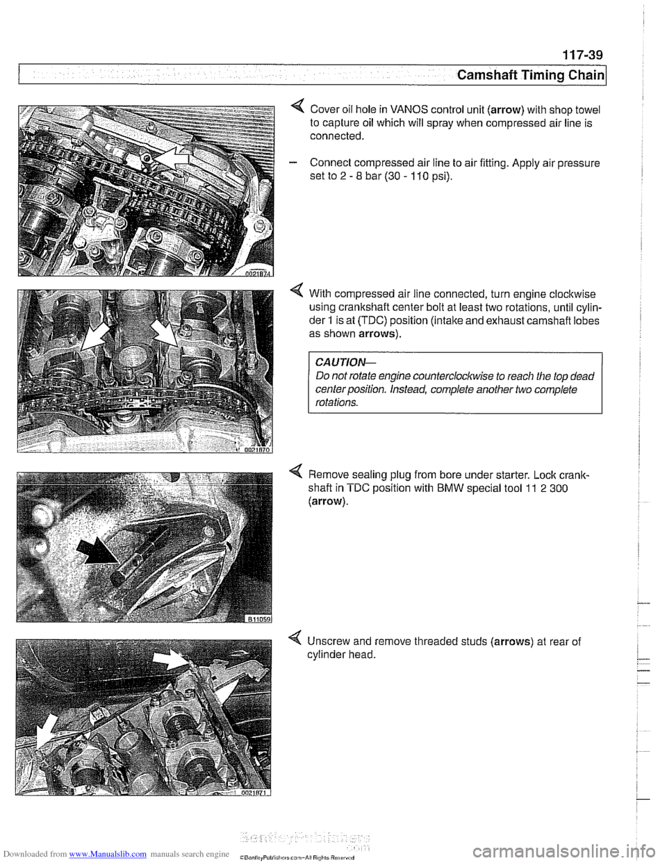
4 Cover oil hole in VANOS control unit (arrow) with shop towel
to capture oil which will spray when compressed air line is
connected.
- Connect compressed air line to air fitting. Apply air pressure
set to
2 - 8 bar (30 - 110 psi).
4 With compressed air line connected, turn engine clocltwise
using crankshaft center bolt at least two rotations, until cylin-
der
1 is at (TDC) position (intake and exhaust carnshafl lobes
as shown arrows).
Do not rotate engine
countercloclwise to reach the top dead
centerposition. Instead, complete another two complete
Remove sealing plug from bore under starter. Lock
crank-
shafl in TDC position with BMW special tool 11 2 300
(arrow).
-
4 Unscrew and remove threaded studs (arrows) at rear of
cylinder head.
Page 287 of 1002
Downloaded from www.Manualslib.com manuals search engine
... -.
Camshaft Timing chain1
Timing chains, removing
(M52 TU and M54 engines)
Camshaft timing chain removal requires that the oil pan be re-
moved. See
119 Lubrication System. Also required is re-
moval of the VANOS control
unit and disassembly of the
intake and exhaust camshaft sprocket assemblies as de-
scribed earlier in this repair group.
Special BMW
service tools are needed for timing chain re-
moval and installation. The special tools assure proper timing
of the valvetrain. Precise
marlts to set the timing on the cam:
shafts are not provided for reassembly. Read the procedures
through before beginning the job.
CA
UTION-
If the camshafts are not properly timed, the pistons can con-
tact the valves.
- D~sconnect negative (-) cable from battery.
CAUTION-
* Disconnecting the battery may erase fault code@) stored in
control module memory. Check for fault codes using spe-
cial
BMW diagnostic equipment.
Prior to disconnecting the battery, read the battery dis-
connection
cautfons given in 001 General Cautions
and
Warninqs.
- Remove VANOS control unit. See VANOS control unit, re-
moving
(M52 TU and M54 engines).
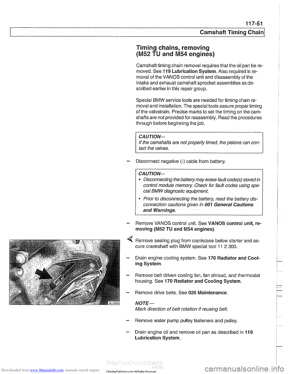
Remove sealing plug from crankcase below starter and se-
cure crankshaft with
BMW special tool ll 2 300.
Drain engine cooling system. See 170 Radiator and Cool-
ing System.
Remove belt driven cooling fan, fan shroud, and thermostat
housing. See
170 Radiator and Cooling System.
Remove drive belts. See
020 Maintenance.
NOTE-
Mark direction of belt rotation if reusing belt.
- Remove water pump pulley fasteners and pulley.
- Drain engine oil and remove oil pan as described in 119
Lubrication System.
Page 306 of 1002
Downloaded from www.Manualslib.com manuals search engine
I Camshaft Timins Chain
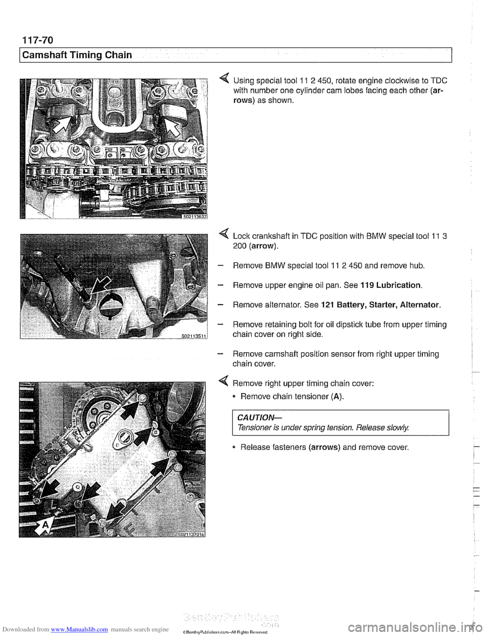
4 Using special tool 11 2 450, rotate engine clocltwise to TDC
with number one cylinder cam lobes facing each other (ar-
rows)
as shown.
4 Lock crankshaft in TDC position with BMW special tool 11 3
200 (arrow).
- Remove BMW special tool 11 2 450 and remove hub.
- Remove upper engine oil pan. See 119 Lubrication.
- Remove alternator. See 121 Battery, Starter, Alternator.
- Remove retaining bolt for oil dipstick tube from upper timing
chain cover on right side.
- Remove camshaft position sensor from right upper timing
chain cover.
< Remove right upper timing chain cover:
Remove chain tensioner
(A).
CAUTIOG
Tensioner is under spring tension. Release slowly. 1
Release fasteners (arrows) and remove cover