height adjustment BMW 525i 2000 E39 Workshop Manual
[x] Cancel search | Manufacturer: BMW, Model Year: 2000, Model line: 525i, Model: BMW 525i 2000 E39Pages: 1002
Page 649 of 1002
Downloaded from www.Manualslib.com manuals search engine
Front Suspension
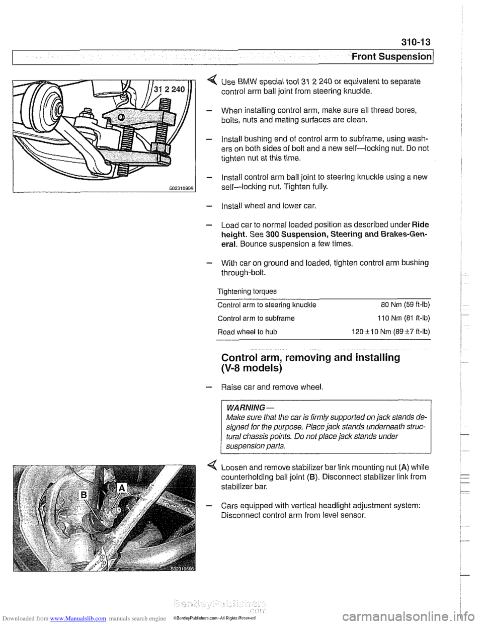
< Use BMW special tool 31 2 240 or equivalent to separate
control arm ball joint from steering ltnuckle.
- When installing control arm, make sure all thread bores.
bolts, nuts and mating surfaces are clean.
- Install bushing end of control arm to subframe, using wash-
ers on both sides of bolt and a new self-locking nut. Do not
tighten nut at this time.
- Install control arm ball joint to steering lknucltle using a new
self-locking nut. Tighten fully.
- Install wheel and lower car.
- Load car to normal loaded position as described under Ride
height. See
300 Suspension, Steering and Brakes-Gen-
eral. Bounce suspension a few times.
- With car on ground and loaded, tighten control arm bushing
through-bolt.
Tightening torques
Control arm to steering ltnuckle
80 Nm (59 ft-lb)
Control arm to subframe 110 Nm (81 It-lb)
Road wheel to hub 120ilO Nm (8957 it-lb)
Control arm, removing and installing
(V-8 models)
- Raise car and remove wheel
WARNING-
Make sure that the car is firmly supported on jack stands de-
signed for the purpose. Place jack stands underneath struc-
tural
cliassis points. Do not place jack stands under
suspension parts.
Loosen and remove stabilizer bar link mounting nut
(A) while
counterholding ball joint
(B). Disconnect stabilizer link from
stabilizer bar.
- Cars equipped with vertical headlight adjustment system:
Disconnect control arm from level sensor.
Page 710 of 1002
Downloaded from www.Manualslib.com manuals search engine
[Rear Suspension Swing arm, removing and installing
(sedan models)
CAUTION-
If working on a vehicle with compressed airshock absorbers,
disable air supply pump by disconnecting electrical plug be-
fore performing any repairs.
- Raise rear end of car and remove wheel
WARNING-
Make sure the car is firmly supported on jack stands de-
signed for the purpose. Place jack stands underneath struc-
tural chassis points. Do not place jack stands under
sus~ension Darts.
- Disconnect control rod for ride height sensor if applicable.
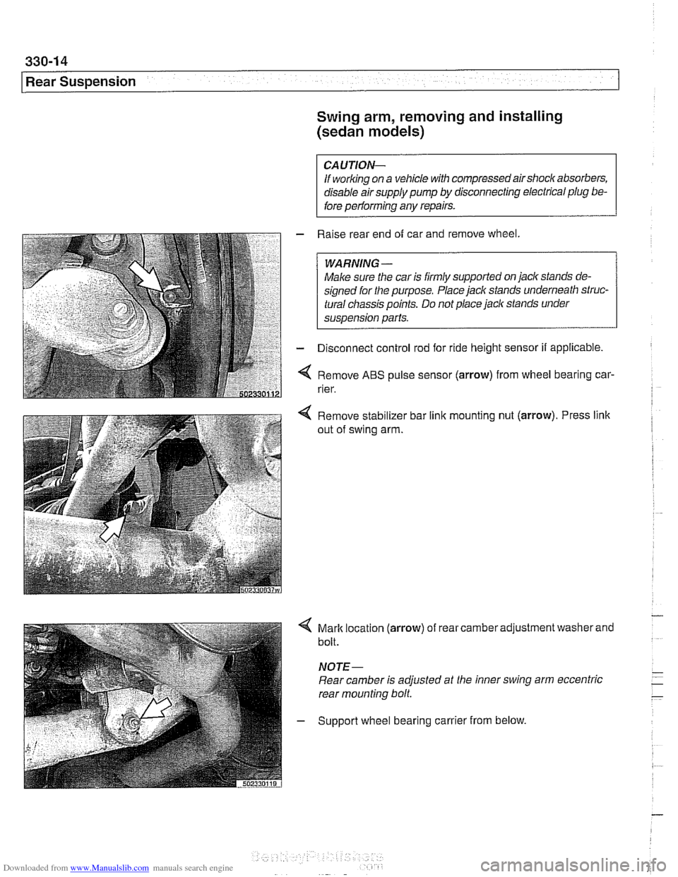
Remove
ABS pulse sensor (arrow) from wheel bearing car-
rier.
Remove stabilizer bar link mounting nut
(arrow). Press link
out of swing arm.
4 Mark location (arrow) of rear camber adjustment washer and
bolt.
NOTE-
Rear camber is adjusted at the inner swing arm eccentric
rear mounting bolt
- Support wheel bearing carrier from below.
Page 713 of 1002
Downloaded from www.Manualslib.com manuals search engine
Rear ~us~ensionl
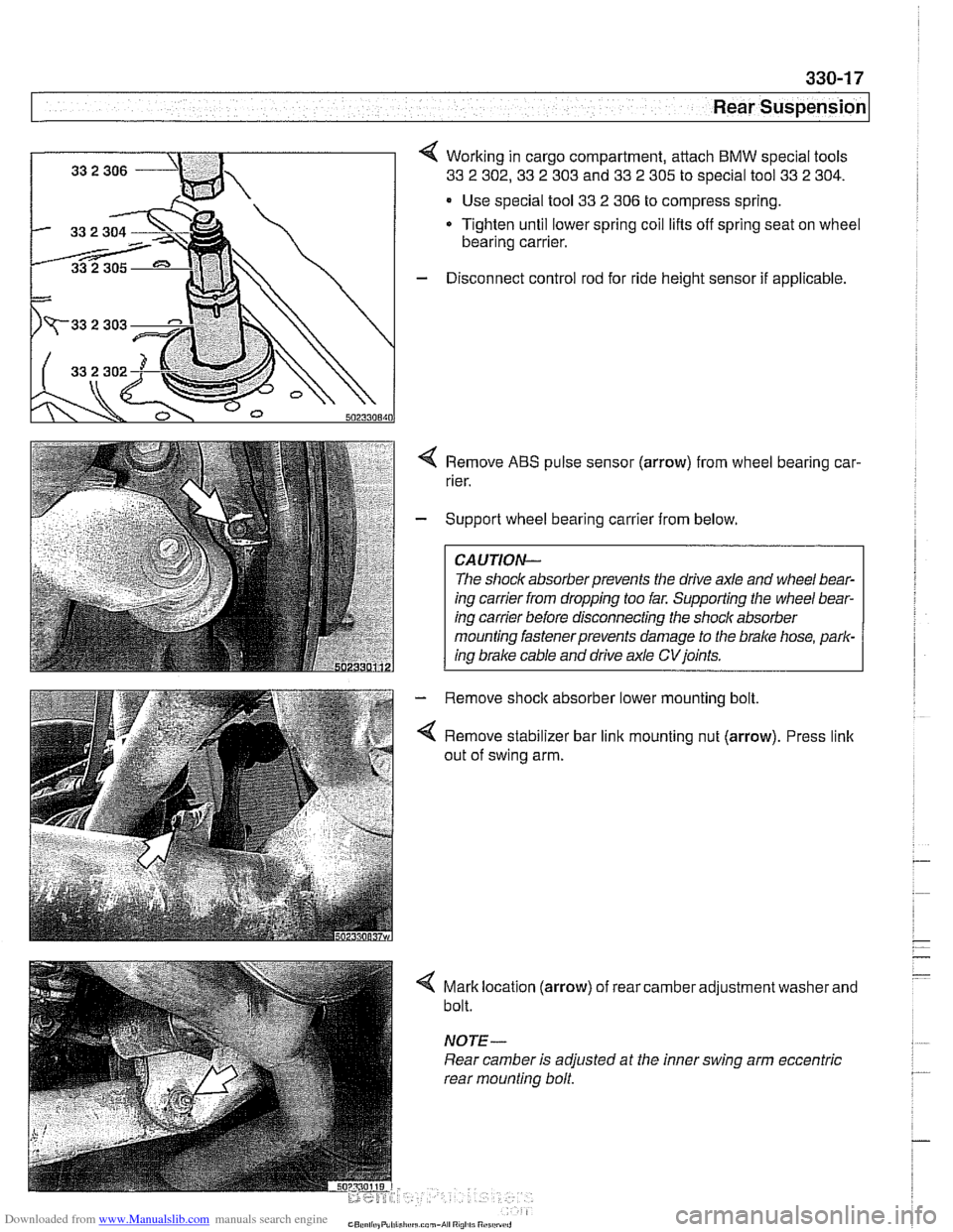
Working in cargo compartment, attach BMW special tools
33 2 302,33 2 303 and 33 2 305 to special tool 33 2 304.
Use special tool 33 2 306 to compress spring.
Tighten until lower spring coil lifts off spring seat on wheel
bearing carrier.
- Disconnect control rod for ride height sensor if applicable.
4 Remove ABS pulse sensor (arrow) from wheel bearing car-
rier.
- Support wheel bearing carrier from below.
CAUTION-
The shock absorberprevents the drive axle and wheel bear-
ing carrier from dropping too far. Supporting the wheel bear-
ing carrier before disconnecting the shock absorber
mounting fastenerprevents damage to the
brake hose, park-
ing brake cable and drive axle
CVjoints.
- Remove shock absorber lower mounting bolt
4 Remove stabilizer bar link mounting nut (arrow). Press link
out of swing arm.
4 Mark location (arrow) of rear camber adjustment washer and
bolt.
NOTE -
Rear camber is adjusted at the inner swing arm eccentric
rear mounting bolt.
Page 814 of 1002
Downloaded from www.Manualslib.com manuals search engine
41 0-8
(Fenders, Engine Hood
Hood, aligning
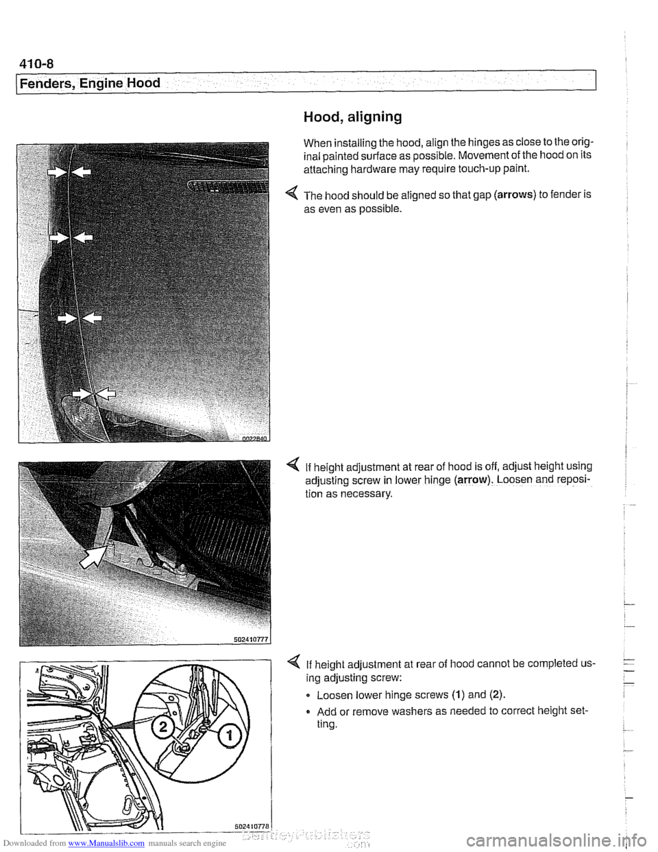
When installing the hood, align the hinges as close to the orig-
inal painted surface as possible. Movement of the hood on its
attaching hardware may require touch-up paint.
The hood should be aligned so that gap
(arrows) to fender is
as even as possible.
4 If height adjustment at rear of hood is off, adjust height using
adjusting screw in lower hinge
(arrow). Loosen and reposi-
tion as necessary.
If height adjustment at
ing adjusting screw: rear
of
hood cannot be completed us-
Q Loosen lower hinge screws (1) and (2).
Add or remove washers as needed to correct height set-
ting.
Page 841 of 1002
Downloaded from www.Manualslib.com manuals search engine
Trunk Lid, Tailgate
Rear window and tailgate, alignment
- Alignment procedures involve adjusting tailgate, window, and
spoiler to have equal space between
iefl and right sides and
to be flush with body. Measurement locations and specific di-
mensions are shown.
- If alignment has been disturbed during repair, adjust fit of tail-
gate to body. Then adjust fit of rear window to tailgate.
Clearance of the rear window is adjusted by adding or re-
moving shims between hinge bracket and rear window
(maximum of three shims).
Adjust spoiler gap to body last.
Height of spoiler is set by alignment of the rear tailgate.
Gap of spoiler to body is set by adjusting spoiler attach-
ment fasteners.
- Lateral and vertical alignment of the window and tailgate is
done using hinge bolts. Fine adjustment of the tailgate to the
body is made using rubber stop buffers and latch assembly.
Spoiler gap specification Rear spoiler to roof 4.25
- 5 mm
(0.167 - 0.197 in)
Max. deviation from parallel 0.5
mm (0.019 in)
Tailgate alignment, preliminary work
- Open rear window and tailgate.
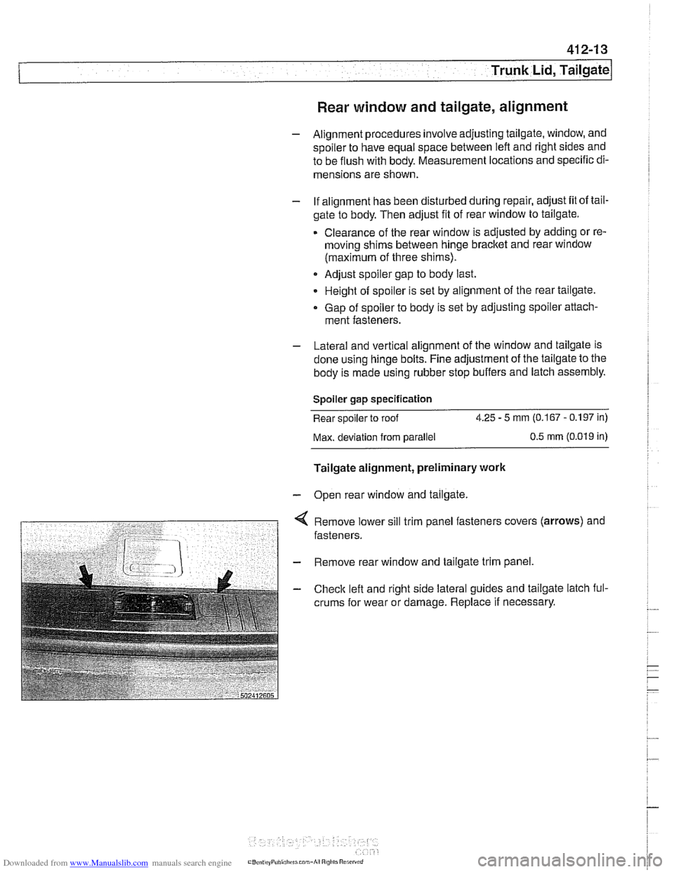
< Remove lower sill trim panel fasteners covers (arrows) and
fasteners.
- Remove rear window and tailgate trim panel.
- Checlc left and right side lateral guides and tailgate latch ful-
crums for wear or damage. Replace
if necessary.
Page 843 of 1002
Downloaded from www.Manualslib.com manuals search engine
Trunk Lid, ~ail~atel
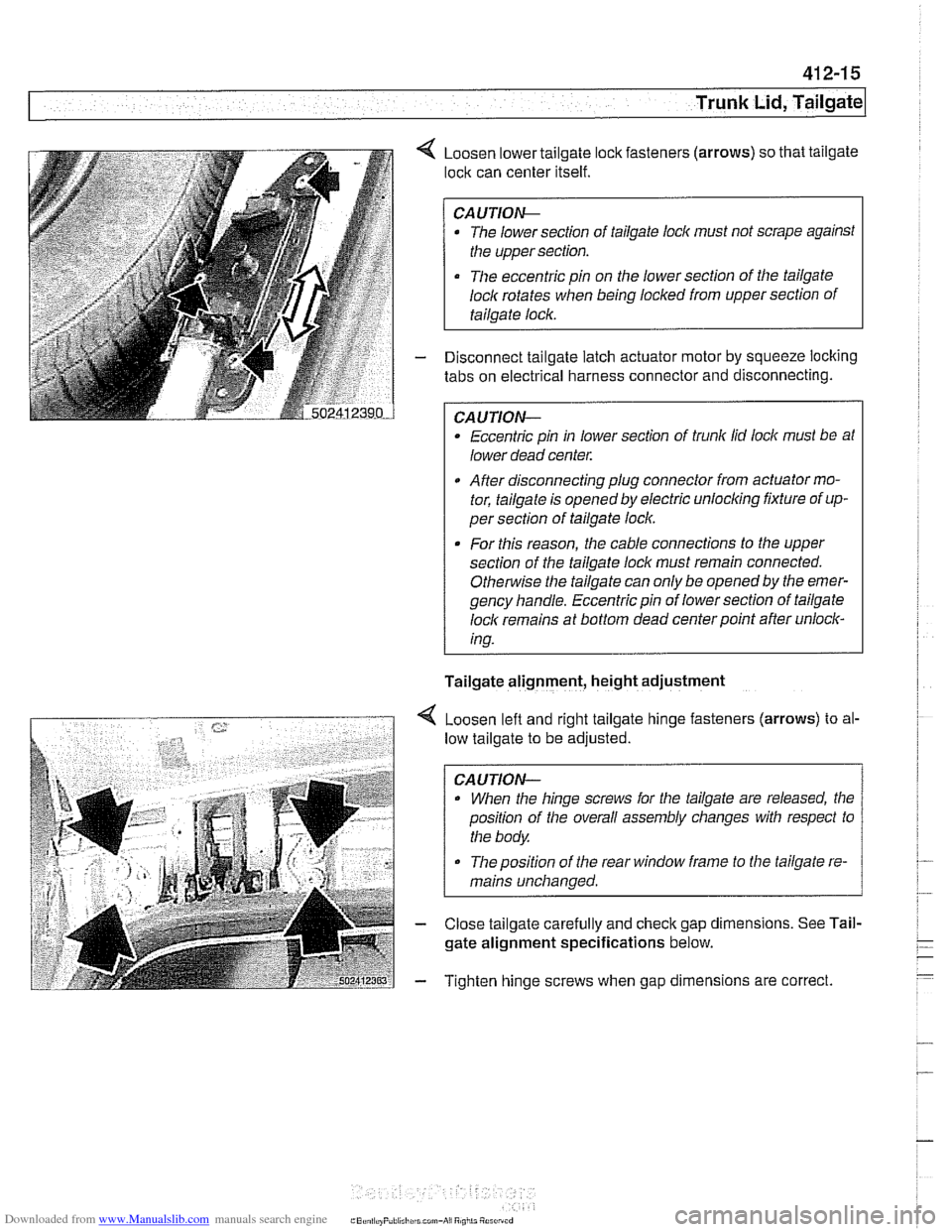
4 Loosen lower tailgate lock fasteners (arrows) so that tailgate
lock can center itself.
CAUTION-
The lower section of tailgate lock must not scrape against
the upper section.
The eccentric pin on the lower section of the tailgate
loclc rotates
when being locked from upper section of
tailgate lock.
- Disconnect tailgate latch actuator motor by squeeze locking
tabs on electrical harness connector and disconnecting.
CAUTION-
Eccentric pin in lower section of trunk lid lock must be at
lower dead center.
After disconnecting plug connector from actuator mo-
tor, tailgate is opened by electric
unloclcing fixture of up-
per section of tailgate loclc.
. For this reason, the cable connections to the upper
section of the tailgate loclc must remain connected.
Othe~tise the tailgate can only be opened by the emer-
gency handle. Eccentric pin of lower section of tailgate
loclc remains at bottom dead center point after unlock-
ing.
Tailgate alignment, height adjustment
4 Loosen left and right tailgate hinge fasteners (arrows) to al-
low tailgate to be adjusted.
CAUTION-
. When the hinge screws for the tailgate are released, the
position of the overall assembly changes with respect to
the body.
The position of the rear window frame to the tailgate re-
mains unchanged.
- Close tailgate carefully and check gap dimensions. See Tail-
gate alignment specifications below.
- Tighten hinge screws when gap dimensions are correct.
Page 845 of 1002
![BMW 525i 2000 E39 Workshop Manual Downloaded from www.Manualslib.com manuals search engine
. -
Trunk Lid, ~ail~ate]
< Adjustment D:
a = 4.5 rnrn + ll- 0.5 rnrn (0.18 in + 0.041- 0.02 in)
b = 3.7 rnrn +2 l- 1 rnrn (0.1 5 in + 0 BMW 525i 2000 E39 Workshop Manual Downloaded from www.Manualslib.com manuals search engine
. -
Trunk Lid, ~ail~ate]
< Adjustment D:
a = 4.5 rnrn + ll- 0.5 rnrn (0.18 in + 0.041- 0.02 in)
b = 3.7 rnrn +2 l- 1 rnrn (0.1 5 in + 0](/img/1/2822/w960_2822-844.png)
Downloaded from www.Manualslib.com manuals search engine
. -
Trunk Lid, ~ail~ate]
< Adjustment D:
a = 4.5 rnrn + ll- 0.5 rnrn (0.18 in + 0.041- 0.02 in)
b = 3.7 rnrn +2 l- 1 rnrn (0.1 5 in + 0.081 - 0.04 in)
4 Adjustment E:
1 tailgate lid
a=1.3rnrnil rnrn(0.05ini0.04in)
2 rear side panel
b = 4.5 rnrn + 11 - 0.5 rnrn (0.1 8 in + 0.041 - 0.02 in)
4 Adjustment F:
a = 1.3 rnrn 21 rnrn (0.05 in 20.04 in)
b = 1 rnrn 20.5 rnrn (0.04 i0.02 in)
* c=1.3rnrn+lrnrn/-1.3rnrn(0.05in+0.04in-0.05in)
d = 4.5 rnrn + 1 rnrn I - 0.5 rnrn (0.18 in + 0.041 - 0.02 in)
CAUTION-
Rear window frame must not extend above height of roof.
Olherwise, wind noise will be created.
Page 848 of 1002
Downloaded from www.Manualslib.com manuals search engine
Trunk Lid, Tailgate
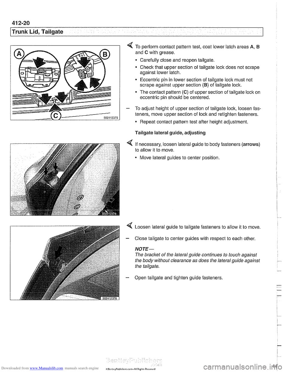
4 To periorm contact pattern test, coat lower latch areas A, 6
and C with grease.
Carefully close and reopen tailgate.
Check that upper section of tailgate lock does not scrape
against lower latch.
* Eccentric pin in lower section of tailgate loclc must not
scrape against upper section
(B) of tailgate lock.
The contact pattern (C) of upper section of tailgate lock on
eccentric pin should be centered.
- To adjust height of upper section of tailgate lock, loosen fas-
teners, move upper section of lock and retighten fasteners.
Repeat contact pattern test after height adjustment.
Tailgate lateral guide, adjusting
< If necessary, loosen lateral guide to body fasteners (arrows)
to allow it to move.
Move lateral guides to center position.
< Loosen lateral guide to tailgate fasteners to allow it to move.
- Close tailgate to center guides with respect to each other.
NOTE-
The bracket of the lateral guide continues to touch against
the body without clearance as does the lateral guide against
the tailgate.
- Open tailgate and tighten guide fasteners.
Page 849 of 1002
Downloaded from www.Manualslib.com manuals search engine
41 2-21
Trunk Lid, ~ailaatel
Rear window, adjusting
NOTE- Three versions of rear window are used on
Sport Wagon
models.
Tailgate must be correctly adjusted before rear window ad-
justments are made.
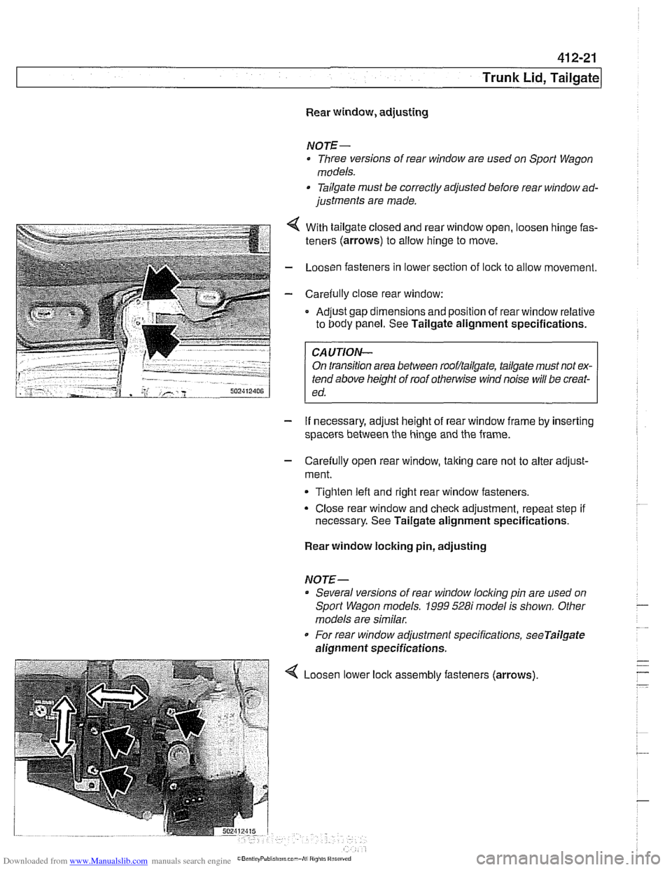
- . . . . . .. .. 4 With tailgate closeo ano rear window open, oosen ninge fas-
teners (arrows) to allow ninge to move.
- LoosL'n fasteners n lower section of ock to al ow movement.
- Care& ly c ose rear window:
Ad.~st gap dmensions and poston of rear window relative
to Oody panel. See Tailgate alignment specifications. .
FA-UTION- I
On transition area between rooflailgate, tailgate must not ex-
tend above height of roof
othe~lise wind noise will be creat-
ed.
- If necessary, adjust height of rear window frame by inserting
spacers between the hinge and the frame.
- Carefully open rear window, taking care not to alter adjust-
ment.
Tighten left and right rear window fasteners.
Close rear window and check adjustment, repeat step if
necessary. See Tailgate alignment specifications.
Rear window locking pin, adjusting
NOTE-- Several versions of rear window
locldng pin are used on
Sport Wagon models.
1999 528i model is shown. Other
models are similar.
For rear window adjustment specifications,
seeTailgate
alignment specifications.
Loosen lower assembly fasteners (arrows)
Page 862 of 1002
Downloaded from www.Manualslib.com manuals search engine
I Exterior Trim, Bumpers
Tightening torques Impact absorber to chassis
(M8 nut) 20 Nm (15 ft-lb)
Impact absorber to chassis
(M6 nut) 9 Nm (80 In-lb
Bumper bracket to impact absorber 45 Nm (32 ft-lb)
(MI0 bolt)
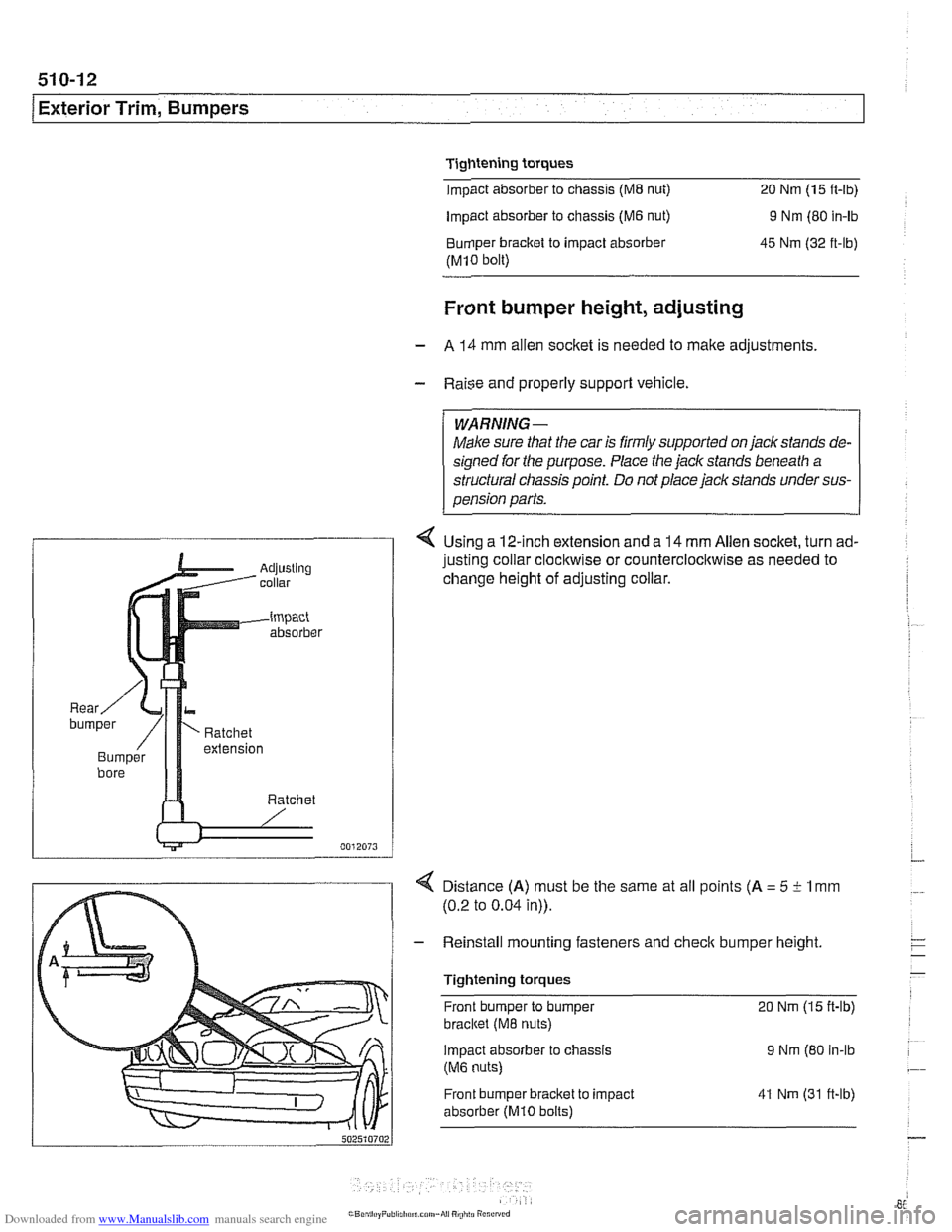
Front bumper height, adjusting
- A 14 mm allen socket is needed to make adjustments
- Raise and properly support vehicle.
WARNING-
Make sure that the car is firmly supported on jackstands de-
signed for the purpose. Place the jack stands beneath a
structural chassis point.
Do not place jack stands under sus-
pension parts.
4 Using a 12-inch extension and a 14 mm Allen socket, turn ad-
justing collar
clocl~wise or counterclocl~wise as needed to
change height of adjusting collar.
4 Distance (A) must be the same at all points (A = 5 i- 1 mm
(0.2 to 0.04 in)).
- Reinstall mounting fasteners and check bumper height
Tightening torques Front bumper to bumper
20 Nm (15 ft-lb)
bracltet (M8 nuts)
Impact absorber
to chassis 9 Nm (80 in-lb
(M6 nuts)
Front bumper bracket to impact
absorber
(MI0 bolts)
41 Nm (31 ft-lb)