Brake light BMW 525i 2001 E39 User Guide
[x] Cancel search | Manufacturer: BMW, Model Year: 2001, Model line: 525i, Model: BMW 525i 2001 E39Pages: 1002
Page 728 of 1002
Downloaded from www.Manualslib.com manuals search engine
I Rear Suspension
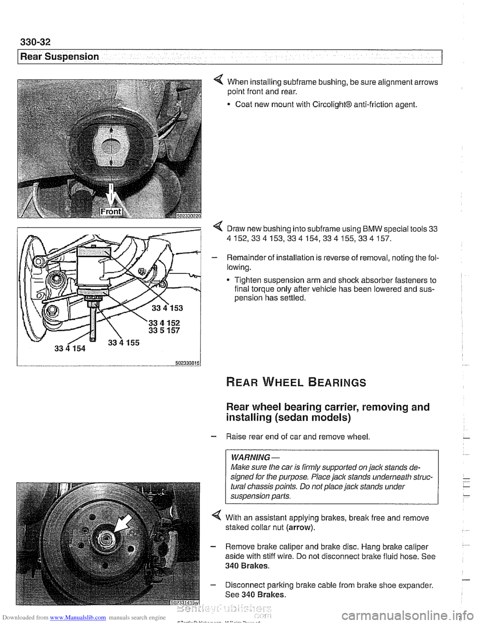
4 When installing subframe bushing, be sure alignment arrows
point front and rear.
Coat new mount with
CircolightB anti-friction agent.
< Draw new bushing into subframe using BMW special tools 33
4152,334153,334154,334155,334157.
- Remainder of installation is reverse of removal, noting the fol-
lowing.
* Tighten suspension arm and shock absorber fasteners to
final torque only after vehicle has been lowered and
sus-
oension has settled.
Rear wheel bearing carrier, removing and
installing (sedan models)
- Raise rear end of car and remove wheel
WARNING-
Make sure the car is firmly supported on jaclc stands de-
signed for the purpose. Place
jaclc stands underneath struc-
tural chassis points. Do not place jaclc stands under
suspension parts.
4 With an assistant applying brakes, break free and remove
staked collar nut (arrow).
- Remove brake caliper and brake disc. Hang brake caliper
aside with stiff wire. Do not disconnect brake fluid hose. See
340 Brakes.
- Disconnect parking brake cable from brake shoe expander.
See 340 Brakes.
Page 759 of 1002
Downloaded from www.Manualslib.com manuals search engine
Final ~rivel
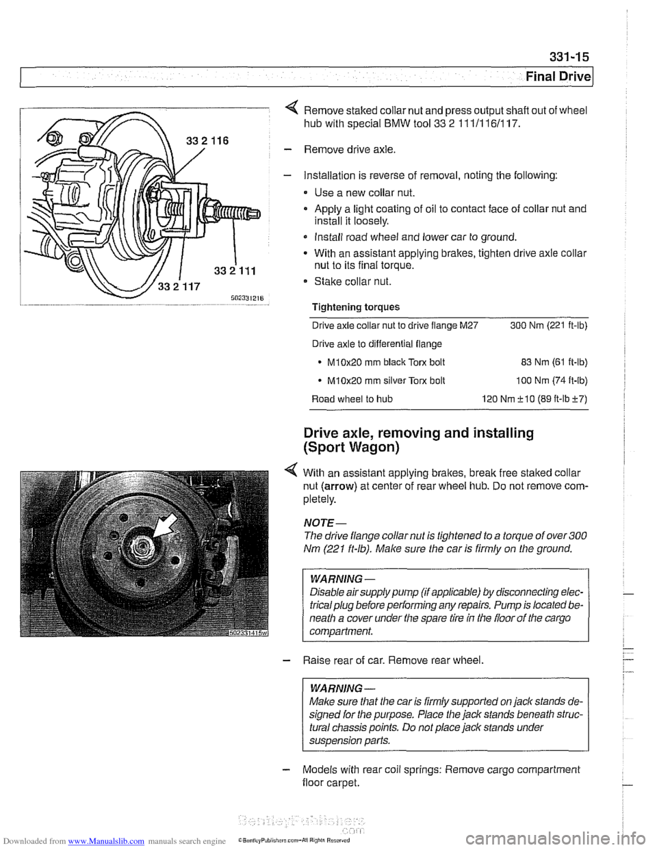
4 Remove staked collar nut and press output shafl out of wheel
hub with special
BMW tool 33 2 111/116/117.
- Remove drive axle.
- Installation is reverse of removal, noting the following:
Use a new collar nut.
a Apply a light coating of oil to contact face of collar nut and
install it loosely.
* Install road wheel and lower car to ground.
- With an assistant applying brakes, tighten drive axle collar
nut to its final torque.
Stake collar nut.
Tightening torques
-
Drive axle collar nut to drive flange M27 300 Nrn (221 ft-lb)
Drive axle to differential flange
* M10x20 rnm black Torx bolt
83 Nrn (61 ft-lb)
M10x20 rnrn silver Torx bolt
100 Nrn (74 ft-lb)
Road wheel to hub 120 Nrn f 10 (89 ft-lbf7)
Drive axle, removing and installing
(Sport Wagon)
4 With an assistant applying brakes, brealc free staked collar
nut (arrow) at center of rear wheel hub. Do not remove com-
pletely.
NOJE-
The drive flange collar nut is tightened to a torque of over 300
Nm (221 ft-lb). Make sure the car is firmly on the ground.
WARNING -
Disable airsupply pump (if applicable) by disconnecting elec-
tricalplug before performing any repairs. Pump is located be-
neath a cover under the spare tire
in the floor of the cargo
compartment.
- Raise rear of car. Remove rear wheel.
WARNING -
Malce sure that the car is firmly supported on jack stands de-
signed for the purpose. Place the jack stands beneath struc-
tural chassis points. Do not place jack stands under
suspension parts.
- Models with rear coil springs: Remove cargo compartment
floor carpet.
Page 761 of 1002
Downloaded from www.Manualslib.com manuals search engine
331-17
Final ~rivel
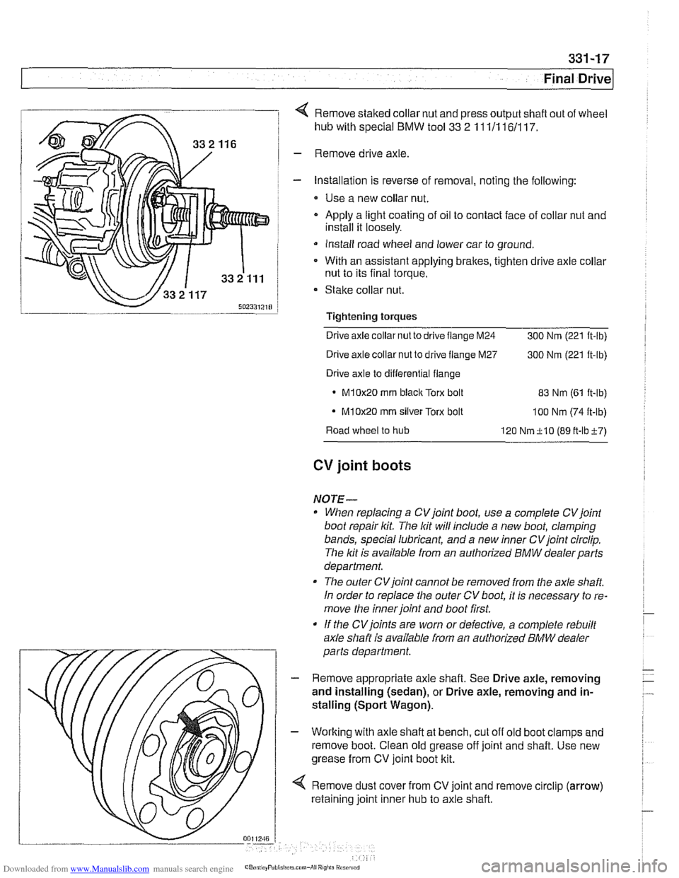
4 Remove staked collar nut and press output shaft out of wheel
hub with special
BMW tool 33 2 11 111 161117.
- Remove drive axle
- Installation is reverse of removal, noting the following:
* Use a new collar nut.
- Apply a light coating of oil to contact face of collar nut and
install it loosely.
Install road wheel and lower car to ground.
* With an assistant applying brakes, tighten drive axle collar
nut to its final torque.
Stake collar nut.
Tightening
torques
Drive axle collar nut to drive flange M24
300 Nrn (221 ft-lb)
Drive axle collar nut to drive flange M27
300 Nrn (221 ft-lb)
Drive axle to differential flange
M10x20 rnrn blaclc Torx bolt 83 Nrn (61 it-lb)
- M10x20 rnrn silver Torx bolt loo Nrn (74 ft-lb)
Road wheel to hub
120 Nrn+lO (89tt-lbi-7)
CV joint boots
NOTE-
When replacing a CVjoint boot, use a complete CVjoint
boot repair kit. The lit will include a new boot, clamping
bands, special lubricant, and a new inner CV joint circlip.
The lit is available from an authorized
BMW dealerparts
department.
The outer CVjoint cannot be removed from the axle
shaft
In order to replace the outer CV boot, it is necessary to re-
move the inner joint and boot first.
If the
CVjoints are worn or defective, a complete rebuilt
axle shaft is available from an authorized
BMW dealer
parts department.
- Remove appropriate axle shaft. See Drive axle, removing
and installing (sedan), or Drive axle, removing and in-
stalling (Sport Wagon).
- Working with axle shaft at bench, cut off old boot clamps and
remove boot. Clean old grease off joint and shaft. Use new
grease from CV joint boot kit.
4 Remove dust cover from CV joint and remove circlip (arrow)
retaining joint inner hub to axle shaft.
Page 768 of 1002
Downloaded from www.Manualslib.com manuals search engine
340-6
1 Brakes
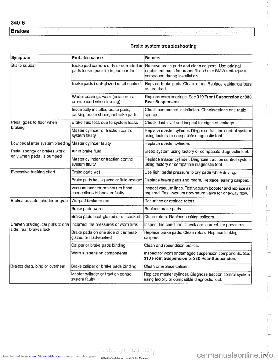
Brake system troubleshooting
/symptom I Probable cause 1 Repairs
Brake squeal
Pedal goes to floor when
bralting
Low pedal after system bleeding
Pedal spongy or brakes work
only when pedal is pumped
Excessive braking effort
Brakes pulsate, chatter or grab
Uneven
bralting, car pulls to one
side, rear braltes
loclt
Brakes drag, bind or overheat Brake
pad carriers dirty or corroded or
pads loose (poor fit) in pad carrier
Braite pads heat-glazed or oil-soaked
Wheel bearings worn (noise most
pronounced when turning)
Incorrectly Installed brake pads,
parking bralte shoes, or bralte parts
Brake fluid loss due to system leaks
Master cylinder or traction control
system faulty
Master cylinder faulty
Air in braite fluid
Master cylinder or traction control
system faulty
Brake pads wet
Brake pads
heat-glazedorfluid-soalted
Vacuum booster or vacuum hose
connections to booster faulty
--- Warped brake rotors
Brake pads worn
Brake pads heat-glazed or oil-soaked Remove
brake pads and clean calipers. Use original
equipment pads for proper fit and use BMW anti-squeal
compound during installation,
Replace brake pads. Ciean rotors. Replace leaking caliper:
as required.
Replace worn bearings. See 310 Front Suspension
or33C
Rear Suspension.
Check component installation. Checldreplace anti-rattle
springs.
Checlt fluid level and inspect for signs of leakage.
Replace master cylinder. Diagnose traction control system
using factory or compatible diagnostic tool.
Replace master cylinder.
Bleed system using factory or compatible diagnostic tool.
Replace master cylinder. Diagnose traction control system
using factory or compatible diagnostic tool.
Use light pedal pressure to dry pads while driving.
Replace
bralte pads and rotors. Replace leaking calipers.
lnspect vacuum lines. Test vacuum booster and replace as
required. Test vacuum non-return valve for one-way flow.
Resurface or replace rotors.
Replace brake pads.
Clean rotors. Replace leaiting calipers.
Incorrect tire pressures or worn tires
Brake pads on one side of car heat-
glazed or fluid-soaked
Caliper or brake pads binding
Worn suspension components
Brake caliper or brake pads binding
Master cylinder or traction control
system faulty lnspect
tire condition. Checlt and correct tire pressures.
Replace brake pads. Clean rotors. Replace leaking
calipers.
Clean and recondition brakes.
Inspect for worn or damaged suspension components. See
310 Front Suspension or 330 Rear Suspension.
Ciean or replace caliper.
Replace master cylinder. Diagnose traction control system
using faclory or compatible diagnostic tool.
Page 776 of 1002
Downloaded from www.Manualslib.com manuals search engine
340-1 4
Brakes
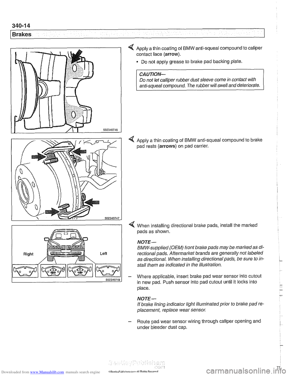
4 Apply a thin coating of BMW anti-squeal compound to caliper
contact face
(arrow).
Do not apply grease to brake pad backing plate.
Right Left
CAUTION-
Do not let calliper rubber dust sleeve come in contact with
anti-squeal compound. The rubber will swell and deteriorate.
4 Apply a thin coating of BMW anti-squeal compound to bralte
pad rests (arrows) on pad carrier.
4 When installing directional brake pads, install the marked
pads as shown.
NOTE-
BMW-supplied (OEM) front brake pads may be marked as di-
rectionalpads. Aftermarket brands are generally not labeled
as directional. When installing directional pads, be sure to in-
stall them as indicated in the illustration.
- Where applicable, insert brake pad wear sensor into cutout
in new pad. Push sensor into pad cutout until it locks into
place.
- -
- NOTE-
If brake lining indicator light illuminatedprior to brake pad re-
placement, replace wear sensor.
- Route pad wear sensor wiring through caliper opening and
under bleeder dust cap.
Page 777 of 1002
Downloaded from www.Manualslib.com manuals search engine
340-1 5
Brakes
- Remainder of installation is reverse of removal.
- Clean brake caliper mounting bolts (7 mm Allen). Replace
ones which are not in perfect condition. Do not grease.
Top up brake fluid to MAX marking.
- Before driving car, pump bralte pedal several times so that
brake pads contact brake rotors.
Check that brake fluid level is correct. Top up if necessary.
Hold ignition key for at least
30 seconds in accessory po-
sition without starting engine. This clears any fault codes in
memory and turns off brake pad warning light.
Tightening torques Brake caliper to pad carrier
(7 mm Allen)
Front caliper
30 Nm (22 It-lb)
- Rear caliper 28 Nm (21 It-lb)
Road wheel to hub
120i 10 Nm (89i7 ft-lb)
Brake rotors, removing and installing
- Raise car and remove wheels
WARNING-
Male sure that the car is firmly supported on jack stands de-
signed for the purpose. Place jack stands beneath structural
chassis points. Do not place jack stands under suspension
parts.
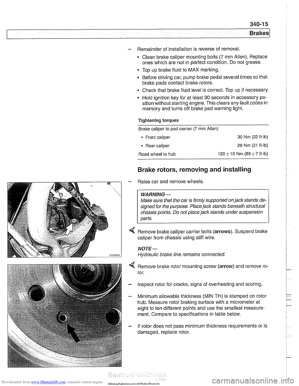
Remove brake caliper carrier bolts (arrows). Suspend brake
caliper from chassis using stiff wire.
NOTE-
Hydraulic brake line remains connected.
4 Remove bralte rotor mounting screw (arrow) and remove ro-
tor.
- Inspect rotor for cracks, signs of overheating and scoring.
- Minimum allowable thickness (MIN TH) is stamped on rotor
hub. Measure rotor braking surface with a micrometer at
eight to ten different points and use the smallest measure-
ment. Compare to specifications in table below.
- If rotor does not pass minimum thickness requirements or is
damaged, replace rotor.
Page 785 of 1002
Downloaded from www.Manualslib.com manuals search engine
340-23
Brakes
- Using flat-bladed screwdriver, reach into brake drum through
lug bolt hole. Turn brake adjuster until wheel no longer turns.
Back adjuster off
12 notches.
Parking brake adjusting (initial)
Back
off adjuster through wheel
lug bolt hole 12 notches
- Working inside car, set parking brake several times to seat
cable. Then pull parking brake
lever up two notches. Tighten
cable adjusting nuts until it is just possible to turn rear wheels
with slight resistance.
- Release lever and make sure rear wheels turn freely
- Turn on ignition. Pull up parlting brake lever 1 notch and
make sure that parking bralte warning light comes on. if not,
adjust parking bralte warning light contact switch.
- Install parking brake lever boot. Install road wheel lug bolts.
Tightening torque Road
wheel to hub 120 i. 10 Nrn (89 i- 7 ft-lb)
Parking brake shoes, removing and
installing
- Raise rear of car and remove road wheels.
WARNING-
Make sure that the car is firmly supported on jack stands de-
signed for
the purpose. Place jack stands beneath structural
chassis points. Do not place
jaclc stands under suspension
parts.
- Without disconnecting brake fluid hose, remove rear bralte
calipers from trailing arms. Remove rear brake rotors as de-
scribed earlier.
CAUTION-
Do not let the brake caliper assembly hang from the brake
hose. Support caliper from chassis with strong wire.
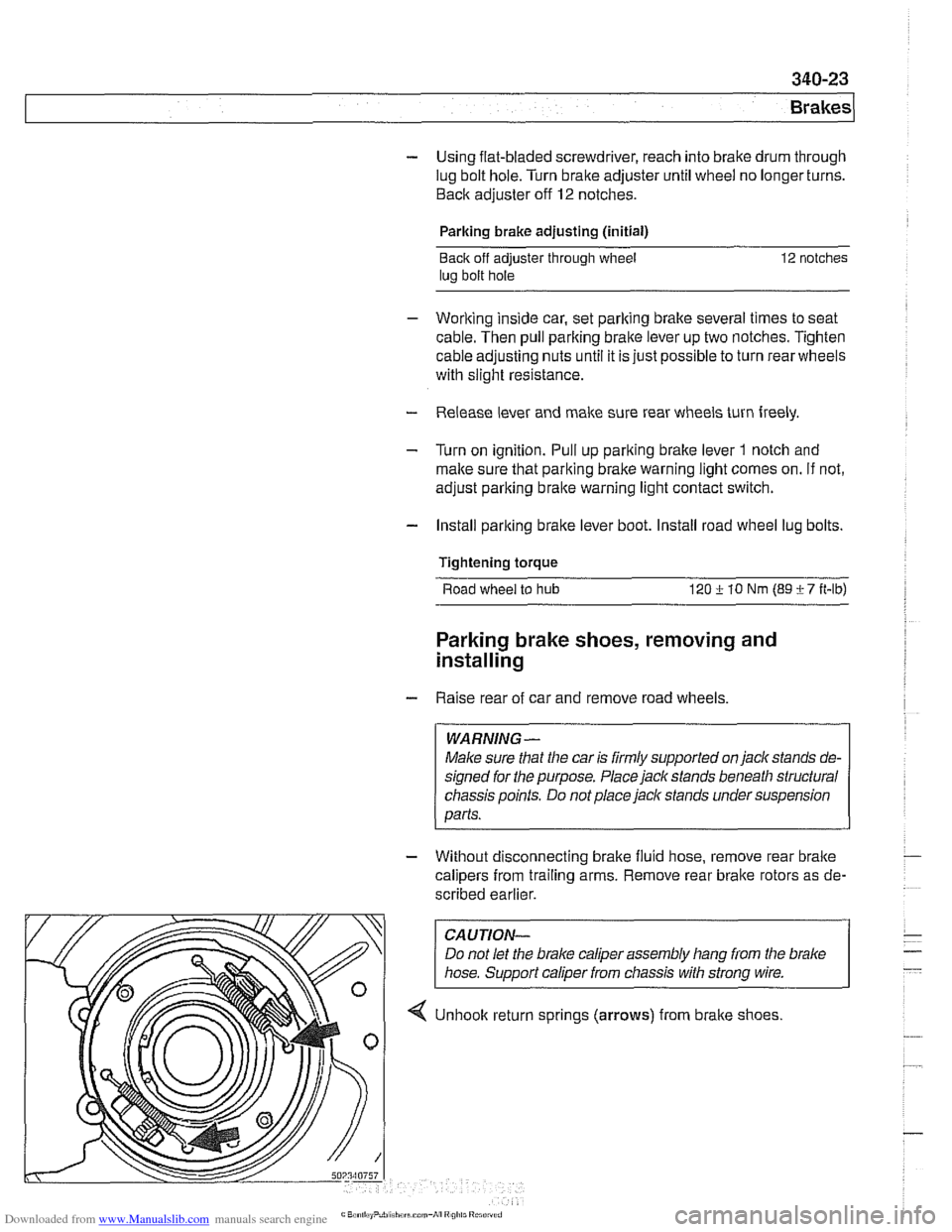
4 Unhook return sprlngs (arrows) from brake shoes
Page 792 of 1002
Downloaded from www.Manualslib.com manuals search engine
1 Brakes
- Remove precharge pump mounting bracket fasteners and re-
move pump.
- Installation is reverse of removal, noting the following:
Be sure to replace rubber pump mounts if damaged
01
worn.
Bleed brakes as described earlier.
Tightening torque Brake line
to precharge pump 18 Nrn (13 ft-lb)
DSC pressure sensor (1 999 - 2002 models)
On 1999 and later DSC systems, the DSC pressure sensor is
screwed into the DSC hydraulic unit (right rear of engine com-
partment).
WARNING-
* €39 cars require special BMW service equipment to prop-
erly bleed the brakes. Removal of the
DSCpressure sensor
is not recommended unless this equipment is available. For
safety reasons, the brake system on cars with ABS must be
bled using the procedures described in this repair group.
Switch off ignition and remove
key to male sure brake
system cannot be activated.
- Disconnect electrical harness connector at switch.
- Use BMW special tool 34 5 160 to remove and install sensor.
Inspect threads and sealing surfaces for damage.
* Work quicltly to avoid excessive brake fluid leakage.
Tightening torque
Pressure sensor
to hydraulic 19 Nrn (14ft-lb)
unit
- Reconnect harness connector
- Bleed front brakes as described earlier.
- Press on brakes and check for leaks at sensor.
- Turn on ignition and firmly depress brake pedal. Check that
DSC warning light does not come on.
Page 991 of 1002
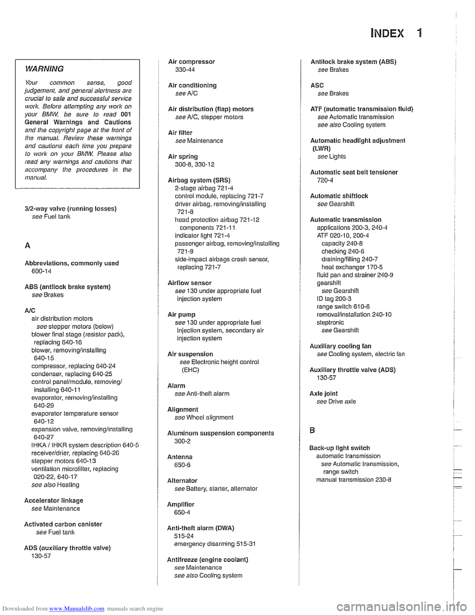
Downloaded from www.Manualslib.com manuals search engine
INDEX 'tl
WARNING
Your common sense, good
judgemenl, and general alertness are
crucial to sale and successiul service
worlr. Belore attempting any work on
your
BMM be sure lo read 001
General Warnings and Cautions
and the
copyriglll page at the front 01
the manual. Review these warnings
and
caulions each lime you prepare
lo work on your BMW. Please also
read any warnings and cautions that
accompany
tile procedures in the
manual.
312-way valve (running losses)
see Fuel tank
Abbreviations, commonly used 600-14
ABS (antilock brake system)
see
Bral(es
A/C air distribution motors
see stepper motors (below)
blower final stage (resistor pack),
replacing
640-16
blower, removinglinslalling
640-1 5
compressor, replacing
640-24 condenser, replacing 64045
control panellmodule, removing1
installing
640-1 1
evaporakr, removinglinstalling 640-29
evaporator temperature sensor
640-12 expansion valve, removinglinstailing
640-27
IHKA/ IHKR system description 640-5
receiveridrier, replacing 640-26
stepper motors 640-1 3 ventilation microiilter, replacing
020-22. 640-17
see also Heating
Accelerator
iinlcage
see Maintenance
Activated carbon canister
see Fuel tank
ADS (auxiliary throttle valve)
130-57
Air compressor
330-44
Air conditioning
see
AIC
Air distribution (flap) motors
seeNC, stepper motors
Air filter see Maintenance
Air spring
300-6, 330-12
Airbag system (SRS)
2-stage
airbag 721-4
control module, replacing 721-7 driver airbag, removinglinstalling
721-8
iiead protection airbag 721-12 components 721-1 1
indicator
lighl721-4
passenger airbag, removinglinstalling
721-9 side-impact airbags crash sensor,
replacing
721-7
Airflow sensor see 130 under appropriate
fuel
injection system
Air pump
see 130 under appropriate fuel
injection system, secondary air
injection system
Air suspension
see Electronic height control
(EHC)
Alarm
see Anti-theft alarm
Alignment see
Wheei alignment
Aluminum suspension components
300-2
Antenna 650-6
Alternator see Battery, starter, alte rnator
Amplifier
650-4
Anti-theft alarm (DWA)
515-24 emergency disarming 515-31
Antifreeze (engine coolant)
see Maintenance
see also Cooling system
Antilock brake system (ABS) see Brakes
ASC see Brakes
ATF (automatic transmission fluid)
see Automatic transmission
see also Cooling systern
Automatic headlight adjustmenl
(LWR) see Lights
Automatic seat belt tensioner
720-4
Automatic shiftloclc
see
Gearshift
Automatic transmission
applications
200-3, 240-4
ATF 020-10, 200-4
capacity 240-8 checking 240-6
drainingifilling 240-7
heat exchanger 170-5
fluid pan and strainer 240-9 gearshift
see Gearshift
ID tag
200-3 range switch 610-6
removaliinstallation 240-10
steptronic see Gearshift
Auxiliary cooling fan
see
Coollng system, electric Ian
Auxiliary throttle valve (ADS)
130-57
Axle joint
see Drive axle
Back-up light switch
automatic transmission see Automatic transmission. range switch
- .~.~~~
manual transmission 230-8 -
- I
Page 992 of 1002
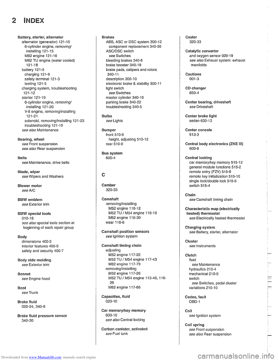
Downloaded from www.Manualslib.com manuals search engine
2 INDEX
Battery, starter, alternator
alternator (generator)
121-10
6-cylinder engine, removingi
installing 121-15
M62 engine 121-16
M62 TU engine (water cooled)
121-18
battery
121-5 charging 121-9
safety terminal 121-3
testing 121-5 charging system, troubleshooting
121-12
starter
121-1 9
6-cylinder engine, removingi instaliinq 121-20 . V-8 engine, rernovinglinsialiing
121-21
solenoid, removinglinstalling
121-23 troubleshooting 121-19
see also Maintenance
Bearing, wheel
see Front suspension
see also Rear suspension
Belts see Maintenance, drive belts
Blade, wiper
see Wipers and Washers
Blower motor see
A/C
BMW emblem
see Exterior trim
BMW special tools 010-18 see also special tools section at
beginning
of each repair group
Body dimensions 400-2
interior features
400-9 salety and security 400-7
Body side molding
see Exterior trim
Bonnet see Engine hood
Boot see Trunk
Brake fluid
020-24, 340-8
Brake fluid pressure sensor
340-30
Brakes
ABS, ASC or DSC system
300-12
component replacement 340-26
ASCIDSC switch
see Switches
bleeding
bralces 340-8
brake booster 340-1 9 bralce Dads. caiioers and rotors ,., 340-1 1
descriotion 300-10
e~ectrdnic brake & stability 300-11
light switch
see Switches
master cylinder
340-16 pariking brake 340-22
troubleshooting 340-5
Bulbs see Lights
Bumper
lront 510-6 height, adjusting 510-12
rear 510-9
Bus system
600-4
Camber
320-33
Camshaft
removingiinslaiiing
M52 engine 116-12
M52 TU
/ M54 engine 116-1 9 M62 engine 11 6-39
wear
116-6
Camshaft position sensors
see ignition system
Camshaft timing chain
adjusting M52 engine
117-22
M52 TU I M54 engine 117-43
M62 engine 117-79 removinglinstalling
M52 engine 117-26
M52TU 1 M54 engine 113-46.116-
28
M62 engine 117-66
Capacities, fluid
020.10
Car rnemorvlicev memorv . . 600-10
see also Centrai
lociking
Carbon canister, activated
see Fuel
tank
Caster
320-33
Catalytic converter and oxygen sensor 020-19
see also Exhaust system: exhaust
manilolds
Cautions
001-3
CD changer
650-4
Center bearing, driveshaft
see Driveshait
Center brake light
sedan
630-13
Center console
513-3
Centrai body electronics (ZKE 111)
600-6
Central locking
car memoryiey memory 515.12 general module iunctions 515-2
remote entry (FZV) 515-8
remote lkey initialization 515-10 single lociddouble ioclk 515-6
switch 515-4
Chain
see Camshaft liming chain
Characteristic map (electrically heated) thermostat
see Electrically heated thermostat
Charging system
see Battery, starter, alternator
Cluster see instruments
Clutch fluid see Maintenance
hydraulics
210-4
mechanical 210-9
switch
see Switches, pedal ciuster
variations
210.10
Codes, fault OED-1
Coil
see Ignition system
Coil spring
see Front suspension
see also Rear
suspe nsion