electrical BMW 525i 2001 E39 User Guide
[x] Cancel search | Manufacturer: BMW, Model Year: 2001, Model line: 525i, Model: BMW 525i 2001 E39Pages: 1002
Page 25 of 1002
Downloaded from www.Manualslib.com manuals search engine
Sockets Socltets are used with a ratchet handle for speed and conve-
nience and can be combined with extensions and universal
joints (swivels) to reach fasteners more easily. The most
common socket drive sizes are
114 inch, 318 inch and 112 inch.
Sockets come in
6 point and 12 point styles. The 6 point offers
a better grip on tight nuts and bolts.
6 mm to 19 mm socltets
are the most needed sizes. Below is a list of typical bolt
diarn-
eters and the corresponding wrench sizes.
Common bolt diameters and wrench sizes
M5 8 rnrn
M6
10 rnm
M8 12rnrnor13rnrn
MI 0 17 rnrn
MI2 19 rnrn
M14 22 mm
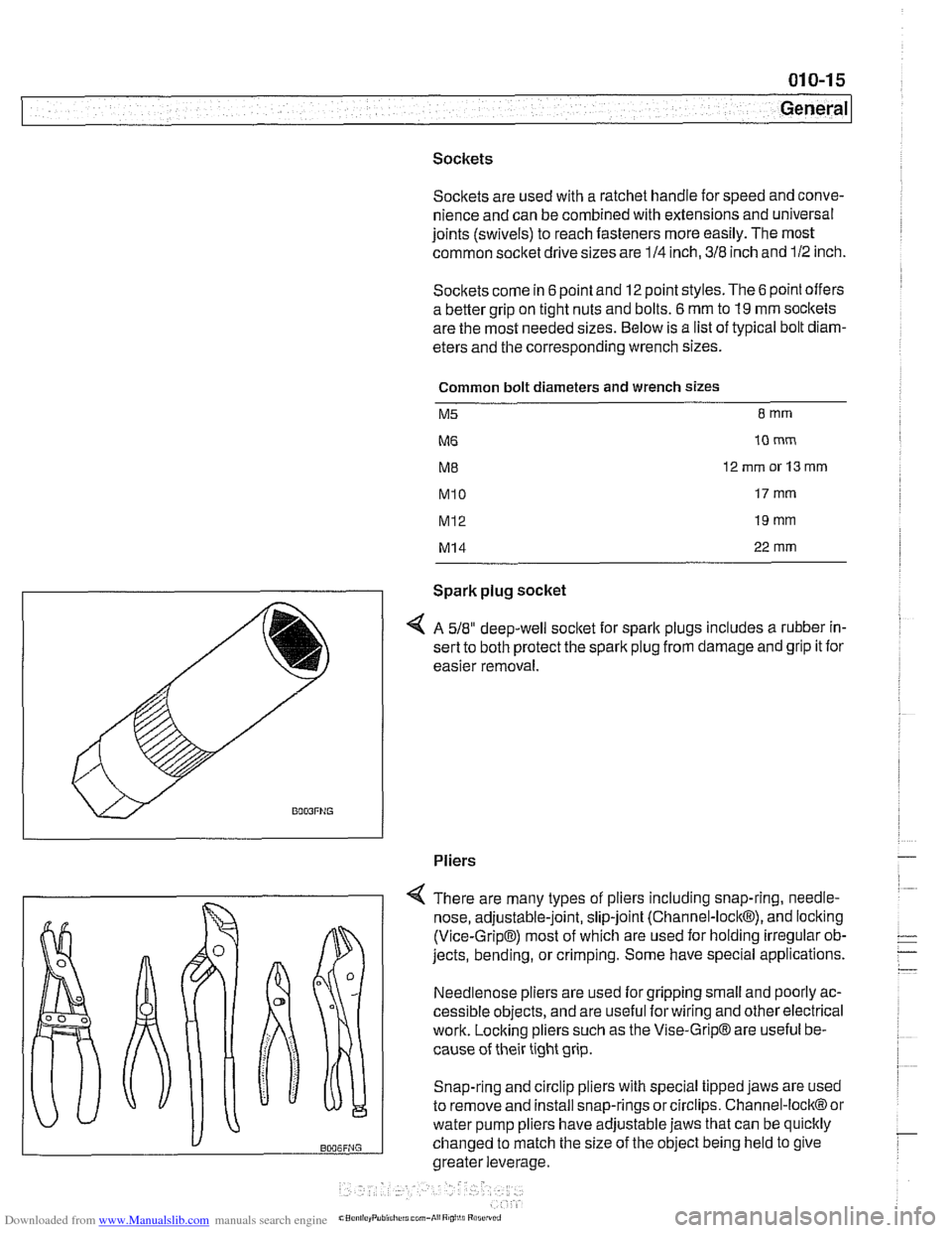
Spark plug socket
4 A 518" deep-well socket for sparlt plugs includes a rubber in-
sert to both protect the spark plug from damage and grip it for
easier removal.
Pliers
There are many types of pliers including snap-ring,
needle-
nose, adjustable-joint, slip-joint (Channel-lock@), and locking
(Vice-Grip@) most of which are used for holding irregular ob-
jects, bending, or crimping. Some have special applications.
Needlenose pliers are used for gripping small and poorly ac-
cessible objects, and are useful forwiring and other electrical
work. Locking pliers such as the Vise-Grip@ are useful be-
cause of their tight grip.
Snap-ring and circlip pliers with special tipped jaws are used
to remove and install snap-rings or circlips. Channel-lock@ or
water pump pliers have adjustable jaws that can be quicltly
changed to match the size of the object being held to give
greater leverage,
Page 27 of 1002
Downloaded from www.Manualslib.com manuals search engine
.
General
Torque wrench
A torque wrench is used to precisely tighten threaded fasten-
ers to a predetermined value. Many of the repair procedures
in this manual include BMW-specified torque values
in New-
ton-meters (Nm) and the equivalent values in foot-pounds
(ft-
Ib).
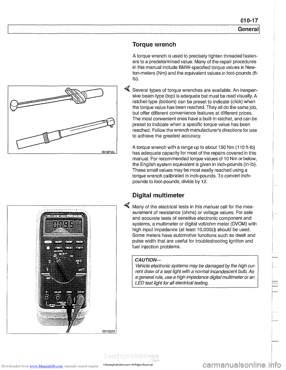
4 Several types of torque wrenches are available. An inexpen-
sive beam-type (top) is adequate but must be read visually. A
ratchet-type (bottom) can be preset to indicate (click) when
the torque value has been reached. They all do the same job,
but offer different convenience features at different prices.
The most convenient ones have a built-in ratchet, and can be
preset to indicate when a specific torque value has been
reached. Follow the wrench manufacturer's directions
for use
to achieve the greatest accuracy.
A torque wrench with a range up to about 150 Nm (1 10 ft-lb) BOIBFNG has adequate capacity for most of the repairs covered in this
manual. For recommended torque values of
10 Nm orbelow,
the English system equivalent is given in inch-pounds (in-lb).
These small values may be most easily reached using a
torque wrench calibrated in inch-pounds. To convert
inch-
pounds to foot-pounds, divide by 12.
Digital multimeter
4 Many of the electrical tests in this manual call for the mea-
surement of resistance (ohms) or voltage values. For safe
and accurate tests of sensitive electronic component and
systems, a multimeter or digital
volt/ohm meter (DVOM) with
high input impedance (at least
10,000Sr) should be used.
Some meters have automotive functions such as dwell and
pulse width that are useful for troubleshooting ignition and
fuel injection problems.
CAUTIOI\C
Vehicle electronic systems may be damaged by the high cur-
rent draw of a test light with a normal incandescent bulb. As
a general rule, use a high impedance digital multimeter or an
LED test light for all electrical testing.
Page 40 of 1002
Downloaded from www.Manualslib.com manuals search engine
--- -
Maintenance
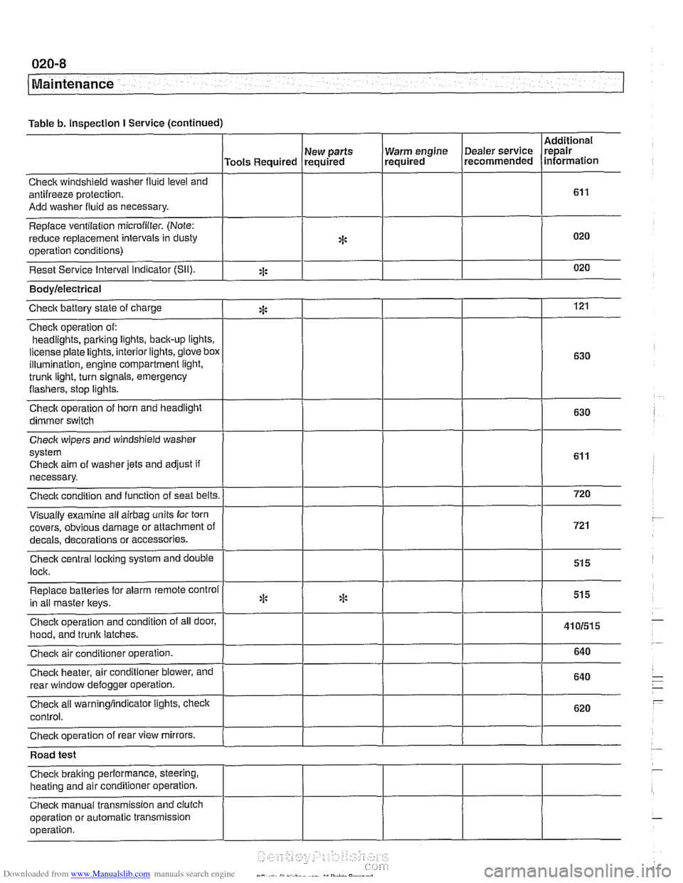
Table b. Inspection I Service (continued)
I I I I
Warm engine Dealer service
required recommended
Check windshield
washer fluid level and
antifreeze protection.
Add washer fluid as necessary.
Replace ventilation
microfilter. (Note:
reduce replacement intervals in dusty
operation conditions)
Reset Service interval Indicator
(Sil).
Additional
repair
information
Tools Required
*
eck aim of washer jets and adjust if
necessary.
covers, obvious damage or attachment o
s or accessories.
Road test
Check braking performance, steering,
heating and air conditioner operation.
Check manual transmission and clutch
operation or automatic transmission
operation. New
parts
required
*
Bodylelectrical
121
630
630
Checic battery state of charge
Check operation of:
headlights,
parking iights, back-up lights.
license plate lights, interior lights,
glove box
illumination, engine compartment light,
trunk light, turn signals, emergency
flashers, stop iights.
Check operation of horn and headlight
dimmer switch
:i:
Page 71 of 1002
Downloaded from www.Manualslib.com manuals search engine
Two common causes of driveability problems are incorrect
system voltage and bad grounds.
System voltage
Digital motor electronics (DME) requires that the system (bat-
tery) voltage be maintained within a narrow range of DC volt-
age.
DC voltage levels beyond or below the operating range,
or any
AIC voltage in the electrical system can cause havoc.
When troubleshooting an illuminated MIL, make sure the bat-
tery is fully charged and capable of delivering all its power to
the electrical system. An undercharged battery can amplify
AIC alternator output ripple.
To
make a quick check of the battery charge, measure the
voltage across the battery terminals with all cables attached
and the ignition off.
Afully charged battery will measure 12.6
volts or slightly more, compared to 12.1 5 volts for a battery
with a 25% charge.
The DME system operates at low voltage and current levels,
making it sensitive to small increases in resistance. The elec-
trical system is routinely subjected to corrosion, vibration and
wear, so faults or corrosion in the wiring harness and connec-
tors are not uncommon. Check the battery terminals
forcorro-
sion or loose cable connections. See 121 Battery, Starter,
Alternator for additional information.
If a battery cable connection has no
v~sible faults but is still
suspect, measure the voltage drop across the connection. A
large drop indicates excessive resistance, meaning that the
connection is corroded, dirty, or damaged. Clean or repairthe
connection and retest.
NOTE-
For instructions on conducting a voltage drop test and other
general electrical troubleshooting information, see
600 Elec-
trical System-General.
Visually inspect all wiring, connectors, switches and fuses in
the system. Loose or damaged connectors can cause inter-
mittent problems, especially the small terminals in the ECM
connectors. Disconnect the wiring harness connectors to
check for corrosion, and use electrical cleaning spray to re-
move contaminants.
Main grounds
Good grounds are critical to proper DME operation. If a
ground connection has no visible faults but is still suspect.
measure the voltage drop across the connection. A large volt-
age drop means high resistance. Clean or repair the connec-
tion and retest.
LBuntr.yP~sbhnllcn.can#-AII A,~iltl Rcsrwsd
Page 72 of 1002
Downloaded from www.Manualslib.com manuals search engine
100-6
( Engine-General
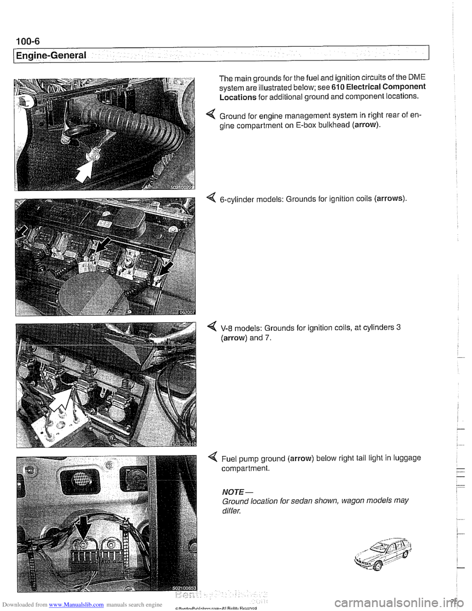
The main grounds for the fuel and ignition circuits of the DME
system are illustrated below; see 610 Electrical Component
Locations for additional ground and component locations.
4 Ground for engine management system in right rear of en-
gine compartment on E-box bulkhead (arrow).
6-cylinder models: Grounds
for ignition coils (arrows)
4 V-8 models: Grounds for ignition coils, at cylinders 3
(arrow) and 7.
4 Fuel pump ground (arrow) below right tail light in luggage
compartment.
NOTE-
Ground location for sedan shown, wagon models may
differ.
Page 76 of 1002
Downloaded from www.Manualslib.com manuals search engine
11 0-4
/Engine Removal and Installation
- Disconnect negative (-) cable from battery.
CAUTION- Prior to disconnecting the
batteg read the battery discon-
nection cautions
in 001 General Cautions and Warnings.
- Remove engine hood, or place in service position. See 410
Fenders, Engine Hood.
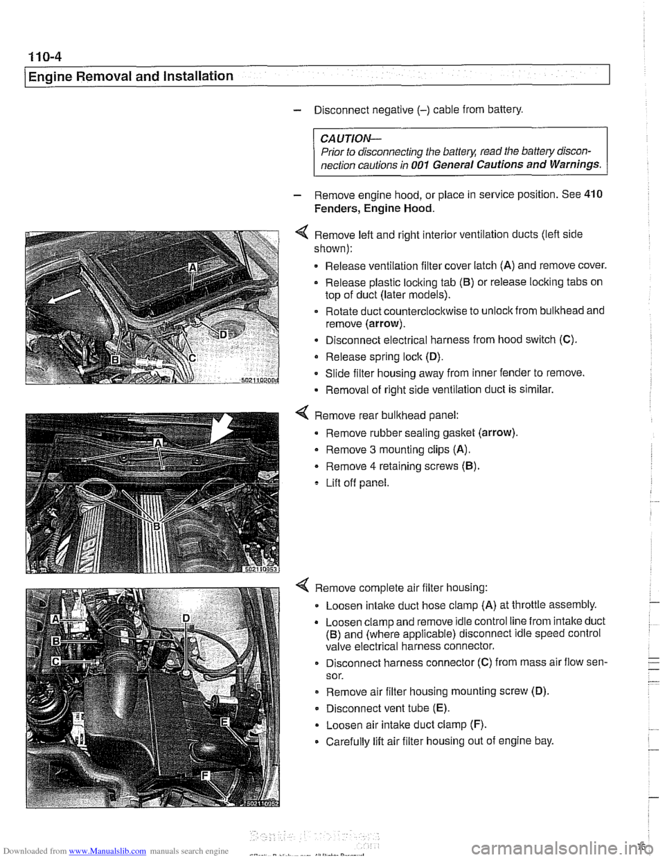
4 Remove left and right interior ventilation ducts (lefl side
shown):
Release ventilation filter cover latch (A) and remove cover.
Release plastic loclting tab
(6) or release locking tabs on
top of duct (later models).
Rotate duct counterclocltwise to
unloclt from bulkhead and
remove (arrow).
Disconnect electrical harness from hood switch (C).
Release spring
loclt (D).
Slide filter housing away from inner fender to remove.
Removal of right side ventilation duct is similar.
Remove rear bulkhead panel:
Remove rubber sealing gasket (arrow).
- Remove 3 mounting clips (A).
Remove
4 retaining screws (6).
Lift off panel.
Remove complete air filter housing:
Loosen
intalte duct hose clamp (A) at throttle assembly.
Loosen clamp and remove idle control line from intalte duct
(6) and (where applicable) disconnect idle speed control
valve electrical harness connector.
Disconnect harness connector (C) from mass air flow sen-
sor.
Remove air filter housing mounting screw (D).
Disconnect vent tube
(E).
Loosen air intake duct clamp (F).
Carefully lift air filter housing out of engine bay.
Page 77 of 1002
Downloaded from www.Manualslib.com manuals search engine
Engine Removal and lnstallationl
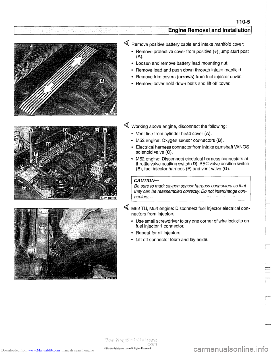
< Remove positive battery cable and intake manifold cover:
Remove protective cover from positive (+)jump start post
(4.
Loosen and remove battery lead mounting nut.
Remove lead and push down through intake manifold
Remove trim covers
(arrows) from fuel injector cover.
Remove cover hold down bolts and lift off cover.
Working above engine, disconnect the following:
Vent line from cylinder head cover (A).
M52 engine: Oxygen sensor connectors (8).
Electrical harness connector from intalte camshaft VANOS
solenoid valve
(C).
M52 engine: Disconnect electrical harness connectors at
throttle valve position switch
(D), ASC valve position switch
(E), fuel injector harness (F) and vent valve (G).
CAUTION-
Be sure to mark oxygen sensor harness connectors so that
they can be reassembled correctly Do not interchange con-
nectors.
4 M52 TU, M54 engine: Disconnect fuel injector electrical con-
nectors from injectors.
Use small screwdriverto pry one corner of wire lock clip on
fuel injector
1 connector.
Repeat for all injectors.
Lifl off connector loom and lay aside.
Page 80 of 1002
Downloaded from www.Manualslib.com manuals search engine
110-8
1 Engine Removal and Installation
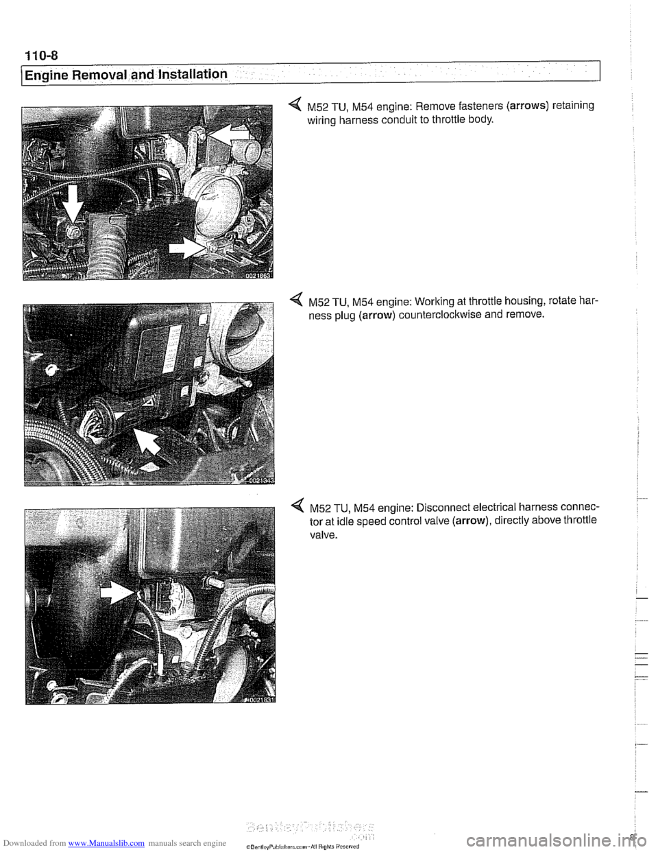
4 M52 TU, M54 engine: Remove fasteners (arrows) retaining
wiring harness conduit to throttle body.
4 M52 TU, M54 engine: Working at throttle housing, rotate har-
ness plug (arrow) counterclockwise and remove.
4 M52 TU, M54 engine: Disconnect electrical harness connec-
tor at idle speed control valve (arrow), directly above throttle
valve.
Page 81 of 1002
Downloaded from www.Manualslib.com manuals search engine
Engine Removal and lnstallationl
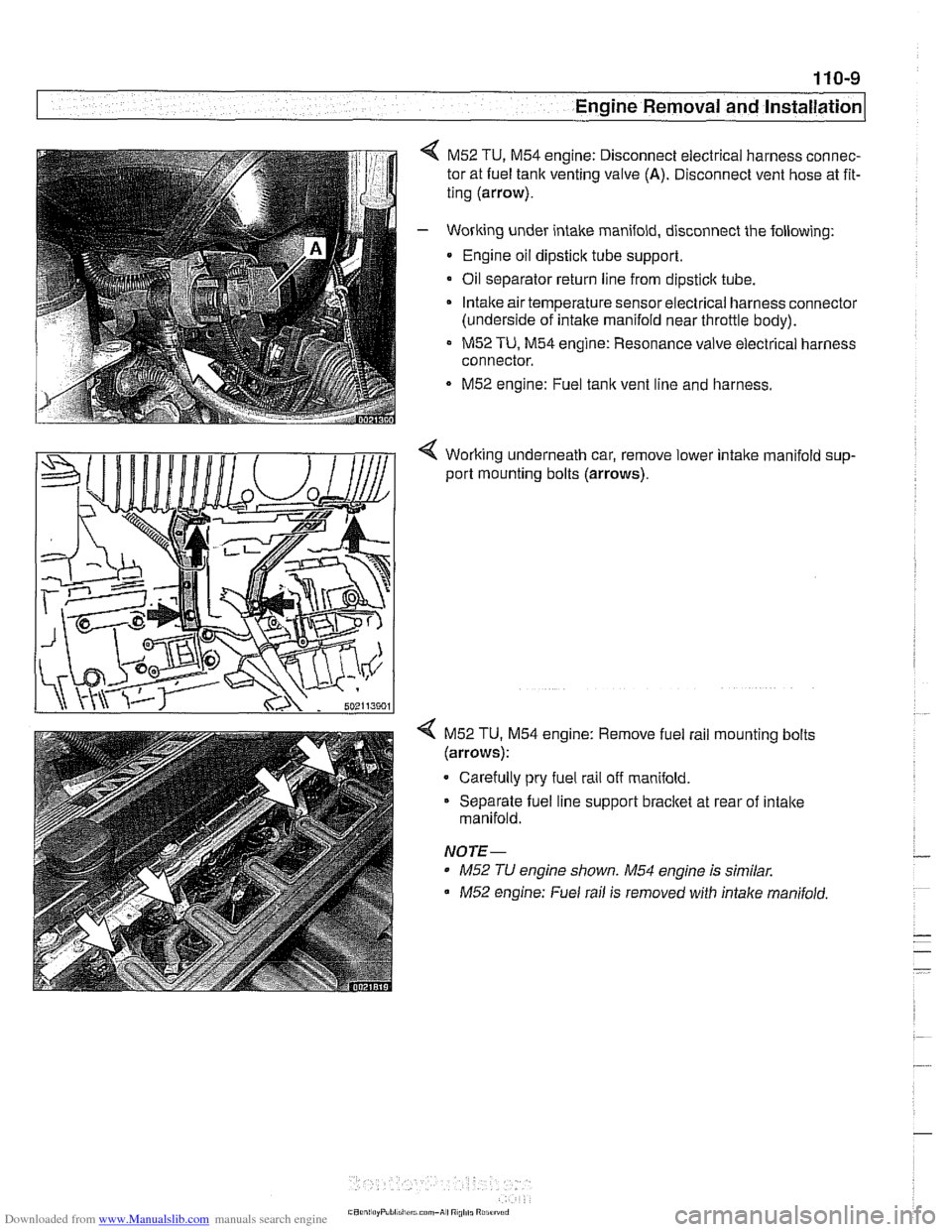
M52 TU, M54 engine: Disconnect electrical harness connec-
tor at fuel tank venting valve
(A). Disconnect vent hose at fit-
ting (arrow).
- Working under intake manifold, disconnect the following:
Engine oil dipstick tube support.
Oil separator return line from
dipsticlc tube.
Intake air temperature sensorelectrical harness connector
(underside of intake manifold near throttle body).
M52 TU, M54 engine: Resonance valve electrical harness
connector.
M52 engine: Fuel tank vent line and harness.
< Working underneath car, remove lower intalte manifold sup-
port mounting bolts (arrows).
4 M52 TU. M54 engine: Remove fuel rail mounting bolts
(arrows):
Carefully pry fuel rail off manifold.
Separate fuel line support bracket at rear of intake
manifold.
NOTE-
* M52 TU engine shown. M54 engine is similar.
M52 engine: Fuel rail is removed with intalte manifold.
Page 82 of 1002
Downloaded from www.Manualslib.com manuals search engine
.-
-6val and Installation -
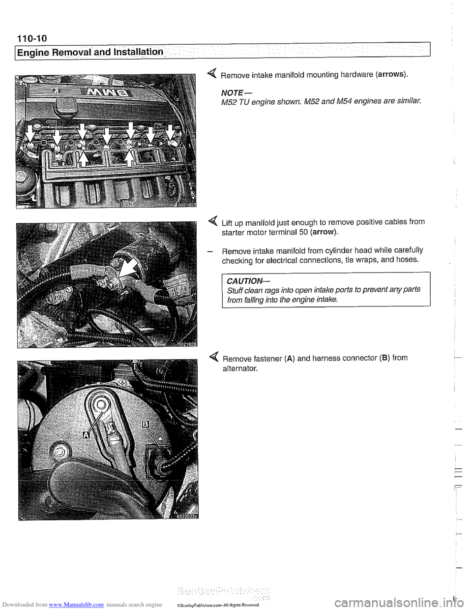
< Remove intake manifold mounting hardware (arrows).
NOTE-
M52 TU engine shown. M52 and M54 engines are similar.
Liit up manifold just enough to remove positive cables from
starter motor terminal
50 (arrow).
- Remove intake manifold from cylinder head while carefully
checking for electrical connections, tie wraps, and hoses.
CAUTION-
Stuff clean rags into open intake ports to prevent any parts
from falling into the engine intake.
4 Remove fastener (A) and harness connector (B) from
alternator.