Front BMW 525i 2001 E39 Owner's Manual
[x] Cancel search | Manufacturer: BMW, Model Year: 2001, Model line: 525i, Model: BMW 525i 2001 E39Pages: 1002
Page 114 of 1002
Downloaded from www.Manualslib.com manuals search engine
--
Cylinder Head Removal and Installation
NOTE-
BMW special tool 11 4 220 is an adjustable primary chain
tensioner and simulates the function of the hydraulic
tensioner.
- Check that elongated holes in primary sprocket are now cen-
tered to bolt holes in camshaft and chain is free of slack. If
not, reposition sprocket to chain and reinstall.
- lnstall secondary timing chain guide and secondary chain
tensioner. Tighten mounting bolts (tensioner remains locked
down for now using
BMW special tool 11 3 292).
- Install cylinder identification trigger plate to front of intake
camshaft with studs.
- Install spacer to front of intake camshaft.
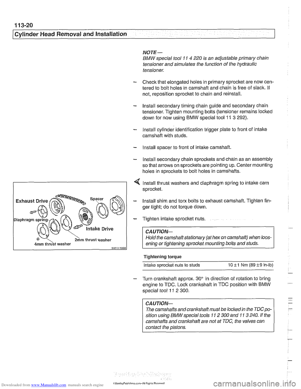
- Install secondary chain sprockets and chain as an assembly
so that arrows on sprockets are pointing up. Center mounting
holes in sprockets to bolt holes in camshafts.
4 lnstall thrust washers and diaphragm spring to intake cam
sprocket.
I 2hm thrust washer I
- Install shim and torx bolts to exhaust camshaft. Tighten fin-
ger tight; do not torque down.
- Tighten intake sprocket nuts.
CA UTIOG
Hold the camshaft stationary (at hex on camshaft) when loos-
enino or tiahtenino sorocket mounting bolts and studs.
Tightening torque
Intake s~rocket nuts to studs 10 +l Nm (89 +9 in-lb)
- Turn crankshaft approx. 30" in direction of rotation to bring
engine to TDC. Lock crankshaft in TDC position with BMW
special tool
11 2 300.
CAUTION-
The camshafts andcranlshaft must be lockedin the TDCpo-
sition using BMW special tools 11 2 300 and 11 3 240. If the
camshafts and cranl(shaft are not at TDC, the valves can
contact the pistons.
Page 115 of 1002
Downloaded from www.Manualslib.com manuals search engine
- -.
Cylinder Head Removal and lnstallation
NOTE-
Be Sure the secondary timing chain tensioner is locked down
and the exhaust
camshaif mounting bolts are loose before
proceeding.
- Install VANOS control unit. See VANOS control unit, install-
ing
(M52 engine) in 117 Camshaft Timing Chain.
CAUTION--
Incorrect installation ofthe VANOS control may result in dam-
age to the engine valvefrain.
- Install exhaust manifolds using new gaskets and nuts. Coat
manifold studs with copper paste prior to installing nuts.
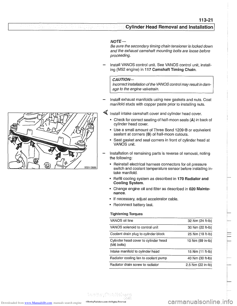
Install intake camshaft cover and cylinder
head cover.
Check for correct seating of half-moon seals
(A) in back of
cylinder head cover.
Use a small amount of Three Bond 1209
O or equivalent
sealant at corners
(6) of half-moon cutouts.
Seat gasket and seal corners in front of cylinder head at
VANOS unit.
- Installation of remaining parts is reverse of removal, noting
the following:
Reinstall electrical harness connectors for oil pressure
switch and coolant temperature sensor before installing in-
take manifold.
Refill cooling system as described in 170 Radiator and
Cooling System.
Change engine oil and filter as described in 020 Mainte-
nance.
If necessary, adjust accelerator cable.
Reconnect battery last.
Tightening Torques
VANOS oil line
32 Nm (24
ft-lb)
VANOS solenoid to control unit 30 Nm (22 ft-lb)
Coolant drain plug to cylinder
block 25 Nm (18 ft-lb)
Cylinder head cover to cylinder head
10 Nrn (89 in-lb)
(M6 bolts)
intake manifold to cylinder head 15 Nm (I 1 ft-lb)
Radiator cooling fan to coolant pump
40 Nm (30 ft-lb) - . .
Radiator drain screw to radiator 2.5 Nm (22 in-lbl
Page 117 of 1002
Downloaded from www.Manualslib.com manuals search engine
- --
Cylinder Head Removal and Installation 1 --
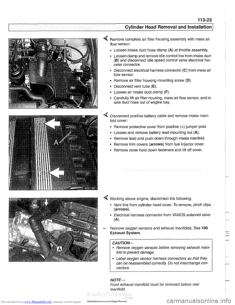
< Remove complete air filter housing assembly with mass air
flow sensor:
Loosen
intalte duct hose clamp (A) at throttle assembly.
Loosen clamp and remove idle control line from intake duct
(B) and disconnect idle speed control valve electrical har-
ness connector.
Disconnect electrical harness connector
(C) from mass air
flow sensor.
Remove air filter housing mounting screw
(D).
Disconnect vent tube (E).
. Loosen air intalte duct clamp (F).
Carefully lifl air filter housing, mass air flow sensor, and in-
take duct hose out of engine bay.
4 Disconnect positive battery cable and remove intake rnani-
fold cover:
Remove protective cover from positive (+)jumper post.
Loosen and remove battery lead mounting nut (A).
Remove lead and push down through intake manifold.
* Remove trim covers (arrows) from fuel injector cover.
Remove cover hold down fasteners and lifl off cover.
4 Worlting above engine, disconnect the following:
Vent line from cylinder head cover. To remove, pinch clips
(arrows).
Electrical harness connector from VANOS solenoid valve
(A).
- Remove oxygen sensors and exhaust manifolds. See 180
Exhaust System.
CAUTION-
Remove oxygen sensors before removing exhaust mani-
fold to prevent damage.
Label oxygen sensor harness connectors so that they
can be reassembled correctly Do not interchange con-
nectors.
NOTE-
Front exhaust manifold must be removed before rear
manifold.
Page 128 of 1002
Downloaded from www.Manualslib.com manuals search engine
- -
I Cylinder Head emo oval and Installation -
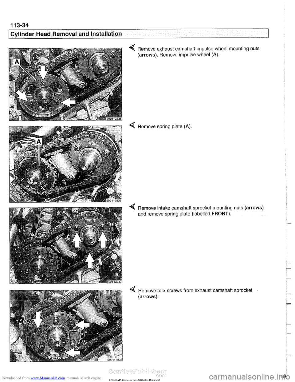
< Remove exhaust camshaft impulse wheel mounting nuts
(arrows). Remove impulse wheel
(A).
4 Remove spring plate (A).
4 Remove intake camshaft sprocltet mounting nuts (arrows)
and remove spring plate (labelled
FRONT).
< Remove torx screws from exhaust camshaft sprocket
(arrows).
Page 139 of 1002
Downloaded from www.Manualslib.com manuals search engine
Cylinder Head Removal and Installation
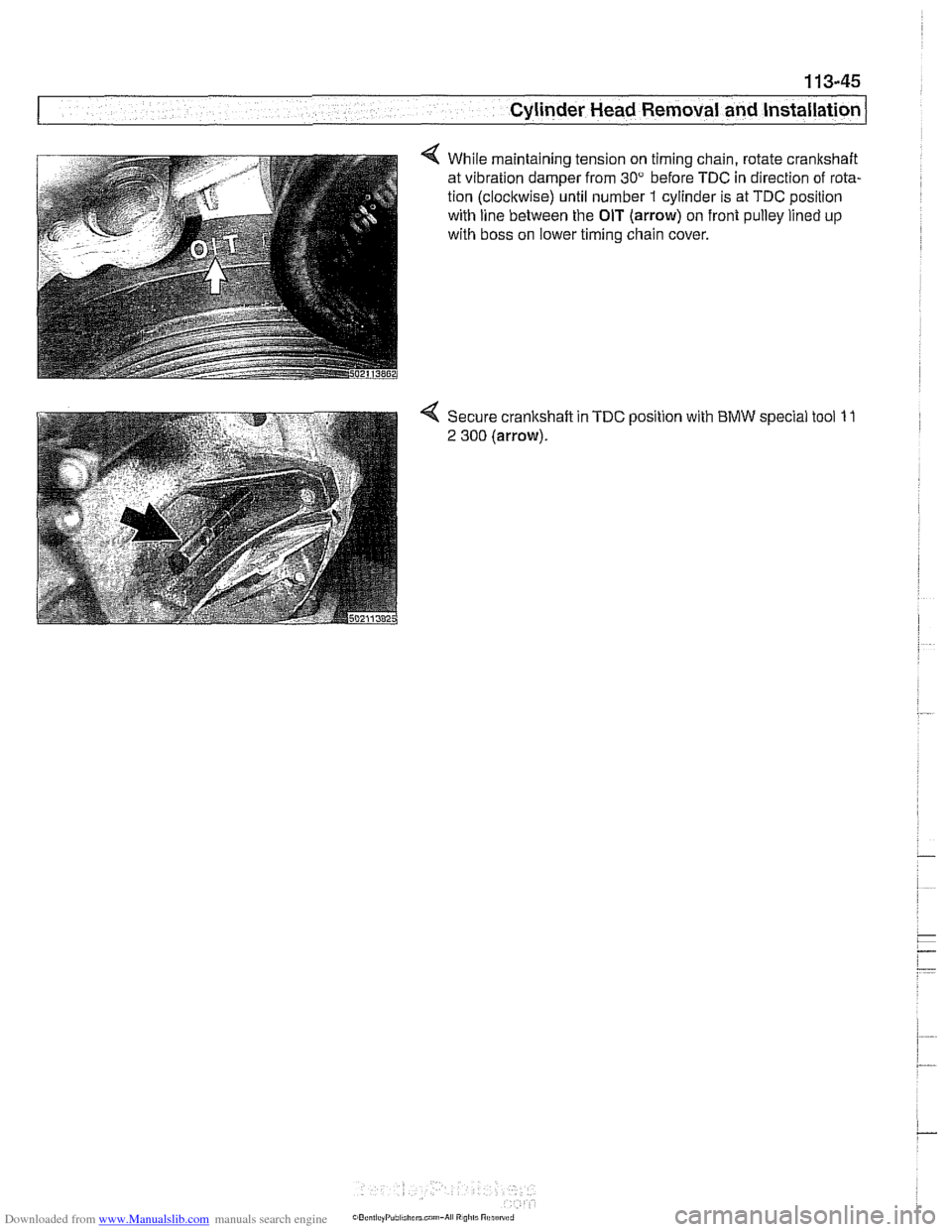
4 While maintaining tension on timing chain, rotate crankshaft
at vibration damper from
30" before TDC in direction of rota-
tion (clockwise) until number
1 cylinder is at TDC position
with line between the
OIT (arrow) on front pulley lined up
with boss on lower timing chain cover.
Page 143 of 1002
Downloaded from www.Manualslib.com manuals search engine
-7 Cylinder Head Removal and lnstallat~on -- -- - -
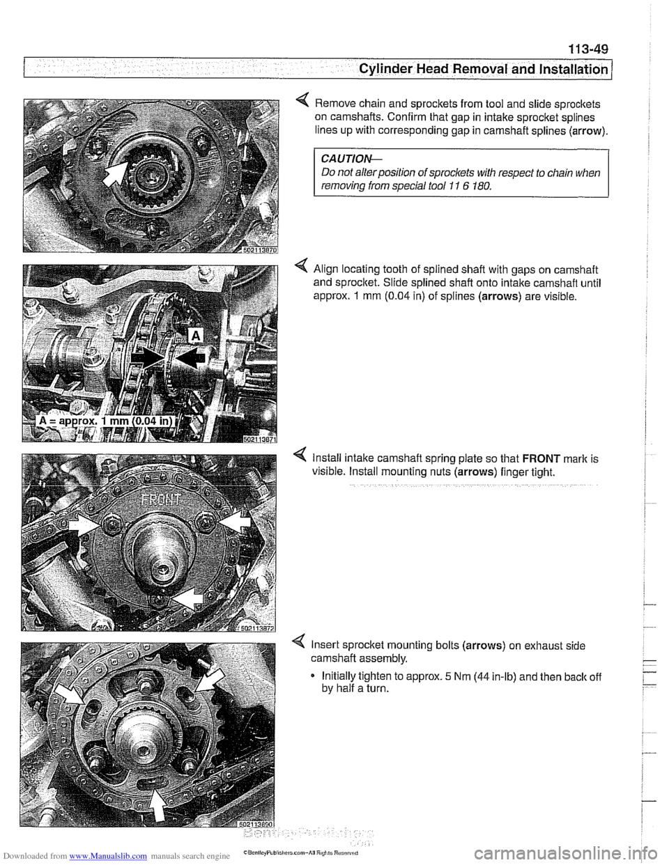
Remove chain and sprockets from tool and slide sprockets
on camshafts. Confirm that gap in intake sprocket splines
lines up with corresponding gap in camshaft splines (arrow).
CAUTIOI\C
Do not alter position of sprockets with respect to chain when
removing
from special tool 11 6 180.
< Align locating tooth of splined shaft with gaps on camshaft
and sprocket. Slide splined shaft onto intake camshaft until
approx.
1 mm (0.04 in) of splines (arrows) are visible.
4 Install intake camshafl spring plate so that FRONT mark is
visible. Install mounting nuts (arrows) finger tight.
Insert sprocket mounting bolts (arrows) on exhaust side
camshaft assembly.
Initially tighten to approx.
5 Nm (44 in-lb) and then back off
by half a turn.
Page 145 of 1002
Downloaded from www.Manualslib.com manuals search engine
113-51
Cylinder Head Removal and Installation
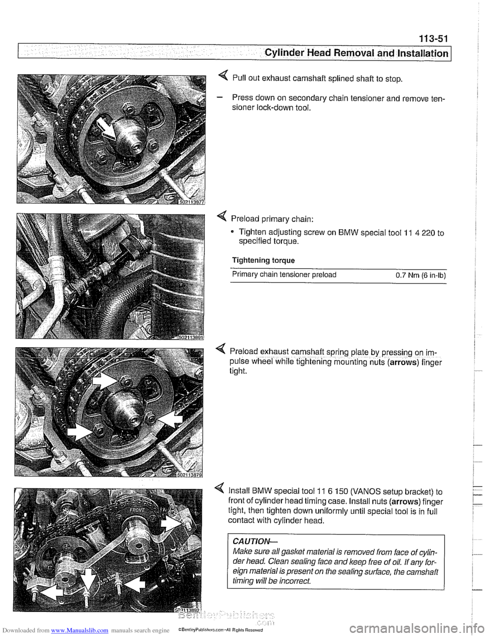
< Pull out exhaust camshaft splined shaft to stop.
- Press down on secondary chain tensioner and remove ten-
sioner lock-down tool.
Preload primary chain:
Tighten adjusting screw on
BMW special tool 11 4 220 to
specified torque.
Tightening torque
Primary chain tensioner preload
0.7 Nrn (6 in-lb)
< Preload exhaust camshaft sprrng plate by pressing on im-
pulse wheel while tightening mounting nuts (arrows) finger
tight.
Install BMW special tool 11 6 150 (VANOS setup bracket) to
front of cylinder head timing case. Install nuts (arrows) finger
tight, then tighten down uniformly until special tool is in full
contact with cylinder head.
CAUTION-
Make sure all gasket material is removed from face of cylin-
der head. Clean sealing
face and keep free of oil. If any for-
eign material is present on the sealing
sudace, the camshait
timina will be incorrect.
Page 146 of 1002
Downloaded from www.Manualslib.com manuals search engine
. .- --
Cylinder Head Removal and Installation
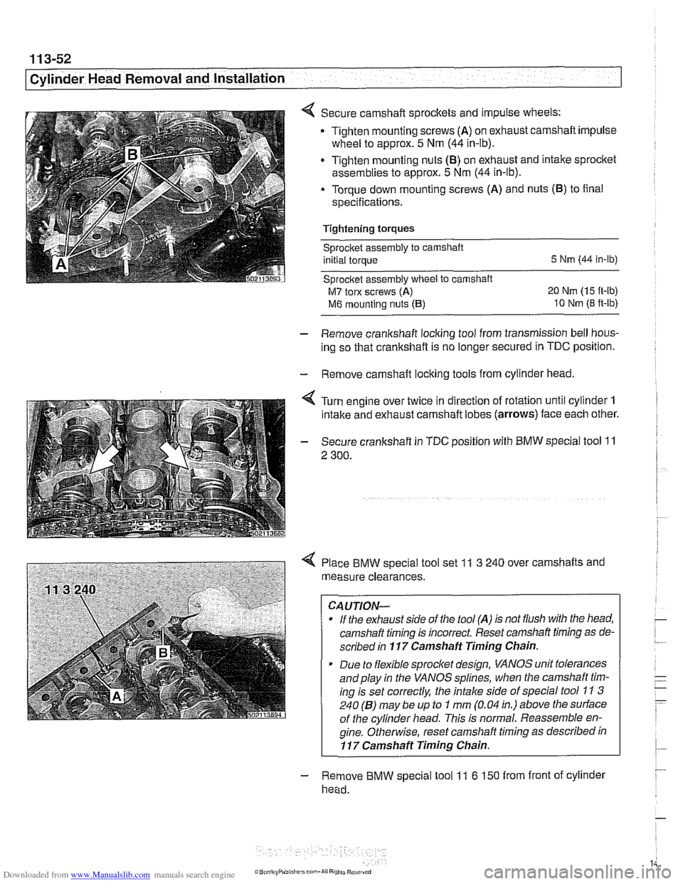
Secure camshaft sprockets and impulse wheels:
Tighten mounting screws
(A) on exhaust camshaft impulse
wheel to approx.
5 Nm (44 in-lb).
Tighten mounting nuts
(8) on exhaust and intake sprocket
assemblies to approx.
5 Nm (44 in-lb).
Torque down mounting screws (A) and nuts (B) to final
specifications.
Tightening torques
sprocket assembly to camshaft
initial torque
5 Nm (44 in-lb)
Sprocket assembly
wheel to camshaft
M7 torx screws (A) 20 Nm (15 ft-lb)
M6 mounting nuts (5) 10 Nm (8 ft-lb)
- Remove crankshaft locking tool from transmission bell hous-
ing so that crankshaft is no longer secured in
TDC position.
- Remove camshaft locking tools from cylinder head.
4 Turn engine over twice in direction of rotation until cylinder 1
intake and exhaust camshaft lobes (arrows) face each other.
- Secure crankshaft in TDC position with BMW special tool 11
2 300.
4 Place BMW special tool set 11 3 240 over camshafts and
measure clearances.
CAUTION-
- If the exhaust side of the tool (A) is not flush with tlie head,
camshaft timing is incorrect Reset camshaft timing as de-
scribed in
117 Camshaft Timing Chain.
* Due to flexible sprocket design, VANOS unit tolerances
and play in the VANOS splines, when the camshaft tim-
ing is set correctly, the intake side of special tool
11 3
240 (6) may be up to 1 mm (0.04 in.) above the surface
of the cylinder head. This is normal. Reassemble en-
gine.
Othe~lise, reset camshaft timing as described in
11 7 Camshaft Timing Chain.
- Remove BMW special tool 11 6 150 from front of cylinder
head.
Page 147 of 1002
Downloaded from www.Manualslib.com manuals search engine
Cylinder Head Removal and Installation /
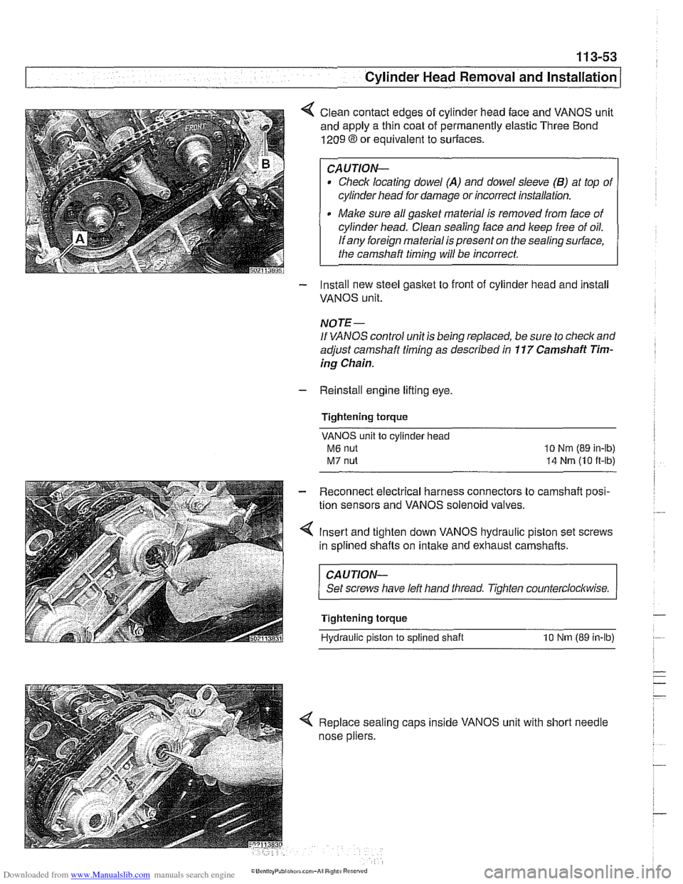
< Clean contact edges of cylinder head face and VANOS unit
and apply a thin coat of permanently elastic Three Bond
1209 8 or equivalent to suriaces.
CAUTION-
Check locating dowel (A) and dowel sleeve (B) at top of
cylinder head for damage or incorrect installation.
Make sure all gasket material is removed from face of
cylinder head. Clean sealing face and keep free of oil.
If any foreign material is present on the sealing surface,
the camshaft timing will be incorrect.
- Install new steel gasket to front of cylinder head and install
VANOS unit.
NOTE -
If VANOS control unit is being replaced, be sure to check and
adjust camshaft timing as described in
11 7 Camshaft Tim-
ing Chain.
- Reinstall engine lifting eye.
Tightening torque
VANOS unit to cylinder head
M6 nut
M7 nut
lo Nm (89 in-lb)
14 Nrn (10 it-lb)
- Reconnect electrical harness connectors to camshaft posi-
tion sensors and VANOS solenoid valves.
4 Insert and tighten down VANOS hydraulic piston set screws
in splined shafts on
intake and exhaust camshafts.
CAUJION-
Set screws have left hand tliread. Tighten counterclockwise.
Tightening torque
Hydraulic piston
to splined shaft 10 Nm (89 in-lb)
< Replace sealing caps inside VANOS unit with short needle
nose pliers.
Page 148 of 1002
Downloaded from www.Manualslib.com manuals search engine
. ." ".
[Cylinder Head Removal and Installation - .. - -1 -
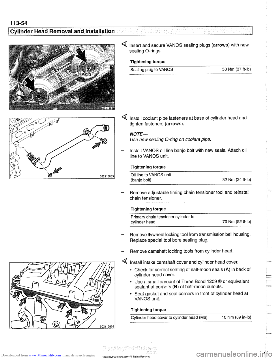
4 Insert and secure VANOS sealing plugs (arrows) with new
sealing O-rings.
Tightening torque Sealing
plug to VANOS 50
Nm (37 ft-lb)
4 Install coolant pipe fasteners at base of cylinder head and
tighten fasteners (arrows).
NOTE-
Use new sealing O-ring on coolant pipe.
- lnstall VANOS oil line banjo bolt with new seals. Attach oil
line to VANOS unit.
Tightening torque Oil line to VANOS unit
(banjo bolt) 32
Nm (24 ft-ib)
- Remove adjustable timing chain tensioner tool and reinstall
chain tensioner.
Tightening torque Primary chain tensioner cylinder to
cylinder head 70
Nm
(52 fi-ib)
- Remove flywheel locking tool from transmission bell housing.
Replace special tool bore sealing plug.
- Remove camshaft locking tools from cylinder head
4 lnstall intake camshaft cover and cylinder head cover.
0 Check for correct seating of half-moon seals (A) in back of
cylinder head cover.
Use a small amount of Three Bond
1209 8 or equivalent
sealant at corners
(B) of half-moon cutouts.
Seat gasket and seal corners in front of cylinder head at
VANOS unit.
Tightening torque
Cylinder head cover to cylinder head
(M6) 10 Nm (89 in-lb)