Air condition BMW 525i 2001 E39 Owner's Guide
[x] Cancel search | Manufacturer: BMW, Model Year: 2001, Model line: 525i, Model: BMW 525i 2001 E39Pages: 1002
Page 767 of 1002
Downloaded from www.Manualslib.com manuals search engine
Brakes
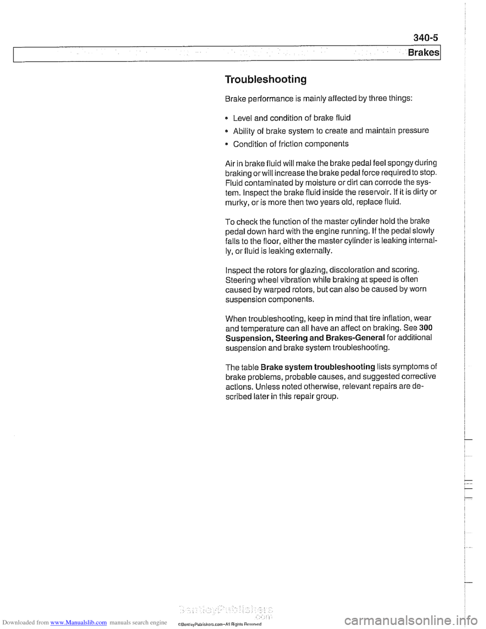
Troubleshooting
Brake performance is mainly affected by three things:
Q Level and condition of brake fluid
Ability of bralte system to create and maintain pressure
Condition of friction components
Air in bralte fluid will
make the brake pedal feel spongy during
braking
orwill increase the bralte pedal force required to stop.
Fluid contaminated by moisture or dirt can corrode the sys-
tem. lnspect the brake fluid inside the reservoir. If it is dirty or
murky, or is more then two years old, replace fluid.
To
check the function of the master cylinder hold the bralte
pedal down hard with the engine running. If the pedal slowly
falls to the floor, either the master cylinder is leaking internal-
ly, or fluid is leaking externally.
lnspect the rotors for glazing, discoloration and scoring.
Steering wheel vibration while braking at speed is often
caused by warped rotors, but can also be caused by worn
suspension components.
When troubleshooting, keep in mind that tire inflation, wear
and temperature can all have an affect on braking. See
300
Suspension, Steering and Brakes-General for additional
suspension and brake system troubleshooting.
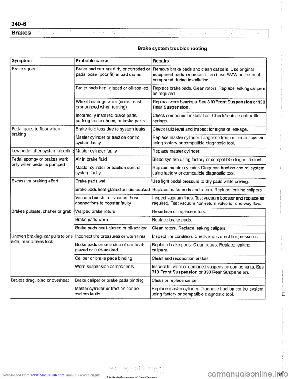
The table Brake system troubleshooting lists symptoms of
brake problems, probable causes, and suggested corrective
actions. Unless noted otherwise, relevant repairs are de-
scribed later in this repair group.
Page 768 of 1002
Downloaded from www.Manualslib.com manuals search engine
340-6
1 Brakes
Brake system troubleshooting
/symptom I Probable cause 1 Repairs
Brake squeal
Pedal goes to floor when
bralting
Low pedal after system bleeding
Pedal spongy or brakes work
only when pedal is pumped
Excessive braking effort
Brakes pulsate, chatter or grab
Uneven
bralting, car pulls to one
side, rear braltes
loclt
Brakes drag, bind or overheat Brake
pad carriers dirty or corroded or
pads loose (poor fit) in pad carrier
Braite pads heat-glazed or oil-soaked
Wheel bearings worn (noise most
pronounced when turning)
Incorrectly Installed brake pads,
parking bralte shoes, or bralte parts
Brake fluid loss due to system leaks
Master cylinder or traction control
system faulty
Master cylinder faulty
Air in braite fluid
Master cylinder or traction control
system faulty
Brake pads wet
Brake pads
heat-glazedorfluid-soalted
Vacuum booster or vacuum hose
connections to booster faulty
--- Warped brake rotors
Brake pads worn
Brake pads heat-glazed or oil-soaked Remove
brake pads and clean calipers. Use original
equipment pads for proper fit and use BMW anti-squeal
compound during installation,
Replace brake pads. Ciean rotors. Replace leaking caliper:
as required.
Replace worn bearings. See 310 Front Suspension
or33C
Rear Suspension.
Check component installation. Checldreplace anti-rattle
springs.
Checlt fluid level and inspect for signs of leakage.
Replace master cylinder. Diagnose traction control system
using factory or compatible diagnostic tool.
Replace master cylinder.
Bleed system using factory or compatible diagnostic tool.
Replace master cylinder. Diagnose traction control system
using factory or compatible diagnostic tool.
Use light pedal pressure to dry pads while driving.
Replace
bralte pads and rotors. Replace leaking calipers.
lnspect vacuum lines. Test vacuum booster and replace as
required. Test vacuum non-return valve for one-way flow.
Resurface or replace rotors.
Replace brake pads.
Clean rotors. Replace leaiting calipers.
Incorrect tire pressures or worn tires
Brake pads on one side of car heat-
glazed or fluid-soaked
Caliper or brake pads binding
Worn suspension components
Brake caliper or brake pads binding
Master cylinder or traction control
system faulty lnspect
tire condition. Checlt and correct tire pressures.
Replace brake pads. Clean rotors. Replace leaking
calipers.
Clean and recondition brakes.
Inspect for worn or damaged suspension components. See
310 Front Suspension or 330 Rear Suspension.
Ciean or replace caliper.
Replace master cylinder. Diagnose traction control system
using faclory or compatible diagnostic tool.
Page 778 of 1002
Downloaded from www.Manualslib.com manuals search engine
1 Brakes
Max. machine limit per
friction ring side 0.8 mm (0.03
in) I
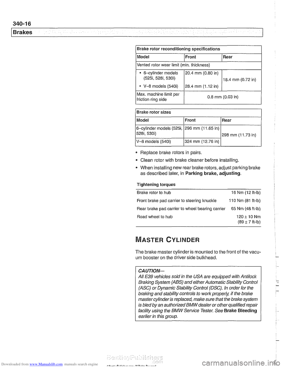
Brake rotor reconditioning specifications
Model
Replace
braite rotors in pairs
Bralre rotor sizes
Clean rotor with brake cleaner before installing.
Front
Model
6-cylinder
models (5251,
5281, 530i)
V-8 models (540i)
* When installing new rear brake rotors, adjust pariting brake
as described later, in Parking brake, adjusting. Rear
Vented rotor wear limit (min. thickness)
Tightening torques
Braite rotor to hub 16 Nm (12 ft-lb)
6-cylinder models
(525i, 5281, 530i)
- V-8 models (540i)
Front
296 mm (1 1.65 in)
324 mm (12.76 in)
Front bralte pad
carrler to steering ltnucitle 110 Nm (81 ft-lb)
Rear
298 mm (1 1.73 in)
Rear
brake pad carrier to wheel bearing carrier 65 Nm (48 ft-lb)
20.4
mm (0.80 in)
28.4 mm (1.12 in)
Road wheel to hub
120ilONm
(89 -t 7 it-lb)
18.4 mm (0.72 in)
The brake master cylinder is mounted to the front of the vacu-
um booster on the driverside bullthead.
-
CAUTION-
All E39 vehicles soldin the USA are equipped with Antilock
Braling System (ABS) and either Automatic Stability Control
(ASC) or Dynamic Stability Control (DSC).
In order for the
braling and stability controls to work properk if the brake
master cylinder is replaced, make sure that the brake system
is bled
by an authorized BMW dealer or other qualified repair
facility
using the BMW Service Tester. See Brake Bleeding
earlier
in this group.
Page 795 of 1002
Downloaded from www.Manualslib.com manuals search engine
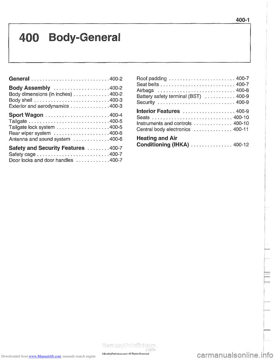
400 Body-General
........................ General ........................... .40 0.2 Roof paddin~ 400-7
Body Assembly ................... .40 0.2
Body dimensions (in inches)
............ .40 0.2
Bodyshell
........................... 400-3
Exterior and aerodynamics
............. .40 0.3
Sport Wagon ...................... .40 0.4
Tailgate
............................ .40 0.5
Tailgate lock system
.................. .40 0.5
Rear wiper system ................... .40 0.6
Antenna and sound system ............ .40 0.6
Safety and Security Features ....... .40 0.7
Safety cage
......................... .40 0.7
Door locks and door handles
........... .40 0.7
.
........................... Seat belts 400-7
Airbags ............................ 400-8
Battery safety terminal (BST)
........... 400-9
Security
............................ 400-9
Interior Features ................... 400-9
............................. Seats 400-10
Instruments and controls .............. 400-10
Central body electronics
.............. 400-1 1
Heating and Air
Conditioning (IHKA)
............... 400-12
Page 801 of 1002
Downloaded from www.Manualslib.com manuals search engine
Body-General
SAFETY AND SECURITY FEATURES
A number of new or improved safety and security features are
incorporated in
E39 cars.
Safety cage
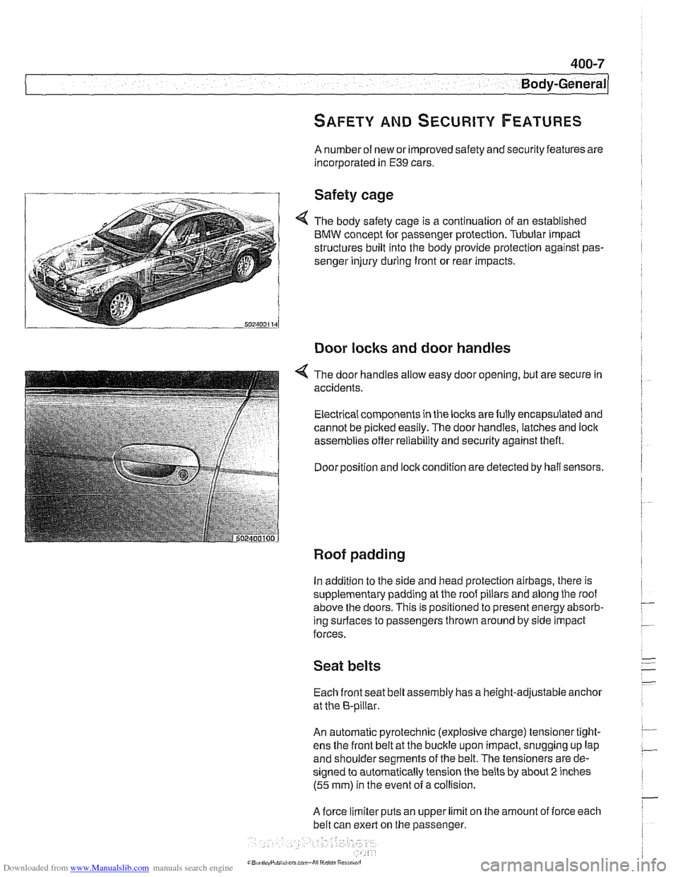
4 The body safety cage is a continuation of an established
BMW concept for passenger protection. Tubular impact
structures built into the body provide protection against pas-
senger injury during front or rear impacts.
Door locks and door handles
4 The door handles allow easy door opening, but are secure in
accidents.
Electrical components in the locks are fully encapsulated and
cannot be picked easily. The door handles, latches and
loclc
assemblies offer reliability and security against theft.
Door position and
loclc condition are detected by hall sensors.
Roof padding
In addition to the side and head protection airbags, there is
supplementary padding at the roof pillars and along the roof
above the doors. This is positioned to present energy absorb-
ing
surlaces to passengers thrown around by side impact
forces.
Seat belts
Each front seat belt assembly has a height-adjustable anchor
at the 8-pillar.
An automatic pyrotechnic (explosive charge) tensioner tight-
ens the front belt at the buckle upon impact, snugging up lap
and shoulder segments of the belt. The tensioners are de-
signed to automatically tension the belts by about
2 inches
(55 mm) in the event ofa collision.
A force limiter puts an upper limit on the amount of iorce each
belt can exert on the passenger.
Page 806 of 1002
Downloaded from www.Manualslib.com manuals search engine
400-12
I Body-General
HEATING AND AIR ~ONDITIONING
(I H KA)
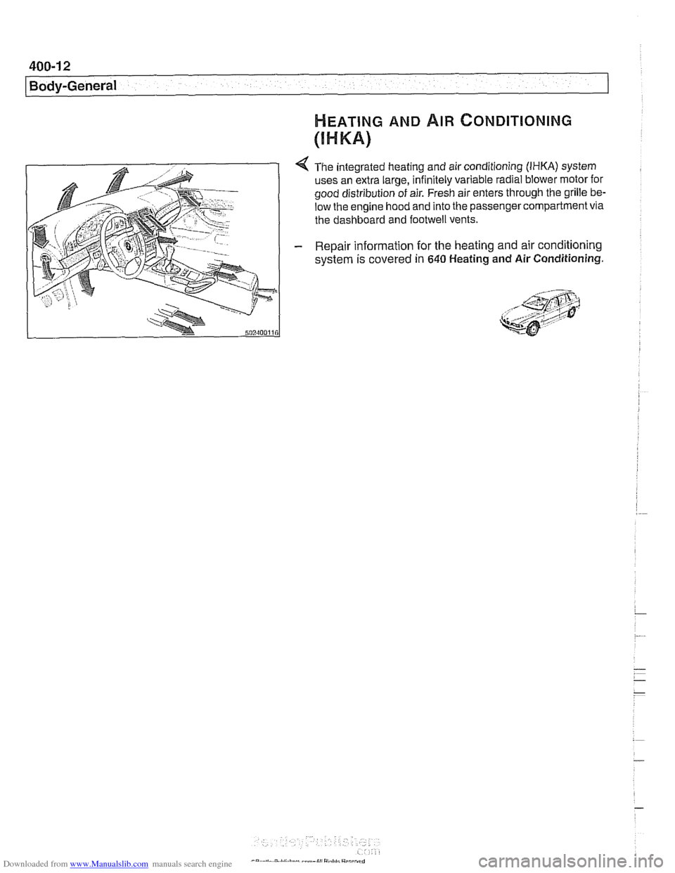
4 The integrated heating and air conditioning (IHKA) system
uses an extra large, infinitely variable radial blower motor for
good distribution of air. Fresh air enters through the grille
be.
low the engine hood and into the passenger compartment via
the dashboard and
footwell vents.
- Repair information for the heating and air conditioning
system is covered
in 640 Heating and Air Conditioning.
Page 880 of 1002
Downloaded from www.Manualslib.com manuals search engine
I lnterior Trim
This repair group covers interior trim removal and installation
procedures.
- Refer to the following repair groups for additional information:
250 Gearshift Linkage
41 1 Doors (interior door panels)
@ 612 Switches
620 Instruments
640 Heating and Air Conditioning [IHKA control panel!
650 Radio
721 Airbag System (SRS)
lnterior trim repairs
lnterior trim and finish panels are clipped or screwed into
place. Many of the trim retaining clips are designed
to be used
only once. When removing trim that is held in place with clips,
it is a good idea to have spare clips on hand before beginning
the job.
WARNING-
Special precautions must be observed when servicing the
BMWSupplementai Restraint System (SRS). Serious inju-
ry may result if system service is attempted by persons un-
familiar with the BMW
SRS and its approved service
procedures. BMW
speciiies that all inspection and service
should be performed by an authorized BMW
dealer.
Before performing any work involving airbags, discon-
nect the negative
() battery cable. See 721 Airbag
System (SRS).
Airbags contain a back-uppowersupply within the SRS
control module. A
5 second discharge period should be
allowed after the battery cable has been disconnected.
CAUTION-
* When working on electrical switclies or lights, always dis-
connect the negative
(-) cable from the battery and insu-
late the cable end to prevent accidental reconnection.
a Prior to disconnecting the battery, read the battery dis-
connection cautions given in
W1 General Warnings
and Cautions.
To prevent marring the trim when working on interior
components, work with plastic prying
tools or wrap the
tips of screwdrivers and pliers with tape before prying
Page 962 of 1002
Downloaded from www.Manualslib.com manuals search engine
OED-2
On-Board Diagnostics
Specialized OED II scan tool equipment is needed to access
the fault memory and
OED I1 data.
The extra hardware needed to operate the OED
I1 system
consists mainly of the following:
* Additional oxygen sensors downstream of the catalytic
converters.
Fuel tank pressure sensor and device to pressurize
fuel
storage system.
Several engine and performance monitoring devices
Standardized 16-pin
OED II connector under the
dashboard.
Upgraded components for the federally required reliability
mandate.
Malfunction indicator light (MIL)
OED II software illuminates the malfunction indicator light
(MIL) when emission levels exceed 1.5 times Federal
standards.
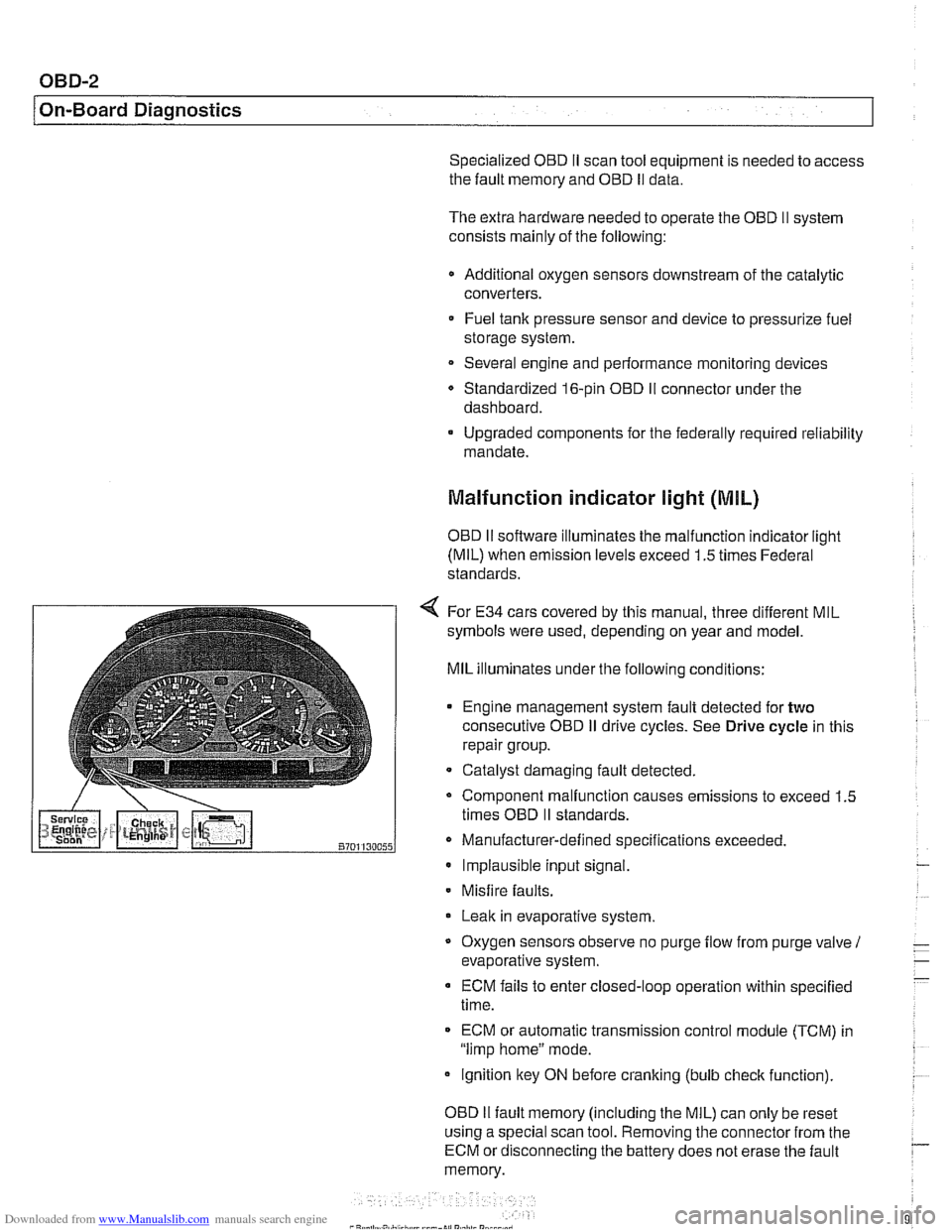
4 For E34 cars covered by this manual, three different MIL
symbols were used, depending on year and model.
MIL illuminates under the following conditions:
Engine management system fault detected for
two
consecutive OED iI drive cycles. See Drive cycle in this
repair group.
- Catalyst damaging fault detected.
Component malfunction causes emissions to exceed 1.5
times OED
II standards.
Manufacturer-defined specifications exceeded. Implausible input signal.
Misfire
faults.
Leak in evaporative system,
Oxygen sensors observe no purge
flow from purge valve 1
evaporative system.
ECM fails to enter closed-loop operation within specified
time.
ECM or automatic transmission control
module (TCM) in
"limp home" mode.
ignition key ON before cranking (bulb
check function).
OED
II fault memory (including the MIL) can only be reset
using a special scan tool. Removing the connector from the
ECM or disconnecting the battery does not erase the fault
memory.
Page 964 of 1002
Downloaded from www.Manualslib.com manuals search engine
- -
On-Board Diagnostics
Professional diagnostic scan tools available atthe time of this
printing include the BMW factory tools
(DISplus, GTI,
MoDiC) and a small number of aftermarket BMW-specific
tools. See
020 Maintenance.
In addition to the professional line of scan tools, inexpensive
generic OBD
II scan tool software programs and handheld
units are readily available. Though limited, they are
nonetheless powerful diagnostic tools. These tools read live
data streams and freeze frame data as well as a host of other
valuable diagnostic data.
Diagnostic monitors
Diagnostic monitors run tests and checks on specific
emission control systems, components, and functions.
A complete drive cycle is requiredforthe tests to bevalid. See
Drive cycle in this repair group. The diagnostic monitor
signals the
ECM of the loss or impairment of the signal or
component and determines if a signal or sensor is faulty
based on
3 conditions:
* Signal or component shorted to ground
Signal or component shorted to
B+
Signal or component missing (open circuit)
The OBD
II system monitors all emission control systems that
are installed. Emission control systems vary by vehicle model
and year. For example, a vehicle may not be equipped with
secondary air injection, so no secondary air readiness code
would be present.
OBD
II software monitors the following:
Oxygen sensors
Catalysts
Engine misfire
- Fuel tank evaporative control system
Secondary air injection Fuel system
Oxygen sensor monitoring. When driving conditions allow,
response rate and switching time of each oxygen sensor is
monitored. The oxygen sensor heater function is also
monitored. The OBD
II system differentiates between
precataylst and post-catalyst oxygen sensors and reads each
one individually. In order
forthe oxygen sensor to be
effectively monitored, the system must be in closed loop
operation.
Page 965 of 1002
Downloaded from www.Manualslib.com manuals search engine
On-Board Diagnostics
Catalyst monitoring. Thisstrategy monitors the outputofthe
precatalyst and post-catalyst oxygen sensors, comparing the
oxygen content going into the catalytic converter to the
oxygen leaving the converter.
The diagnostic executive
lknows that most of the oxygen
should be used up during the oxidation phase. If it detects
higherthan programmed values, afault is set and the MIL
illuminates.
Misfire detection. This strategy monitors crankshaft speed
fluctuations and determines if an enoine misfire occurs bv
monitoring variations in speed between each crankshaft
sensortrigger point. This strategy is so finely tuned that it can
determine the severity of the misfire.
The system determines
if a misfire is occurring, as well as
other pertinent misfire
information such as:
Specific
cylinder(s)
Severity of the misfire event
Emissions relevant or catalyst damaging
Misfire detection is an on-going monitoring process that is
only disabled under certain limited conditions.
Secondary air injection monitoring. Secondary air
injection is used to reduce HC and CO emissions during
engine warm up. Immediately following a cold engine start
(-1 0" to 40°C), fresh air (and therefore oxygen) is pumped
directly into the exhaust
manifold. By injecting additional
oxygen into the exhaust manifold, catalyst warm-up time is
reduced.
Secondary air system components are:
Electric air injection pump
* Electric pump relay
* Non-return valve
Vacuum
I vent valve
- Stainless steel air injection pipes
Vacuum reservoir
The secondary air system is monitored via the use
of the pre-
catalyst oxygen sensors. Once the air pump is active and air
is injected into the system, the signal at the oxygen sensor
reflects a lean condition. If the oxygen sensor signal does not
change, a fault is set and the faulty
bank(s) identified. If after
completing the next cold startafault is again present, the MIL
illuminates.