Wiring harness engine BMW 525i 2001 E39 Owner's Guide
[x] Cancel search | Manufacturer: BMW, Model Year: 2001, Model line: 525i, Model: BMW 525i 2001 E39Pages: 1002
Page 464 of 1002
Downloaded from www.Manualslib.com manuals search engine
130-74
I Fuel Injection
Evaporative system pressure leak
diagnosis, overview
The M62 TU engine is equipped wlth an evaporative fuel sys-
tem pressure leak diagnosis system. The main component of
this system is the leakdiagnosis pump (LDP). The function of
the LDP is to pressurize the fuel tank and the evaporative
emission system for the purpose of detecting leaks.
This system iscapable of detecting a
lealcas small as0.5 mm.
The LDP, located in the left rear wheel housing, contains the
following:
Vacuum chamber. Pneumatic pump chamber
DME activated vacuum solenoid
Reed switch (provides switched voltage
feedback signal to
DME).
The vacuum supply line is in the wiring harness from the en-
gine compartment and runs down the driver's side of the vehi-
cle.
The canister vent valve is
~ntegrated into the LDP, which IS
electrically controlled by the ECM. The canister vent valve is
opened to provide fresh air entry into the fuel system only dur-
ing purge operation.
- Purge operation characteristics:
Off idle through full throttle: purge valve opened by pulse
width modulated (PWM) control of the ECM. PWM duty cy-
cle varies by engine operating conditions
(e.g. warm idle,
purge valve opened slightly; cold
idleldecel with engine
temp
< 67" C. purge valve always closed).
Page 477 of 1002
![BMW 525i 2001 E39 Owners Guide Downloaded from www.Manualslib.com manuals search engine
- Fuel Tank and Fuel pump]
Remove fuel pump
relay (arrow).
4 Connect relay socitet terminal 6 (redlviolet wire) to relay
socket termi BMW 525i 2001 E39 Owners Guide Downloaded from www.Manualslib.com manuals search engine
- Fuel Tank and Fuel pump]
Remove fuel pump
relay (arrow).
4 Connect relay socitet terminal 6 (redlviolet wire) to relay
socket termi](/img/1/2822/w960_2822-476.png)
Downloaded from www.Manualslib.com manuals search engine
- Fuel Tank and Fuel pump]
Remove fuel pump
relay (arrow).
4 Connect relay socitet terminal 6 (redlviolet wire) to relay
socket terminal
2 (whitelblue wire) with a fused jumper wire.
After completing tests, remove jumper harness.
CA
UTIOG
Relay locations may vary Use care when identifying relays
and making electrical checks at
the fuse/relay panel. See
610 Electrical Component Locations for additional re-
lay information.
The fuel pump relay has a 1.5
md red/violet wire at
terminal
6 in the relay socket. Terminal2 has a 2.5md
white/blue wire. See ELE Electrical Wiring Diagrams
for additional wiring information.
NOTE-
* The fuel pump will run as soon as the jumper wire Is at-
tached.
The jumper wire should be 1.5
md (14 ga.) and include
an in-line fuse holder with a 15A fuse. To avoid
fuse/relay
panel damage from repeated connecting and disconnect-
ing, also include a toggle switch in the jumper harness.
- If pump does not run with jumper installed, fault could be in
fuel pump, fuses
F31 or F22 1 F54, or wiring to pump. Check
pump, fuses and its wiring as described below.
Fuel pump electrical circuit, testing
- The test given below assumes that the fuel pump relay circuit
is functioning correctly as described earlier. Access to the
pump is from below the rear seat bottom cushion.
- Remove rear seat lower cushion by lifting front edge off left
and right catches.
Page 478 of 1002
Downloaded from www.Manualslib.com manuals search engine
160-8
I Fuel Tank and Fuel Pump
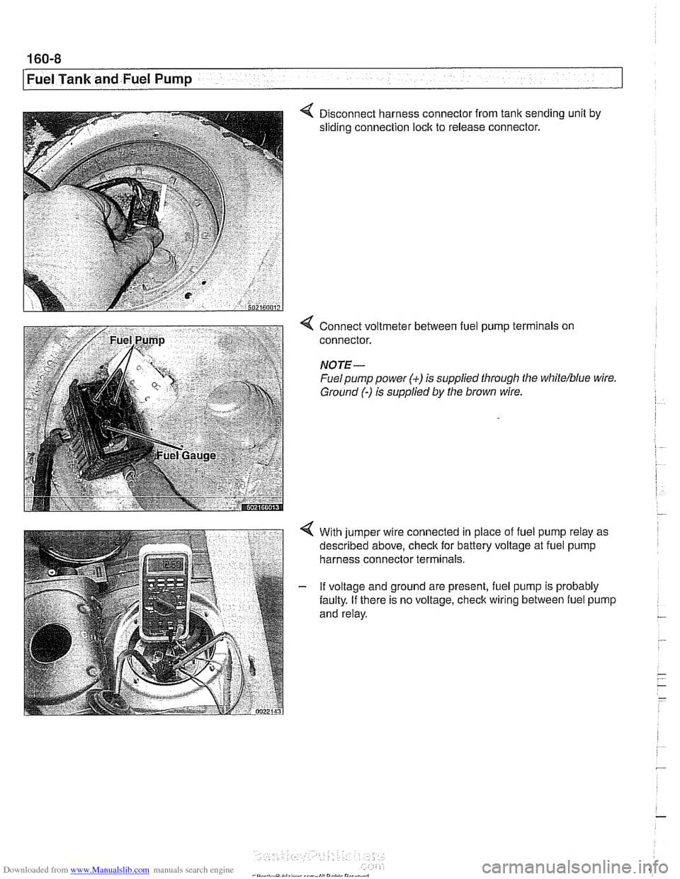
4 Disconnect harness connector from tank sending unit by
sliding connection lock to release connector.
Connect voltmeter between fuel pump terminals on
connector.
NOTE-
Fuel pump power (+) is supplied through the white/blue wire
Ground
(-) is supplied by the brown wire.
With jumper wire connected in place of fuel pump relay as
described above, check for battery voltage at fuel pump
harness connector terminals.
If voltage and ground are present, fuel pump is probably
faulty. If there is no voltage, check wiring between fuel pump
and relay.
Page 549 of 1002
Downloaded from www.Manualslib.com manuals search engine
21 0-7
Clutch
- Remove brake fluid reservoir cap. Using a clean syringe.
remove brake fluid from reservoir to below level of clutch
hydraulic supply hose.
- Detach clutch hydraulic supply hose from brake fluid reser-
voir. Plug reservoir outlet and hose.
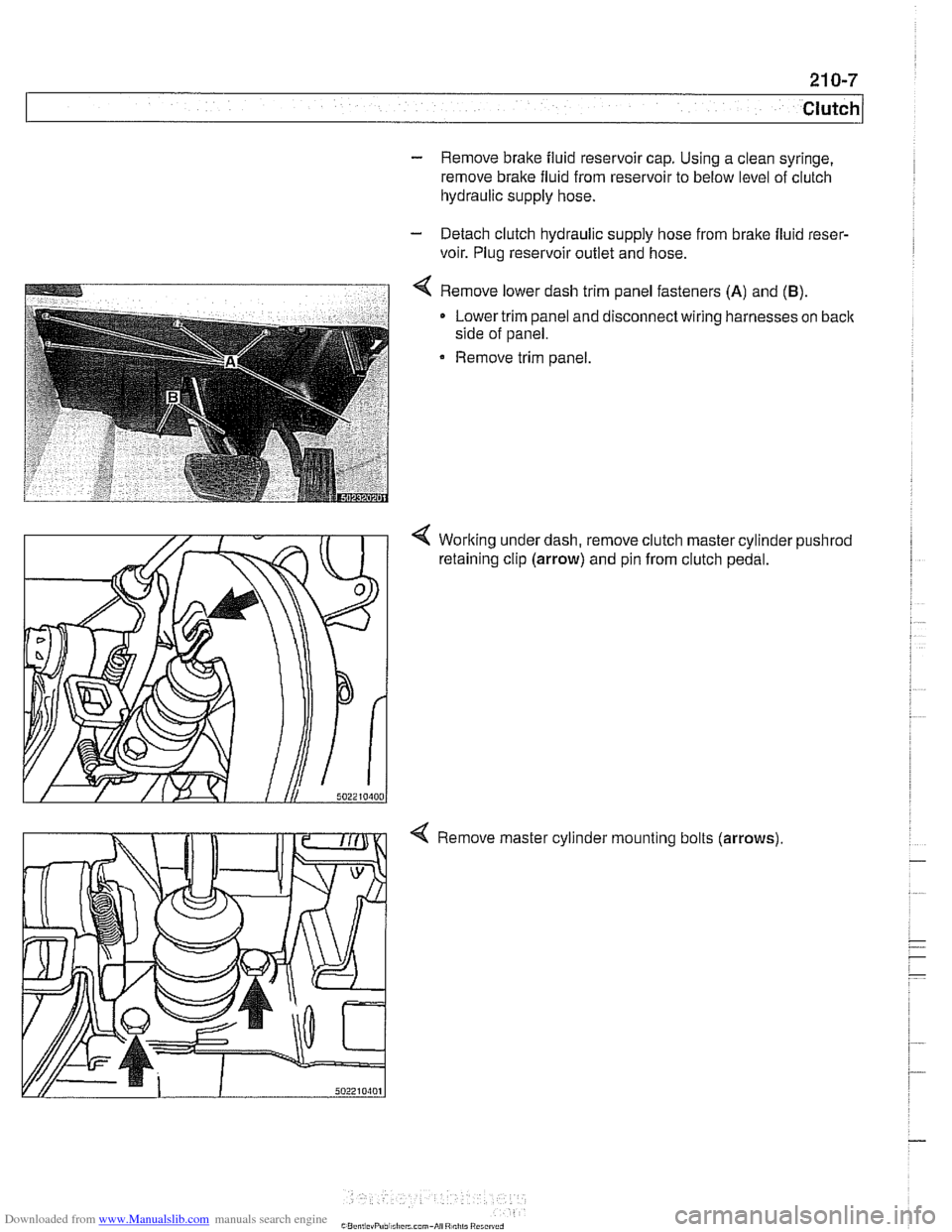
4 Remove lower dash trim panel fasteners (A) and (B).
Lower trim panel and disconnect wiring harnesses on back
side of panel.
Remove trim panel.
4 Working under dash, remove clutch master cylinder pushrod
retaining clip (arrow) and pin from clutch pedal.
4 Remove master cylinder mounting bolts (arrows)
Page 595 of 1002
Downloaded from www.Manualslib.com manuals search engine
Automatic ~ransmissionl
II I
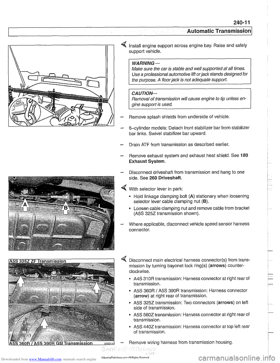
4 Install engine support across engine bay. Raise and safely
support vehicle.
Make sure the car is stable and
we1 supported at all times.
Use a professional automotive lift
orjaclc stands designed for
CAUTIOI\C
Removal of transmission will cause engine to tip unless en-
gine support is used.
- Remove splash shields from underside of vehicle.
- &cylinder models: Detach front stabilizer bar from stabilizer
bar
links. Swivel stabilizer bar upward.
- Drain ATF from transmission as described earlier.
- Remove exhaust system and exhaust heat shield. See 180
Exhaust System.
- Disconnect driveshaft from transmission and hang to one
side. See
260 Driveshaft.
4 With selector lever in park:
Hold
linkage clamping bolt (A) stationary when loosening
selector lever cable clamping nut
(6).
- Loosen cable clamping nut and remove cable from bracket
(ASS
3252 transmission shown).
- Where applicable, disconnect vehicle speed sensor harness
connector.
4 Disconnect main electrical harness connector(s) from trans-
mission by turning bayonet lock
ring(s) (arrows) counter-
clocltwise.
A4S
310R transmission: Harness connector at right rear of
transmission.
ASS
360R / ASS 390R transmission: Harness connector
(arrow) at right rear of transmission.
ASS 3252 transmission: Two connectors (arrows) on left
side of transmission.
ASS 5602 transmission: Harness connector at right rear of
transmission.
- ASS 4402 transmission: Harness connector at top left rear
of transmission.
- Remove wiring harness from transmission housing
Page 614 of 1002
Downloaded from www.Manualslib.com manuals search engine
-.- .
/ Driveshaft Driveshaft, removing
CAUTION-
. Be sure the wheels are off the ground before removing the
driveshak Set the parl(ing brake before removing the
driveshaft.
Once the driveshaft has been removed, the vehicle can
roll regardless of whether the transmission is in gear or
not.
The driveshaft is mounted to the transmission and final
drive
with self-locliing nuts. These nuts are designed to
be used only once and should be replaced during reas-
sembly.
Remove complete exhaust system. See
180 Exhaust
System.
- Remove exhaust heat shields.
- Support transmission with transmission jack.
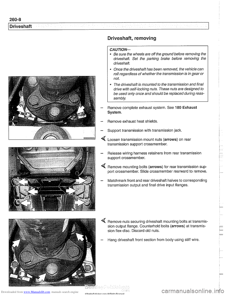
< Loosen transmission mount nuts (arrows) on real
transmission support crossmember.
- Release wiring harness retainers from rear transmission
support crossmember.
< Remove mounting bolts (arrows) for rear transmission sup-
port crossmember. Slide crossmember rearward to remove.
- Matchmark front and rear driveshaft halves to corresponding
transmission output and final drive input flanges.
4 Remove nuts securing driveshaft mounting bolts at transmis-
sion output flange. Counterhold bolts (arrows) at transmis-
sion flex-disc. Discard old nuts.
- Hang driveshaft front section from body using stiff wire.
Page 616 of 1002
Downloaded from www.Manualslib.com manuals search engine
260-1 0
/ Driveshaft
Driveshaft, installing
- Prepare CV joint for reinstallation:
Extend joint to limit.
Clean off old grease and fill with fresh grease
Install new seal.
- Bend driveshaft slightly at center universal joint to install
CAUTION-
Do not allow CVjoint seal to become displaced.
- Align matchmarlts on driveshaft to matchmarks on final drive
and transmission flanges.
- Fit constant velocity joint to final drive input flange. Alternate-
ly tighten two opposite nuts to draw constant velocity joint
evenly into the final drive input flange. Once seated, tighten
down remaining nuts.
I CAUTION-
I Do not reuse self-locking nuts. These nuts are designed to be /
I used onlv once. 1
- Insert bolts in front of driveshafl to transmission output
flange. Counterhold each bolt while tightening nut.
CAUTION-
. Do not reuse self-locking nuts. These nuts are designed to
be used only once.
Avoid stressing the flex-disc when torquing the bolts.
Do this by counterholding the bolts and turning the nuts
on the flange side.
- Position center support bearing and install mounting nuts.
Use new self-locking nuts.
- Install heat shields.
- Install rear transmission support crossmember.
- Install exhaust system. See 180 Exhaust System.
Reconnect oxygen sensor wiring harnesses and reattach
wiring harness retainers to rear transmission support
crossrnernber.
Page 669 of 1002
Downloaded from www.Manualslib.com manuals search engine
Steering and Wheel ~li~nrnentl
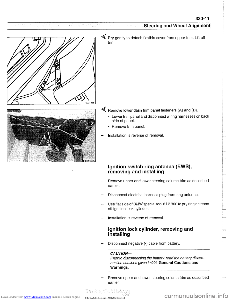
q Pry gently to detach flexible cover from upper trim. Lift off
trim.
< Remove lower dash trim panel fasteners (A) and (B).
Lower trim panel and disconnect wiring harnesses on back
side of panel.
Remove trim panel.
- Installation is reverse of removal.
Ignition switch ring antenna (EWS),
removing and installing
- Remove upper and lower steering column trim as described
earlier.
- Disconnect electrical harness plug from ring antenna.
- Use flat side of BMW special tool 61 3 300 to pry ring antenna
off ignition lock cylinder.
- Installation is reverse of removal.
lgnition lock cylinder, removing and
installing
- Disconnect negative (-) cable from battery.
CAUTION-
Prior to disconnecting the battery, read the battery discon-
nection cautions given
in 001 General Cautions and
Warnings.
- Remove upper and lower steering column trim as described
earlier.
Page 673 of 1002
Downloaded from www.Manualslib.com manuals search engine
320-1 5
Steering and Wheel ~li~nmentl
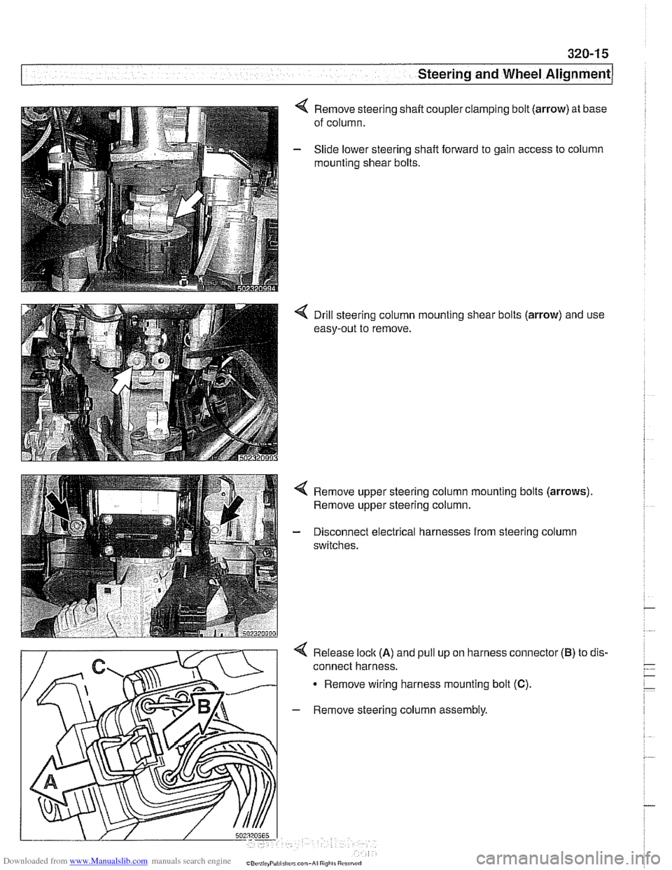
Remove steering shaft coupler clamping bolt (arrow) at base
of column.
Slide lower steering shaft forward to gain access to column
mounting shear bolts.
< Drill steering column mounting shear bolts (arrow) and use
easy-out to remove.
Remove upper steering column mounting bolts
(arrows).
Remove upper steering column.
Disconnect electrical harnesses from steering column
switches.
4 Release lock (A) and pull up on harness connector
connect harness.
Remove wiring harness mounting bolt
(C).
- Remove steering column assembly.
(B) to dis.
Page 674 of 1002
Downloaded from www.Manualslib.com manuals search engine
I Steering and Wheel Alignment
- Installation is reverse of removal, noting the following:
Replace shear bolts at steering column mounting bracket.
Tighten until bolt heads shear off.
Make sure
interlock cable snaps into place.
When installing column top trim panel, replace expansion
nut for trim retaining screw.
NOTE-
The steering angle sensor must be coded using a BMW scan
tool if it has been replaced.
A steering angle offset check
must then be carried out using the same
BMW scan tool.
CAUTION-
Check steering system for freedom of movement through en-
tire steering column
adiustment range.
Tightening torques Steering shaft coupler
to steering shaft 25 Nm (18 ft-lb)
(replace bolt)
Steering column to body
22 Nm (16 ft-lb)
Steering column adjustment motors,
removing and installing
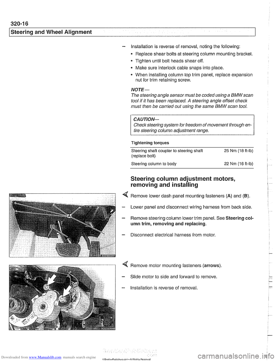
Remove lower dash panel mounting fasteners (A) and (B).
- Lower panel and disconnect wiring harness from back side.
- Remove steering column lower trim panel. See Steering col-
umn trim, removing and replacing.
- Disconnect electrical harness from motor.
Remove motor mounting fasteners (arrows)
Slide motor to side and forward to remove.
Installation is reverse of removal.