Tcm BMW 525i 2001 E39 Workshop Manual
[x] Cancel search | Manufacturer: BMW, Model Year: 2001, Model line: 525i, Model: BMW 525i 2001 E39Pages: 1002
Page 589 of 1002

Downloaded from www.Manualslib.com manuals search engine
- .- -
Automatic Transmission
Electronics are used to control the operation of these auto-
matic transmissions. Steptronic transmission functions are
also programmed into the transmission control module
(TCM). The TCM monitors transmission operation for faults
and alerts the driver by illuminating the transmission fault indi-
cator on the instrument panel. Diagnostic trouble codes
(DTCs) stored in the TCM may be downloaded and interpret-
ed by trained technicians using special BMW diagnostic
equipment.
Some minor automatic transmission problems can be cor-
rected by changing the automatic transmission fluid (ATF)
and filter. Begin by checking ATF level and condition.
Checlc
to see if the fluid is dirty or has a burned odor indicating over-
heated fluid. The burned odor may be the results of burned
discs in theclutch paclts. The friction material from the burned
disc can clog valve body passages.
NOTE-
The E39 automatic transmission is not equipped with a dip-
stick.
Checking the ATF level must be done while monitoring
the ATF temperature with the engine idling. The
BMW dealer
is equipped with the special equipment to make this check.
Page 605 of 1002

Downloaded from www.Manualslib.com manuals search engine
250-7
Gearshift ~inka~el
Automatic shiftlock, checking function (automatic transmission)
The automatic shiftlock uses an electric solenoid to lock the
selector lever in Park or Neutral. Depressing the foot bralte
with the ignition on energizes the solenoid, allowing the lever
to be moved into a drive gear. The solenoid is energized only
when the engine speed is below 2,500 rpm and the vehicle
speed is below
3 mph (5 kph). The solenoid is mounted in the
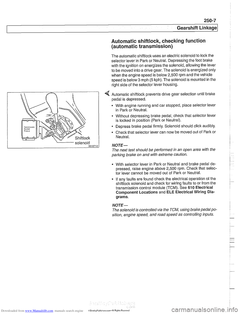
right side of the selector lever housing.
... nir r
Shiftlock
4 Automatic shiftlock prevents drive gear selection until brake
pedal is depressed.
With engine running and car stopped, place selector lever
in Park or Neutral.
Without depressing bralte pedal, check that selector lever
is
loclted in position (Parlt or Neutral).
Depress brake pedal firmly. Solenoid should click audibly.
Check that selector lever can now be moved out of
Parlt or
Neutral.
parking
brake on and with extreme caution.
solenoid
0012713
With selector
lever in Park or Neutral and bralte pedal de-
pressed, raise engine above 2,500
rpm. Check that selec-
tor lever cannot be moved out of Park or Neutral.
If any faults are found check the electrical operation of the
shiftloclt solenoid and checlt for wiring faults to or from the
transmission control module (TCM). See
610 Electrical
Component Locations and ELE Electrical Wiring
Dia-
grams.
NOTE-
NOTE-
The solenoidis controlled via the TCM, using brake pedalpo-
sition, engine speed, and road speed as controlling inputs.
The
next test should be performed in an open area with the
Page 962 of 1002

Downloaded from www.Manualslib.com manuals search engine
OED-2
On-Board Diagnostics
Specialized OED II scan tool equipment is needed to access
the fault memory and
OED I1 data.
The extra hardware needed to operate the OED
I1 system
consists mainly of the following:
* Additional oxygen sensors downstream of the catalytic
converters.
Fuel tank pressure sensor and device to pressurize
fuel
storage system.
Several engine and performance monitoring devices
Standardized 16-pin
OED II connector under the
dashboard.
Upgraded components for the federally required reliability
mandate.
Malfunction indicator light (MIL)
OED II software illuminates the malfunction indicator light
(MIL) when emission levels exceed 1.5 times Federal
standards.
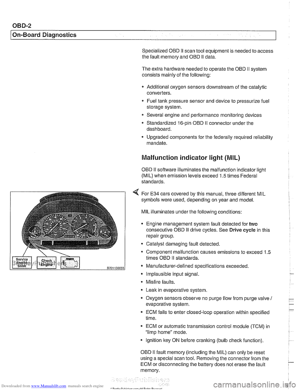
4 For E34 cars covered by this manual, three different MIL
symbols were used, depending on year and model.
MIL illuminates under the following conditions:
Engine management system fault detected for
two
consecutive OED iI drive cycles. See Drive cycle in this
repair group.
- Catalyst damaging fault detected.
Component malfunction causes emissions to exceed 1.5
times OED
II standards.
Manufacturer-defined specifications exceeded. Implausible input signal.
Misfire
faults.
Leak in evaporative system,
Oxygen sensors observe no purge
flow from purge valve 1
evaporative system.
ECM fails to enter closed-loop operation within specified
time.
ECM or automatic transmission control
module (TCM) in
"limp home" mode.
ignition key ON before cranking (bulb
check function).
OED
II fault memory (including the MIL) can only be reset
using a special scan tool. Removing the connector from the
ECM or disconnecting the battery does not erase the fault
memory.
Page 1000 of 1002

Downloaded from www.Manualslib.com manuals search engine
Steering description 300-10
liuid see Maintenance
gearbox
320-25
idler arm 320-30
lock 320-12
pitman arm 320-28 power steering pump 320-17
rack & pinion 320-19
steering column 320-10 motors 320-16
removinglinstalling 320-14
trim 320-10
steerino wheei 320-7 tie rods-
6-cvlinder, reelacinq 320-22
V- center tie' rod, replacing 320-32
variations 310-5
Steering box
see Steering, gearbox
Steering column switches
see Switches
Steering column
see Steering
Steering lock
see Steering
Steering
wheei switches
see Switches
Stepper motor
see
AIC
Steptronic transmission
see Gearshift
Strut see Front suspension
see also Rear suspension
Subframe see Rear suspension
Sunroof initializing
540-2
adiustinq 540-5 . . cornponents, removingiinstailing
540-9
emergency closing 540-4
Suspension, front
see Front suspension
see also
Aluminum suspension
cornponents
Suspension, rear
see Rear suspension
see also Aluminum suspension
cornponents
Swing arm
see Rear suspension, suspension
arms
Switches
ASCIDSC 612-12 back-ue
manual transmission 230-8
automatic transmission, see
Automatic transmission, range
switch
center console switches
612-11
central ioci(ing 612-1 1
hazard 612-1 I headlight 612-9
ignition cylinder 320-1 1. 612-6
outside mirror 612-11
pedal cluster switches 612-8 seat heater 612.12
steering column positioning 612-7
steering column switches 612-6 steering wheel switches 612-2
turn signaliheadlight dimmer 612-6
window 612-1 1
wipers 612-6
Tailgate
412-6 emergency release 400-4,412-6,
515-21
taiigatelrear window
loclring 515-14 see also Trunldtaiioate ioclr - see also Central ioclcing
Taillights
see Lights
Tape player
650-3
TCM (transmission control module)
see Automatic transmission
Tension strut
see Front suspension
Thermostat see Cooling system
see also Electrically heated
thermostat
Throttie body
see 130 under appropriate
fuel injection system
Throttie
cable
130-38
Throttie position sensor
see 130 under appropriate luel
injection system
Throw-out bearing
see Clutch, mechanical
Thrust arm
see Front suspension
Tie rod
see Steering
Tightening fasteners
010-8
Tilt sensor 515-24
Timing chain
see
Camshaft timing chain
Tire, changing
010-18
Tires
300-1 1
see also Maintenance
Toe
320-34
Tools
010-13