Troubleshoot BMW 525i 2001 E39 Workshop Manual
[x] Cancel search | Manufacturer: BMW, Model Year: 2001, Model line: 525i, Model: BMW 525i 2001 E39Pages: 1002
Page 13 of 1002
Downloaded from www.Manualslib.com manuals search engine
General
0 GENERAL, MAINTENANCE covers general vehicle infor-
mation
(010 General) as well as the recommended mainte-
nance schedules and service procedures to perform BMW
scheduled maintenance
work (020 Maintenance).
The next seven sections
(1 through 7) are repair based and
organized by three digit repair groups. Most major sections
begin with a GENERAL repair group,
e.g. 100 Engine-Gen-
eral. These "00 (double zero) groups contain descriptive the-
ory of operation and system troubleshooting information. The
remainder of the repair groups within a section contain the
service and repair information. The last two sections contain
detailed electrical wiring schematics and OBD
II scan tool and
diagnostic information.
Warnings, cautions and notes
Throughout this manual are many passages with the head-
ings WARNING, CAUTION, or NOTE. These very important
headings have different meanings.
WARNING-
The text under this heading warns of unsafe practices that
are very
likely to cause injury, either by direct threat to the per-
son(~) performing the work
orby increasedrisl( of accident or
mechanical failure while
drivinq.
CAUTION-
A CAUTION calls attention to importantprecautions to be ob-
senfed during the repair work that will help prevent acciden-
tally damaging the car or its parts.
NOTE-
A NOTE contains helpful information, tips that will help in do-
ing a betterjob and completing it more easily.
Please read every WARNING, CAUTION, AND NOTE in
001
General Warnings and Cautions and as they appear in re-
pair procedures. They are very important. Read them before
you begin any maintenance or repair job.
Page 27 of 1002
Downloaded from www.Manualslib.com manuals search engine
.
General
Torque wrench
A torque wrench is used to precisely tighten threaded fasten-
ers to a predetermined value. Many of the repair procedures
in this manual include BMW-specified torque values
in New-
ton-meters (Nm) and the equivalent values in foot-pounds
(ft-
Ib).
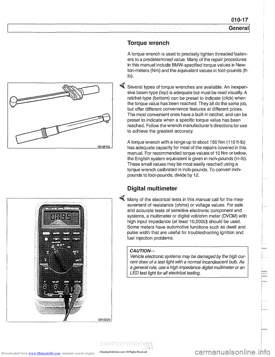
4 Several types of torque wrenches are available. An inexpen-
sive beam-type (top) is adequate but must be read visually. A
ratchet-type (bottom) can be preset to indicate (click) when
the torque value has been reached. They all do the same job,
but offer different convenience features at different prices.
The most convenient ones have a built-in ratchet, and can be
preset to indicate when a specific torque value has been
reached. Follow the wrench manufacturer's directions
for use
to achieve the greatest accuracy.
A torque wrench with a range up to about 150 Nm (1 10 ft-lb) BOIBFNG has adequate capacity for most of the repairs covered in this
manual. For recommended torque values of
10 Nm orbelow,
the English system equivalent is given in inch-pounds (in-lb).
These small values may be most easily reached using a
torque wrench calibrated in inch-pounds. To convert
inch-
pounds to foot-pounds, divide by 12.
Digital multimeter
4 Many of the electrical tests in this manual call for the mea-
surement of resistance (ohms) or voltage values. For safe
and accurate tests of sensitive electronic component and
systems, a multimeter or digital
volt/ohm meter (DVOM) with
high input impedance (at least
10,000Sr) should be used.
Some meters have automotive functions such as dwell and
pulse width that are useful for troubleshooting ignition and
fuel injection problems.
CAUTIOI\C
Vehicle electronic systems may be damaged by the high cur-
rent draw of a test light with a normal incandescent bulb. As
a general rule, use a high impedance digital multimeter or an
LED test light for all electrical testing.
Page 67 of 1002
Downloaded from www.Manualslib.com manuals search engine
100 Engine-General
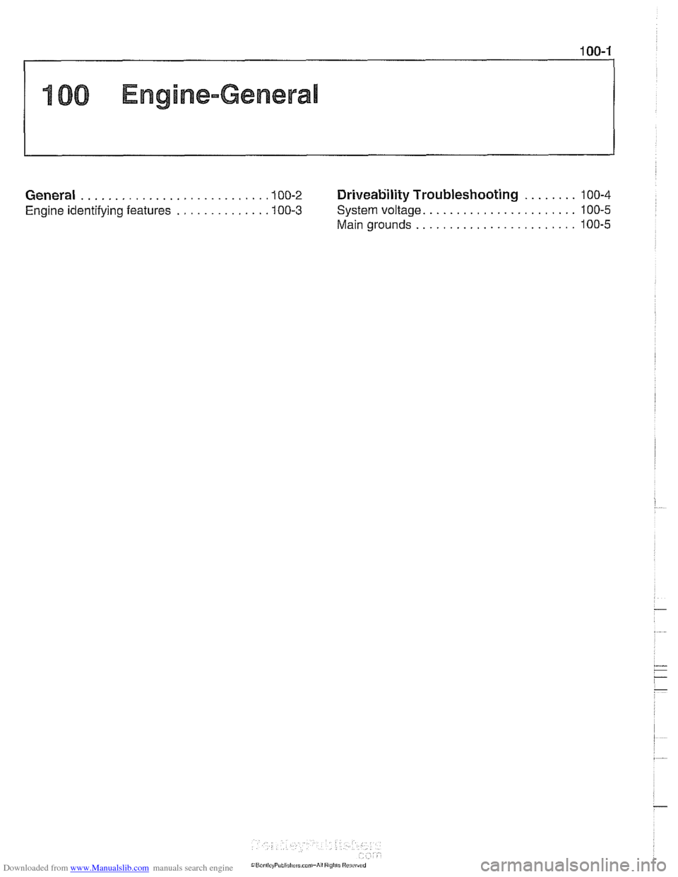
........ General ........................... .I0 0.2 Driveability Troubleshooting 100-4
....................... Engine identifying features ............. .I0 0.3 System voltage 100-5
........................ Main grounds 100-5
Page 68 of 1002
Downloaded from www.Manualslib.com manuals search engine
Engine-General
This section covers system descriptions and general informa-
tion on engines and engine management systems. Also cov-
ered is basic engine troubleshooting.
For specific repair procedures, refer to the appropriate repair
group:
110 Engine Removal and Installation
0 113 Cylinder Head Removal and Installation
116 Cylinder Head and Valvetrain
0 117 Camshaft Timing Chain
119 Lubrication System
120 Ignition System
130 Fuel Injection
0 170 Radiator and Cooling System
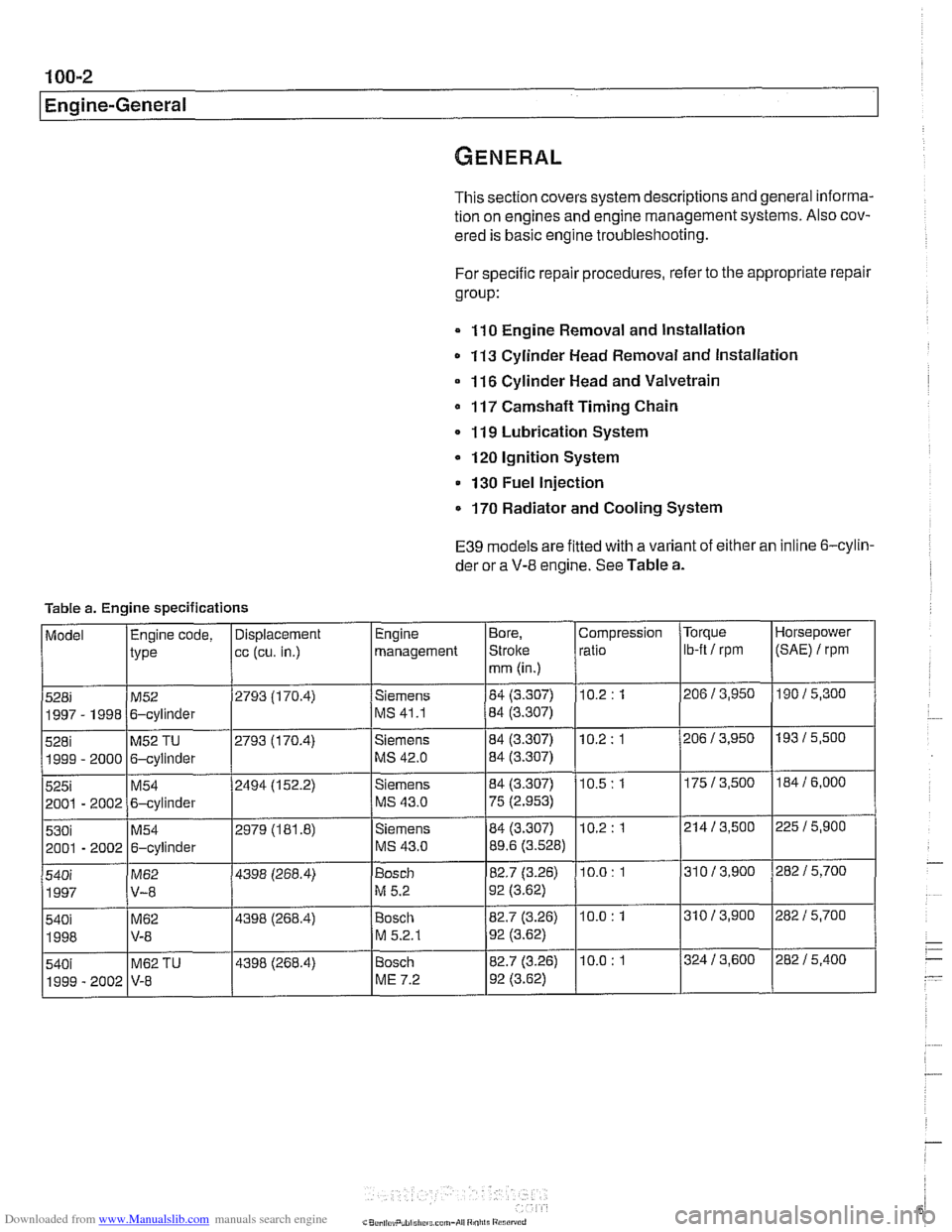
E39 models are fitted with a variant of either an inline 6-cylin-
der or a
V-8 engine. See Table a.
Table a. Engine specifications
Page 71 of 1002
Downloaded from www.Manualslib.com manuals search engine
Two common causes of driveability problems are incorrect
system voltage and bad grounds.
System voltage
Digital motor electronics (DME) requires that the system (bat-
tery) voltage be maintained within a narrow range of DC volt-
age.
DC voltage levels beyond or below the operating range,
or any
AIC voltage in the electrical system can cause havoc.
When troubleshooting an illuminated MIL, make sure the bat-
tery is fully charged and capable of delivering all its power to
the electrical system. An undercharged battery can amplify
AIC alternator output ripple.
To
make a quick check of the battery charge, measure the
voltage across the battery terminals with all cables attached
and the ignition off.
Afully charged battery will measure 12.6
volts or slightly more, compared to 12.1 5 volts for a battery
with a 25% charge.
The DME system operates at low voltage and current levels,
making it sensitive to small increases in resistance. The elec-
trical system is routinely subjected to corrosion, vibration and
wear, so faults or corrosion in the wiring harness and connec-
tors are not uncommon. Check the battery terminals
forcorro-
sion or loose cable connections. See 121 Battery, Starter,
Alternator for additional information.
If a battery cable connection has no
v~sible faults but is still
suspect, measure the voltage drop across the connection. A
large drop indicates excessive resistance, meaning that the
connection is corroded, dirty, or damaged. Clean or repairthe
connection and retest.
NOTE-
For instructions on conducting a voltage drop test and other
general electrical troubleshooting information, see
600 Elec-
trical System-General.
Visually inspect all wiring, connectors, switches and fuses in
the system. Loose or damaged connectors can cause inter-
mittent problems, especially the small terminals in the ECM
connectors. Disconnect the wiring harness connectors to
check for corrosion, and use electrical cleaning spray to re-
move contaminants.
Main grounds
Good grounds are critical to proper DME operation. If a
ground connection has no visible faults but is still suspect.
measure the voltage drop across the connection. A large volt-
age drop means high resistance. Clean or repair the connec-
tion and retest.
LBuntr.yP~sbhnllcn.can#-AII A,~iltl Rcsrwsd
Page 271 of 1002
Downloaded from www.Manualslib.com manuals search engine
Camshaft Timing Chain
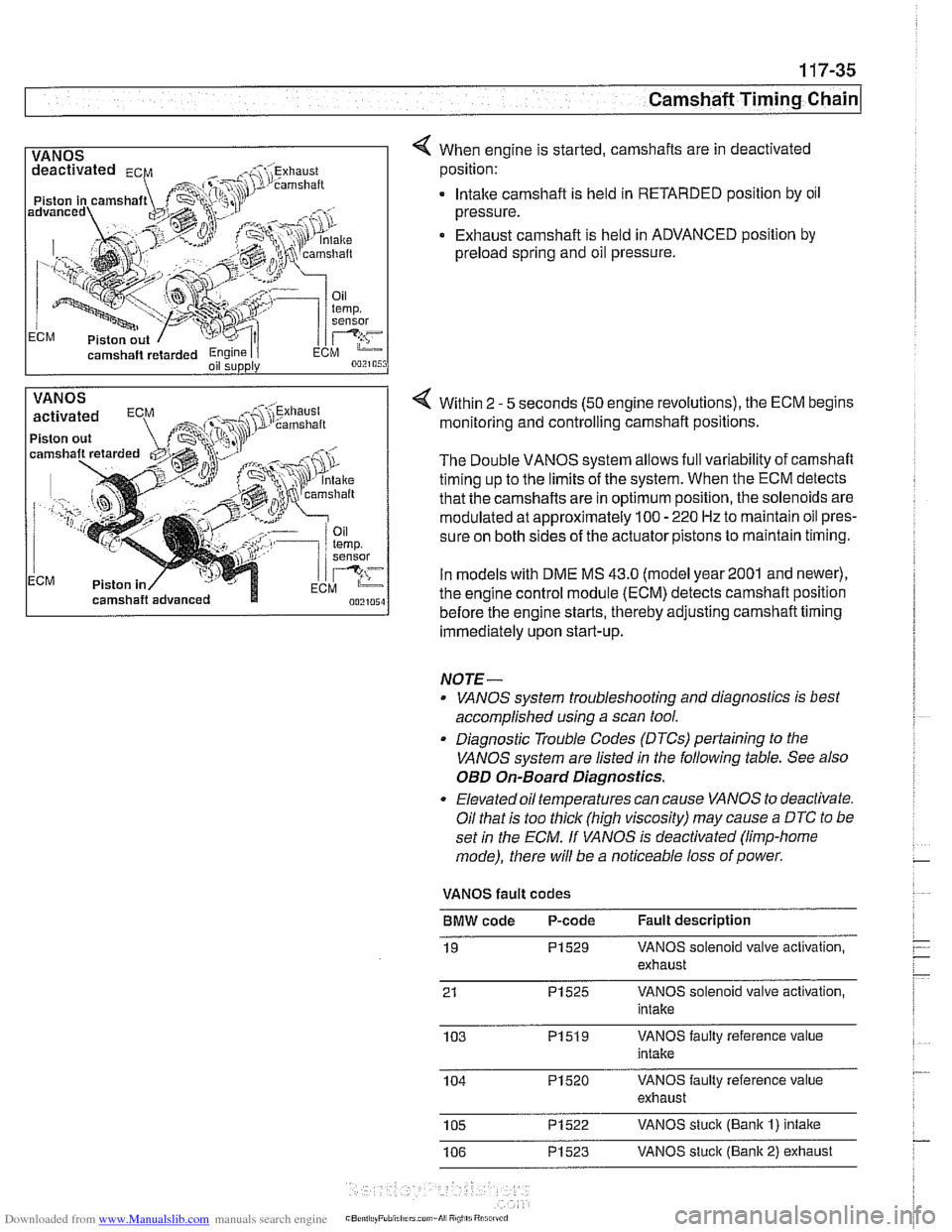
1 VANOS I 4 When engine is started, camshafts are in deactivated
camshaft
retarded Engine I i oil supply
position:
. lntalte camshaft is held in RETARDED position by oil
pressure.
Exhaust camshaft is held in ADVANCED position by
preload spring and oil pressure.
VANOS
Piston out
ECM Piston in Within 2
- 5
seconds (50 engine revolutions), the ECM begins
monitoring and controlling camshaft positions.
The Double VANOS system allows full variability of camshaft
timing up to the limits of the system. When the ECM detects
that the camshafts are in optimum position, the solenoids are
modulated at approximately 100
- 220 Hz to maintain oil pres-
sure on both sides of the actuator pistons to maintain timing.
In models with DME
MS 43.0 (model year2001 and newer),
the engine control module (ECM) detects camshaft position
before the engine starts, thereby adjusting camshaft timing
immediately upon start-up.
NOTE-
. VANOS system troubleshooting and diagnostics is best
accomplished using a scan tool.
. Diagnostic Trouble Codes (DTCs) pertaining to the
VANOS system are listed
in the following table. See also
OED On-Board Diagnostics.
Elevated oil temperatures can cause VANOS to deactivate.
Oil that is too thick (high viscosity) may cause
a DTC to be
set
in the ECM. If VANOS is deactivated (limp-home
mode), there will be a noticeable loss of power.
VANOS fault codes
BMW code P-code Fault description
19
PI529 VANOS solenoid valve activation,
exhaust
21
PI525 VANOS solenoid valve activation,
intake
103
PI519 VANOS faulty reference value
intake
104
PI520 VANOS faulty reference value
exhaust
105
PI522 VANOS stuck (Bank I) intake
106
PI523 VANOS stuck (Bank 2) exhaust
Page 321 of 1002
Downloaded from www.Manualslib.com manuals search engine
11 9 Lubrication System
General ............................ 11 9-2
Special tools
......................... 11 9-2
..................... Engine lubrication 11 9-3
Troubleshooting .................... 11 9-3
................. Oil pressure. checking 11 9-4
...... Oil pressure warning system. testing 11 9-5
Crankshaft Rear Main Seal ......... .I1 9-6
Crankshaft rear main seal.
replacing (6-cylinder)
.................. 11 9-6
Crankshaft rear main seal. replacing (V-8)
. . 11 9-8
Engine Oil Pan .................... .I1 9-10
Oil pan. removing and
................. installing (6-cylinder) .I1 9-10
Lower oil pan. removing and
installing (V-8)
....................... 1 19-1 3
Upper oil pan. removing and
installing (V-8)
....................... 11 9-1 5
.......... Component Replacement 11 9-20
Oil pressure warning switch. replacing
.................. (6-cylinder and V-8) 11 9-20
Oil level warning switch. replacing
.................. (6-cylinder and V-8) 11 9-21
Oil pump. removing and
................. installing (6-cylinder) 11 9-22
Oil pump. removing and installing (V-8)
. . 11 9-24
..... Oil pressure relief valve (6-cylinder) 119-26
.......... Oil pressure
relief valve (V-8) 11 9-27
Page 322 of 1002
Downloaded from www.Manualslib.com manuals search engine
11 9-2
Lubrication System
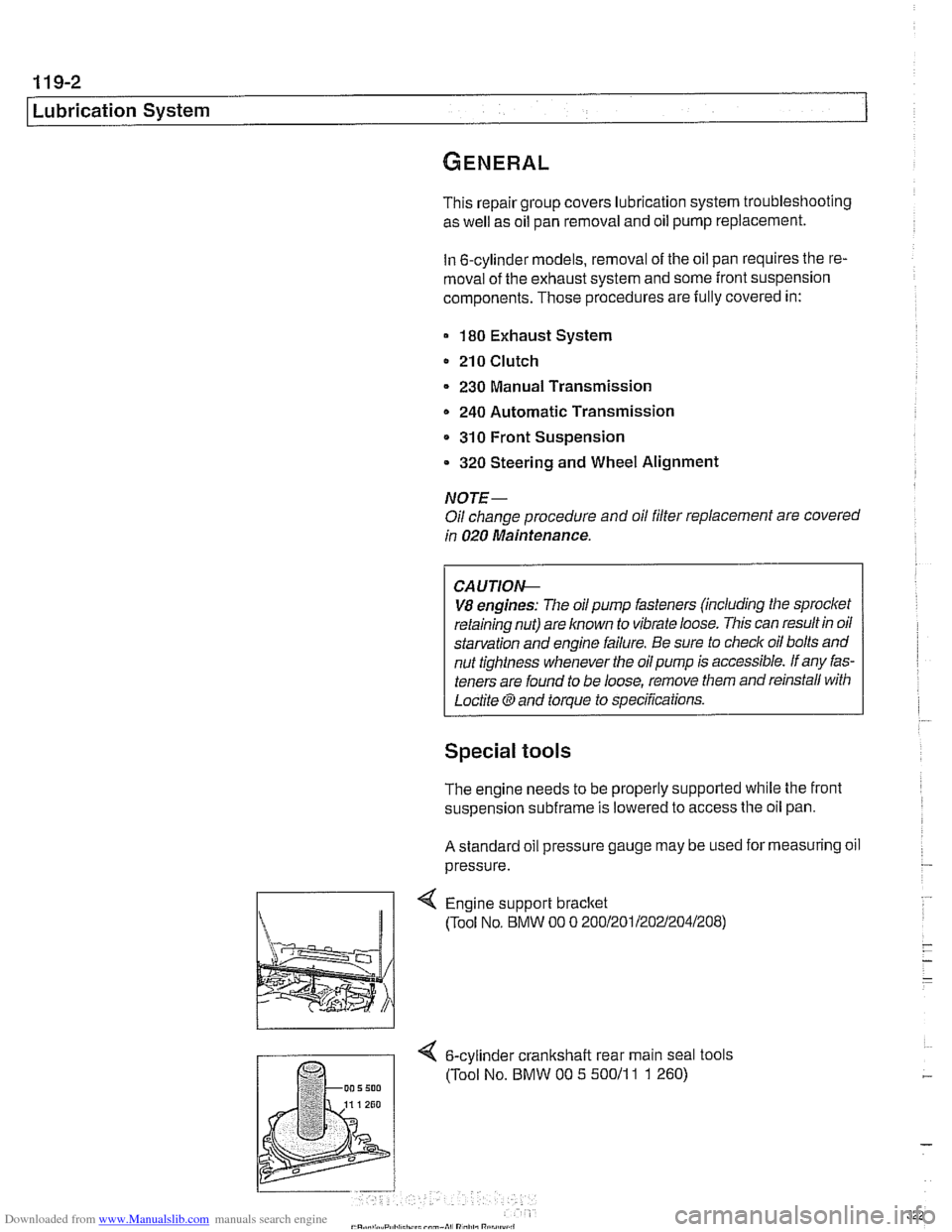
This repair group covers lubrication system troubleshooting
as well as oil pan removal and oil pump replacement.
In 6-cylinder models, removal of the oil pan requires the re-
moval of the exhaust system and some front suspension
components. Those procedures are fully covered in:
180 Exhaust System
210 Clutch
230 Manual Transmission
0 240 Automatic Transmission
310 Front Suspension
320 Steering and Wheel Alignment
NOTE-
Oil change procedure and oil filter replacement are covered
in
020 Maintenance.
CAUTIOG
V8 engines: The oil pump fasteners (including the sprocket
retaining nut) are known to vibrate loose. This can result in oil
starvation and engine failure. Be sure to check oil bolts and
nut tightness whenever the
oilpump is accessible. If any fas-
teners are found to be loose, remove them and reinstall with
Loctite
Band torque to specifications.
Special tools
The engine needs to be properly supported while the front
suspension
subframe is lowered to access the oil pan.
A standard oil pressure gauge may be used for measuring oil
pressure.
Engine support bracket
(Tool No, BMW 00 0 20012011202~2041208)
4 6-cylinder crankshalt rear main seal tools
(Tool No. BMW 00 5 50011
1 1 260)
Page 349 of 1002
Downloaded from www.Manualslib.com manuals search engine
120 lgnition System
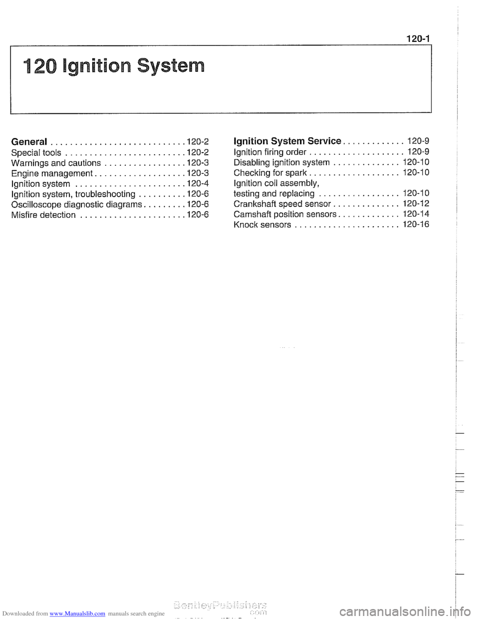
...................... General
Special tools ...................
Warnings and cautions ...........
Engine management .............
................. lgnition system
Ignition system. troubleshooting
....
... Oscilloscope diagnostic diagrams
................ Misfire detection
............. Ignition System Service 120-9
.................... Ignition firing order 120-9
.............. Disabling ignition system 120-10
................... Checking for spark 120-1 0
lgnition coil assembly.
................. testing and replacing 120-1 0
.............. Crankshaftspeedsensor 120-12
............. Camshaft position sensors 120-1 4
...................... Knocksensors 120-16
Page 350 of 1002
Downloaded from www.Manualslib.com manuals search engine
Ignition System
This repair group covers component troubleshooting and re-
placement information for the ignition system.
When diagnosing engine management problems, including
on-board diagnostics (OBD
11) fault code analysis, also refer
to these repair groups:
* 130 Fuel Injection
* ELE Electrical Wiring Diagrams
OED On-Board Diagnostics
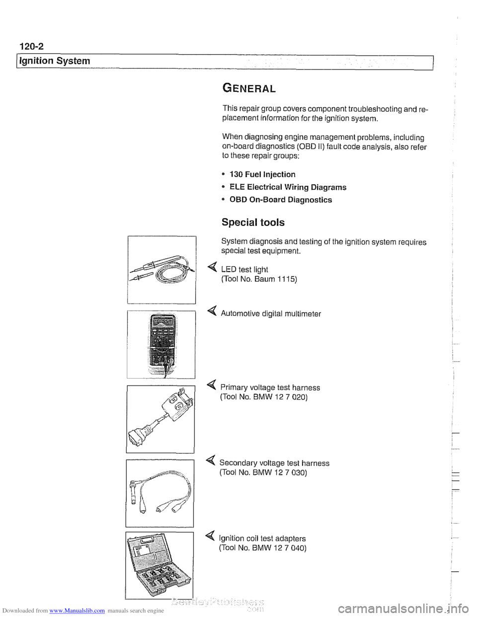
Special tools
System diagnosis and testing of the ignition system requires
special test equipment.
4 LED test light
(Tool No. Baum
1 1 15)
4 Automotive digital multimeter
4 Primary voltage test harness
(Tool No. BMW 12
7 020)
-
4 Secondary voltage test harness
(Tool No. BMW 12
7 030)