ESP BMW 525I 2002 E39 Central Body Electronics ZKE Manual
[x] Cancel search | Manufacturer: BMW, Model Year: 2002, Model line: 525I, Model: BMW 525I 2002 E39Pages: 80, PDF Size: 4.14 MB
Page 60 of 80

Mirror
Principle of Operation
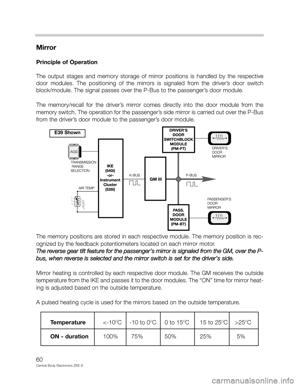
The output stages and memory storage of mirror positions is handled by the respective
door modules. The positioning of the mirrors is signaled from the driver’s door switch
block/module. The signal passes over the P-Bus to the passenger’s door module.
The memory/recall for the driver’s mirror comes directly into the door module from the
memory switch. The operation for the passenger’s side mirror is carried out over the P-Bus
from the driver’s door module to the passenger’s door module.
The memory positions are stored in each respective module. The memory position is rec-
ognized by the feedback potentiometers located on each mirror motor.
The reverse gear tilt feature for the passenger’s mirror is signaled from the GM, over the P-
bus, when reverse is selected and the mirror switch is set for the driver’s side.
Mirror heating is controlled by each respective door module. The GM receives the outside
temperature from the IKE and passes it to the door modules. The “ON” time for mirror heat-
ing is adjusted based on the outside temperature.
A pulsed heating cycle is used for the mirrors based on the outside temperature.
60
Central Body Electronics ZKE III
Temperature<-10OC -10 to 0OC 0 to 15OC 15 to 25OC >25OC
ON - duration 100% 75% 50% 25% 5%
E39 Shown
Page 62 of 80

Driver’s Seat (E38/E39)
Principle of Operation
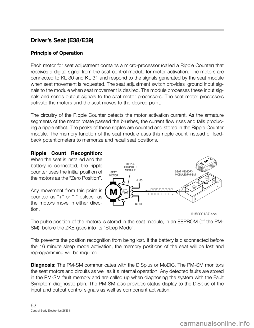
Each motor for seat adjustment contains a micro-processor (called a Ripple Counter) that
receives a digital signal from the seat control module for motor activation. The motors are
connected to KL 30 and KL 31 and respond to the signals generated by the seat module
when seat movement is requested. The seat adjustment switch provides ground input sig-
nals to the module when seat movement is desired. The module processes these input sig-
nals and sends output signals to the seat motor processors. The seat motor processors
activate the motors and the seat moves to the desired point.
The circuitry of the Ripple Counter detects the motor activation current. As the armature
segments of the motor rotate passed the brushes, the current flow rises and falls produc-
ing a ripple effect. The peaks of these ripples are counted and stored in the Ripple Counter
module. The memory function of the seat module uses this ripple count instead of feed-
back potentiometers to memorize and recall seat positions.
Ripple Count Recognition:
When the seat is installed and the
battery is connected, the ripple
counter uses the initial position of
the motors as the “Zero Position”.
Any movement from this point is
counted as “+” or “-” pulses as
the motors move in either direc-
tion.
The pulse position of the motors is stored in the seat module, in an EEPROM (of the PM-
SM), before the ZKE goes into its “Sleep Mode”.
This prevents the position recognition from being lost. If the battery is disconnected before
the 16 minute sleep mode activation, the memory positions of the seat will be lost and
reprogramming will be required.
Diagnosis: The PM-SM communicates with the DISplus or MoDiC. The PM-SM monitors
the seat motors and circuits as well as it's internal operation. Any detected faults are stored
in the PM-SM fault memory and are called up when diagnosing the system with the Fault
Symptom diagnostic plan. The PM-SM also provides status display to the DISplus of the
input and output control signals as well as component activation.
62
Central Body Electronics ZKE III
615200137.eps
Page 67 of 80

67
Central Body Electronics ZKE III
Seat Heating Operation (from 99 MY)
Principle of Operation
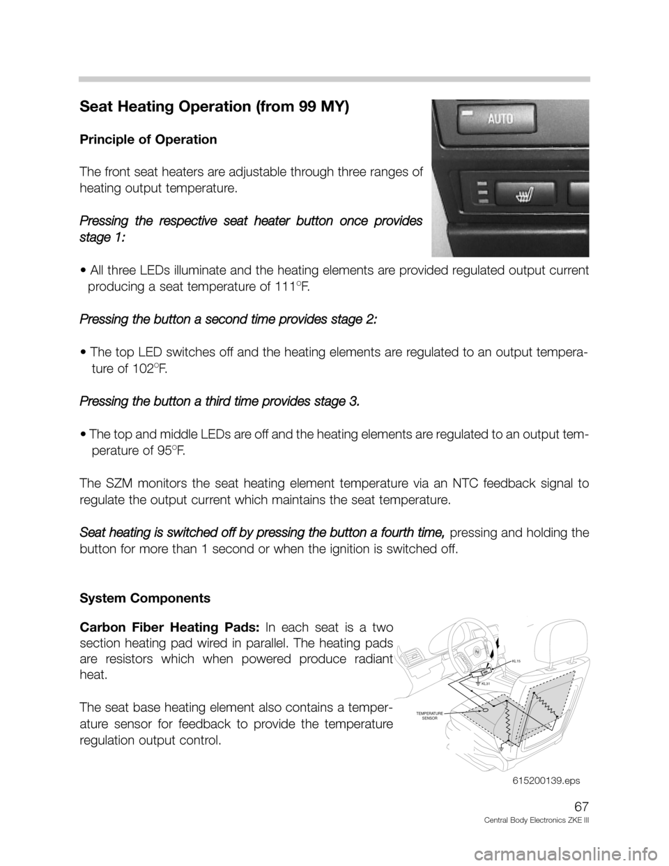
The front seat heaters are adjustable through three ranges of
heating output temperature.
Pressing the respective seat heater button once provides
stage 1:
• All three LEDs illuminate and the heating elements are provided regulated output current
producing a seat temperature of 111
OF.
Pressing the button a second time provides stage 2:
• The top LED switches off and the heating elements are regulated to an output tempera-
ture of 102
OF.
Pressing the button a third time provides stage 3.
• The top and middle LEDs are off and the heating elements are regulated to an output tem-
perature of 95
OF.
The SZM monitors the seat heating element temperature via an NTC feedback signal to
regulate the output current which maintains the seat temperature.
Seat heating is switched off by pressing the button a fourth time,
pressing and holding the
button for more than 1 second or when the ignition is switched off.
System Components
Carbon Fiber Heating Pads:In each seat is a two
section heating pad wired in parallel. The heating pads
are resistors which when powered produce radiant
heat.
The seat base heating element also contains a temper-
ature sensor for feedback to provide the temperature
regulation output control.
KL31
KL15
TEMPERATURE
SENSOR
615200139.eps
Page 68 of 80

68
Central Body Electronics ZKE III
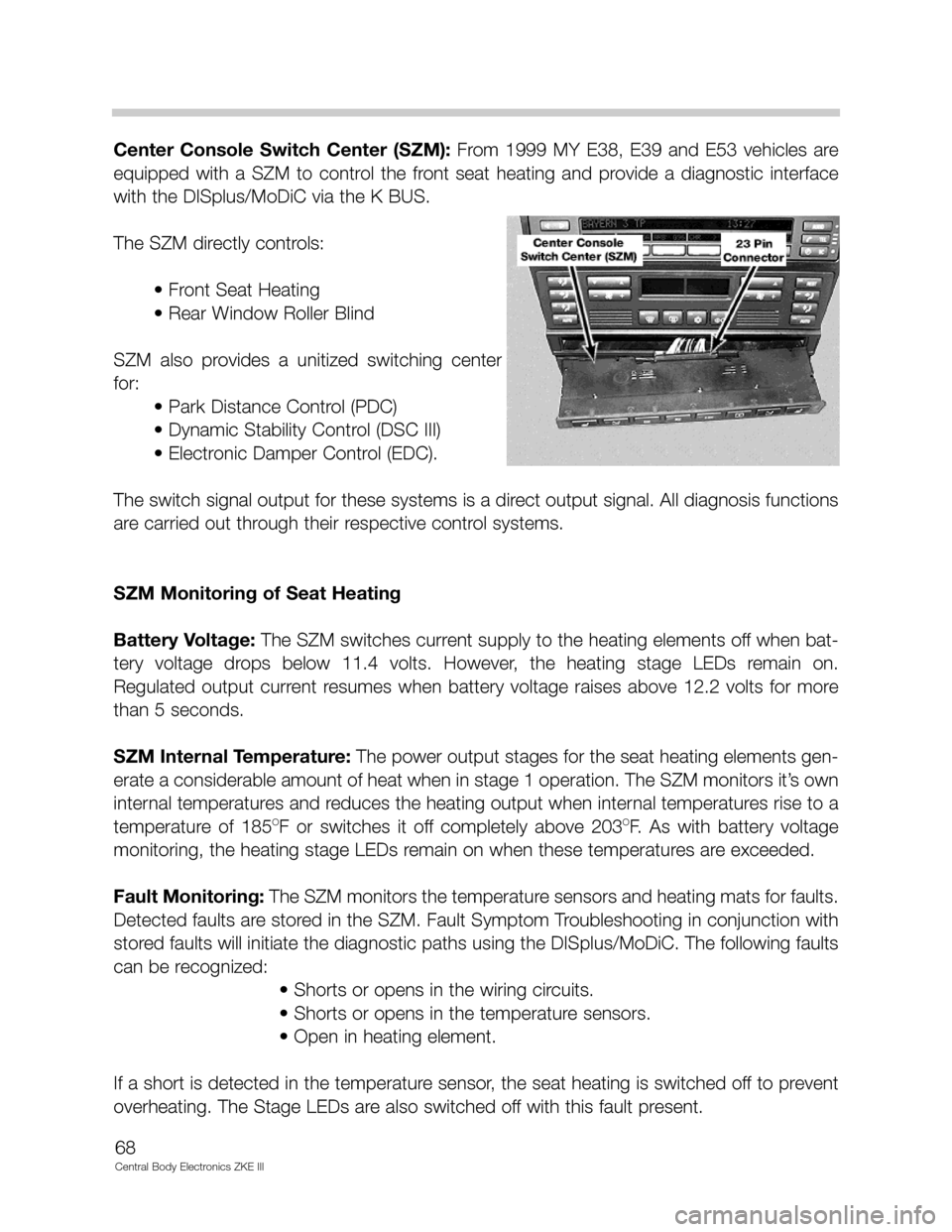
Center Console Switch Center (SZM): From 1999 MY E38, E39 and E53 vehicles are
equipped with a SZM to control the front seat heating and provide a diagnostic interface
with the DISplus/MoDiC via the K BUS.
The SZM directly controls:
• Front Seat Heating
• Rear Window Roller Blind
SZM also provides a unitized switching center
for:
• Park Distance Control (PDC)
• Dynamic Stability Control (DSC III)
• Electronic Damper Control (EDC).
The switch signal output for these systems is a direct output signal. All diagnosis functions
are carried out through their respective control systems.
SZM Monitoring of Seat Heating
Battery Voltage:The SZM switches current supply to the heating elements off when bat-
tery voltage drops below 11.4 volts. However, the heating stage LEDs remain on.
Regulated output current resumes when battery voltage raises above 12.2 volts for more
than 5 seconds.
SZM Internal Temperature: The power output stages for the seat heating elements gen-
erate a considerable amount of heat when in stage 1 operation. The SZM monitors it’s own
internal temperatures and reduces the heating output when internal temperatures rise to a
temperature of 185
OF or switches it off completely above 203OF. As with battery voltage
monitoring, the heating stage LEDs remain on when these temperatures are exceeded.
Fault Monitoring:The SZM monitors the temperature sensors and heating mats for faults.
Detected faults are stored in the SZM. Fault Symptom Troubleshooting in conjunction with
stored faults will initiate the diagnostic paths using the DISplus/MoDiC. The following faults
can be recognized:
• Shorts or opens in the wiring circuits.
• Shorts or opens in the temperature sensors.
• Open in heating element.
If a short is detected in the temperature sensor, the seat heating is switched off to prevent
overheating. The Stage LEDs are also switched off with this fault present.