GM III Low General Module BMW 525I 2002 E39 Central Body Electronics ZKE Manual
[x] Cancel search | Manufacturer: BMW, Model Year: 2002, Model line: 525I, Model: BMW 525I 2002 E39Pages: 80, PDF Size: 4.14 MB
Page 3 of 80
3
Central Body Electronics ZKE III
Central Body Electronics (ZKE III)
Purpose of the System
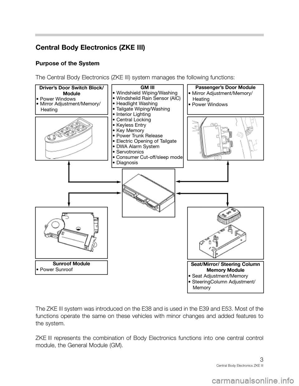
The Central Body Electronics (ZKE III) system manages the following functions:
GM III
• Windshield Wiping/Washing
• Windsheild Rain Sensor (AIC)
• Headlight Washing
• Tailgate Wiping/Washing
• Interior Lighting
• Central Locking
• Keyless Entry
• Key Memory
• Power Trunk Release
• Electric Opening of Tailgate
• DWA Alarm System
• Servotronics
• Consumer Cut-off/sleep mode
• DiagnosisDriver’s Door Switch Block/
Module
• Power Windows
• Mirror Adjustment/Memory/
HeatingPassenger’s Door Module
• Mirror Adjustment/Memory/
Heating
• Power Windows
Sunroof Module
• Power SunroofSeat/Mirror/ Steering Column
Memory Module
• Seat Adjustment/Memory
• SteeringColumn Adjustment/
Memory
The ZKE III system was introduced on the E38 and is used in the E39 and E53. Most of the
functions operate the same on these vehicles with minor changes and added features to
the system.
ZKE III represents the combination of Body Electronics functions into one central control
module, the General Module (GM).
Page 4 of 80
4
Central Body Electronics ZKE III
System Components
General Module (GM): The GM is reponsible
for the operation and central coordination of
body electronics. The GM is a micro-computer
that is the central component (heart) of the
Central Body Electronics. The GM is located be-
hind the glove box.
The main objectives for using the GM are:
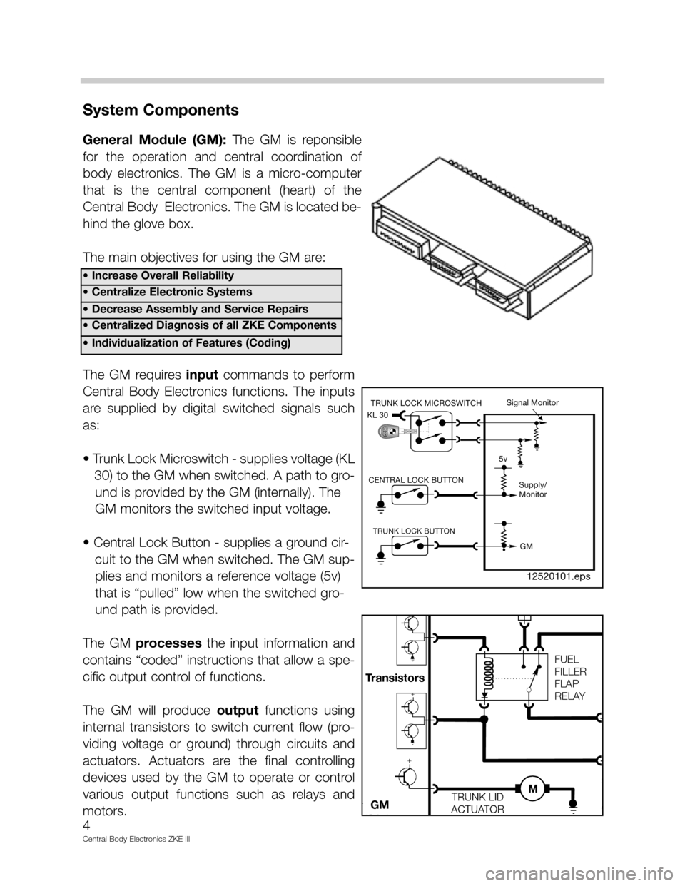
The GM requires inputcommands to perform
Central Body Electronics functions. The inputs
are supplied by digital switched signals such
as:
• Trunk Lock Microswitch - supplies voltage (KL
30) to the GM when switched. A path to gro-
und is provided by the GM (internally). The
GM monitors the switched input voltage.
• Central Lock Button - supplies a ground cir-
cuit to the GM when switched. The GM sup-
plies and monitors a reference voltage (5v)
that is “pulled” low when the switched gro-
und path is provided.
The GM processesthe input information and
contains “coded” instructions that allow a spe-
cific output control of functions.
The GM will produce outputfunctions using
internal transistors to switch current flow (pro-
viding voltage or ground) through circuits and
actuators. Actuators are the final controlling
devices used by the GM to operate or control
various output functions such as relays and
motors.
• Increase Overall Reliability
• Centralize Electronic Systems
• Decrease Assembly and Service Repairs
• Centralized Diagnosis of all ZKE Components
• Individualization of Features (Coding)
CENTRAL LOCK BUTTONCENTRAL LOCK BUTTON
TRUNK LOCK BUTTONTRUNK LOCK BUTTON
KL 30KL 30
TRUNK LOCK MICROSWITCHTRUNK LOCK MICROSWITCHSignal Monitor
5v
Supply/
Monitor
GM
FUEL
FILLER
FLAP
RELAY
Transistors
GM
12520101.eps
Page 5 of 80
5
Central Body Electronics ZKE III
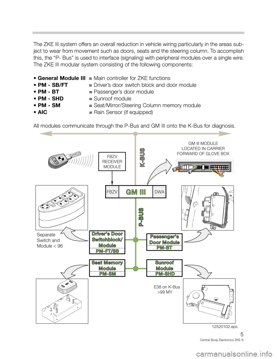
The ZKE III system offers an overall reduction in vehicle wiring particularly in the areas sub-
ject to wear from movement such as doors, seats and the steering column. To accomplish
this, the “P- Bus” is used to interface (signaling) with peripheral modules over a single wire.
The ZKE III modular system consisting of the following components:
• General Module III = Main controller for ZKE functions
• PM - SB/FT = Driver’s door switch block and door module
• PM - BT = Passenger’s door module
• PM - SHD =Sunroof module
•PM - SM =Seat/Mirror/Steering Column memory module
• AIC = Rain Sensor (if equipped)
All modules communicate through the P-Bus and GM III onto the K-Bus for diagnosis.
PM-FT/SB
PM-SMPM-BT
PM-SHD
P-BUS
K-BUS
Driver's Door
Switchblock/
ModuleDriver's Door
Switchblock/
Module
Seat Memory
ModuleSeat Memory
Module
Passenger's
Door ModulePassenger's
Door Module
Sunroof
ModuleSunroof
Module
GM IIIFBZVFBZVDWADWA
FBZV
RECEIVER
MODULE
GM III MODULE
LOCATED IN CARRIER
FORWARD OF GLOVE BOX
Separate
Switch and
Module < 96
E38 on K-Bus
>99 MY
12520102.eps
Page 6 of 80
6
Central Body Electronics ZKE III
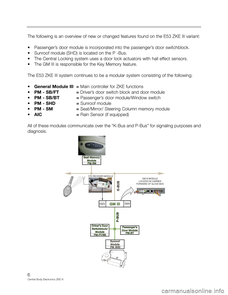
The following is an overview of new or changed features found on the E53 ZKE III variant:
• Passenger’s door module is incorporated into the passenger’s door switchblock.
• Sunroof module (SHD) is located on the P -Bus.
• The Central Locking system uses a door lock actuators with hall effect sensors.
• The GM III is responsible for the Key Memory feature.
The E53 ZKE III system continues to be a modular system consisting of the following:
•General Module III = Main controller for ZKE functions
•PM - SB/FT = Driver’s door switch block and door module
•PM - SB/BT =Passenger’s door module/Window switch
•PM - SHD =Sunroof module
•PM - SM =Seat/Mirror/ Steering Column memory module
•AIC = Rain Sensor (if equipped)
All of these modules communicate over the “K-Bus and P-Bus” for signaling purposes and
diagnosis.
Page 28 of 80

Vehicle Memory: The owner is provided with a list of available system functions that can
be customized to their liking. Prior to delivery, the DISplus or MoDiC is used to encode the
owner’s chosen selections into the appropriate control modules.
These choices become a permanent function of the control module and can only be
changed by re-encoding with the DISplus or MoDiC at a BMW Center.
This feature has been available for some time via the ZCS Conversion Feature but has
never been fully utilized or officially presented to the vehicle owner as a feature of their vehi-
cle.
Key Memory: This feature provides the added convenience of identifying users of the vehi-
cle whenever a lock or unlocked signal is generated via the individual FZV keys. A maxi-
mum of four FZV keys can be used with the Key Memory feature.
Each of the four keys generate a unique key identification signal (key number) that is trans-
mitted simultaneously with the lock/unlock signals to the General Module. Key Memory
does not respond to Lock/Unlock requests from the drivers door lock.
Mostof the key memory functions require the vehicle be configured using the “KEY MEM-
ORY” function of the DIS or MoDiC. However, there are a few features that store settings
automatically without configuration such as IHKA blower speed and temp setting. The key
ID signal alerts the GM to communicate with select control systems over the K Bus to store
(when locked) or reset (when unlocked) certain driver adjustable settings.
There are features that function as both a Car & Key Memory feature.
Example; the Automatic Seat Adjustment feature is encoded as a Car Memory Function
with the following possibilities:
• When unlocking,
• When opening a door after unlocking
• Or not active at all.
If active, the seat positions are stored and reactivated by the Key Memory function for indi-
vidual users of the car.
Notes: _______________________________________________________________________
_____________________________________________________________________________
_____________________________________________________________________________
_____________________________________________________________________________
_____________________________________________________________________________
28
Central Body Electronics ZKE III
Page 33 of 80
Anti-Theft (DWA) System
Purpose of the System
The DWA alarm system offers vehicle protection by monitoring the doors, hood, interior,
luggage compartment and vehicle tilting. When activated, DWA deters theft by sounding
an alarm siren for 30 seconds, flashing the low beam headlights (high beam on Xenon
equipped models) and four way flashers for 5 minutes.
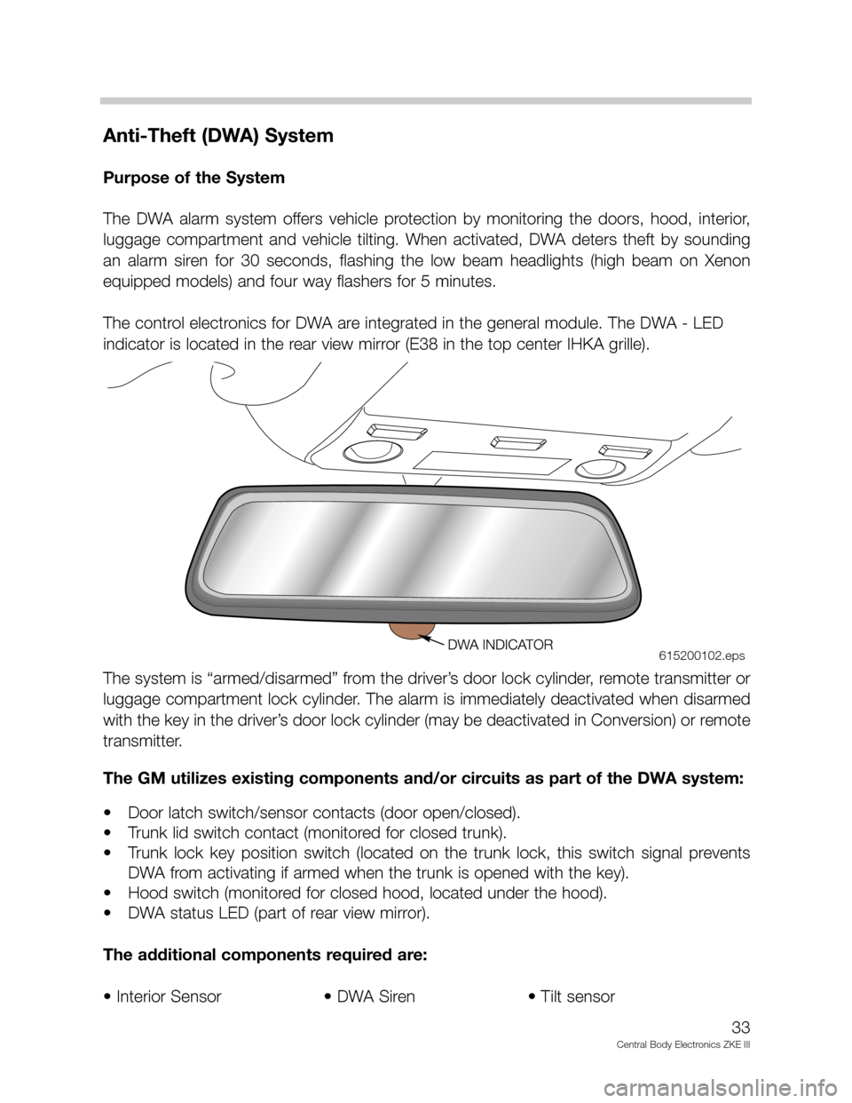
The control electronics for DWA are integrated in the general module. The DWA - LED
indicator is located in the rear view mirror (E38 in the top center IHKA grille).
The system is “armed/disarmed” from the driver’s door lock cylinder, remote transmitter or
luggage compartment lock cylinder. The alarm is immediately deactivated when disarmed
with the key in the driver’s door lock cylinder (may be deactivated in Conversion) or remote
transmitter.
The GM utilizes existing components and/or circuits as part of the DWA system:
• Door latch switch/sensor contacts (door open/closed).
• Trunk lid switch contact (monitored for closed trunk).
• Trunk lock key position switch (located on the trunk lock, this switch signal prevents
DWA from activating if armed when the trunk is opened with the key).
• Hood switch (monitored for closed hood, located under the hood).
• DWA status LED (part of rear view mirror).
The additional components required are:
• Interior Sensor • DWA Siren • Tilt sensor
33
Central Body Electronics ZKE III
615200102.eps
Page 53 of 80
System Components
Door Contacts: As mentioned in the Central Locking Section, the existing door contacts
opened/closed are also an input for the interior lighting function. The E53 uses the Hall
effect sensors for the purpose of monitoring door open/closed status (located directly
behind the rotary latch plate encased in the actuator). The sensor is activated by the rotary
latch plate's position.
• Door closed, the rotary latch plate is in the latched position. Current flow through the
hall sensor is < 5 mA.
• Door open, the rotary latch plate is in the open position. Current flow through the hall
sensor is > 12 mA.
A change in current flow informs the General module when a door is opened or closed.
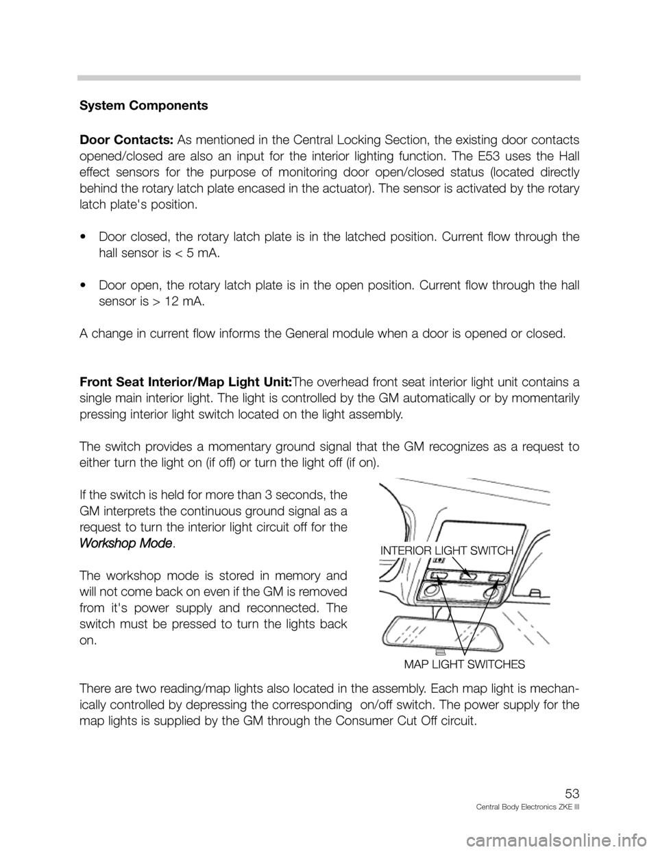
Front Seat Interior/Map Light Unit:The overhead front seat interior light unit contains a
single main interior light. The light is controlled by the GM automatically or by momentarily
pressing interior light switch located on the light assembly.
The switch provides a momentary ground signal that the GM recognizes as a request to
either turn the light on (if off) or turn the light off (if on).
If the switch is held for more than 3 seconds, the
GM interprets the continuous ground signal as a
request to turn the interior light circuit off for the
Workshop Mode
.
The workshop mode is stored in memory and
will not come back on even if the GM is removed
from it's power supply and reconnected. The
switch must be pressed to turn the lights back
on.
There are two reading/map lights also located in the assembly. Each map light is mechan-
ically controlled by depressing the corresponding on/off switch. The power supply for the
map lights is supplied by the GM through the Consumer Cut Off circuit.
53
Central Body Electronics ZKE III
Page 75 of 80
General Functions of ZKE III
Consumer Cut Off
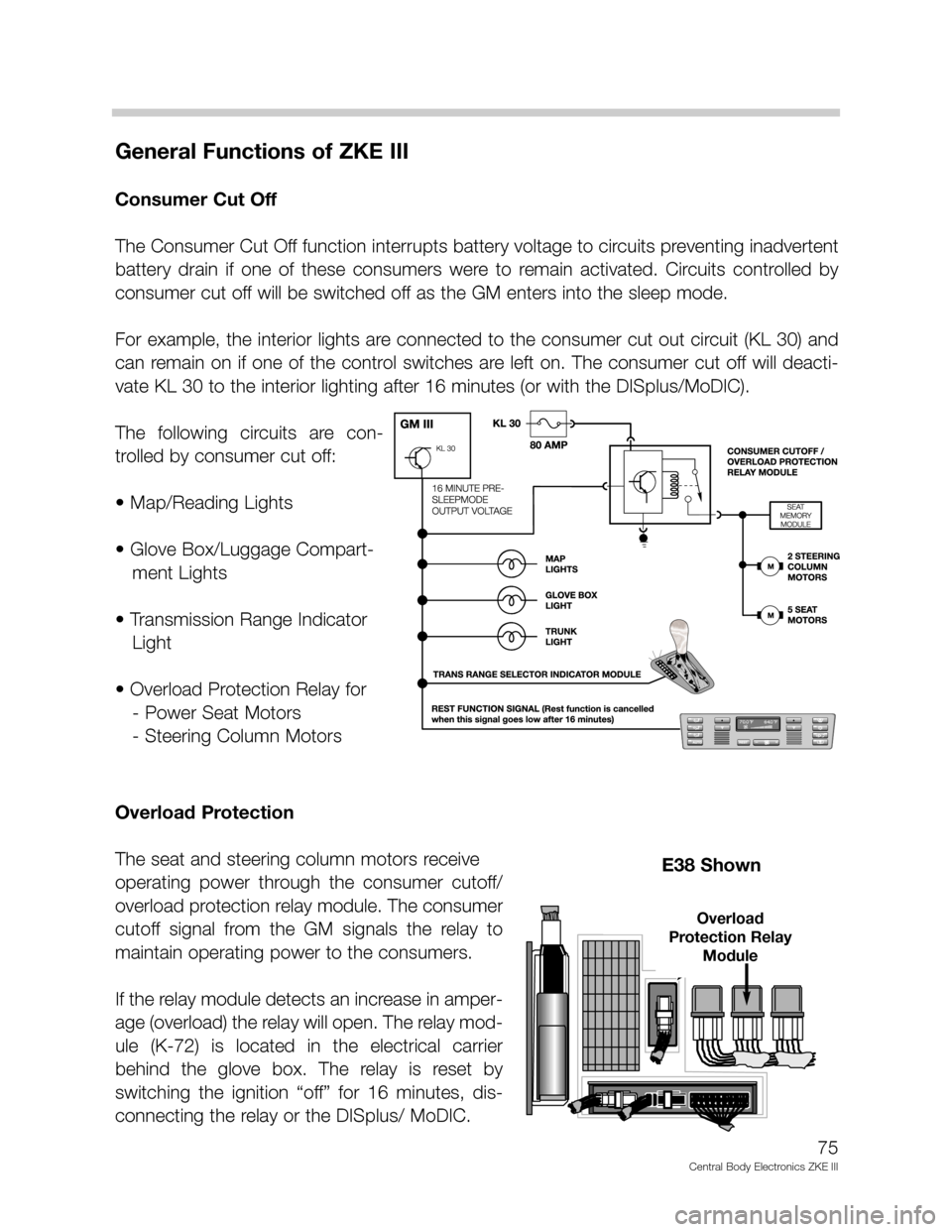
The Consumer Cut Off function interrupts battery voltage to circuits preventing inadvertent
battery drain if one of these consumers were to remain activated. Circuits controlled by
consumer cut off will be switched off as the GM enters into the sleep mode.
For example, the interior lights are connected to the consumer cut out circuit (KL 30) and
can remain on if one of the control switches are left on. The consumer cut off will deacti-
vate KL 30 to the interior lighting after 16 minutes (or with the DISplus/MoDIC).
The following circuits are con-
trolled by consumer cut off:
• Map/Reading Lights
• Glove Box/Luggage Compart-
ment Lights
• Transmission Range Indicator
Light
• Overload Protection Relay for
- Power Seat Motors
- Steering Column Motors
Overload Protection
The seat and steering column motors receive
operating power through the consumer cutoff/
overload protection relay module. The consumer
cutoff signal from the GM signals the relay to
maintain operating power to the consumers.
If the relay module detects an increase in amper-
age (overload) the relay will open. The relay mod-
ule (K-72) is located in the electrical carrier
behind the glove box. The relay is reset by
switching the ignition “off” for 16 minutes, dis-
connecting the relay or the DISplus/ MoDIC.
75
Central Body Electronics ZKE III
E38 Shown
Overload
Protection Relay
Module
Page 76 of 80
Sleep Mode
To lower the constant battery draw when the vehicle is parked, the complete ZKE system
will go into the “Sleep Mode” 16 minutes after the ignition has been switched off and no
further ZKE function is active.
For example, the approximate E39 (528i) Battery draw is:
• Ignition switch off = approx 750 mA.
• One minute after = approx. 560 mA.
• After 16 minutes (sleep mode) = approx. 18 mA.
All modules in the ZKE system will go into the sleep mode. The P-Bus remains active, how-
ever no data transfer takes place until a wake-up request is received. The general module,
door modules or keyless remote module can wake the system up and put the ZKE back
on line. The K-Bus is active (high) in the sleep mode.
Sleep Mode Criteria:
KL R, KL 15 OFF and no further function activated for 16 minutes.
Wake Up Criteria:
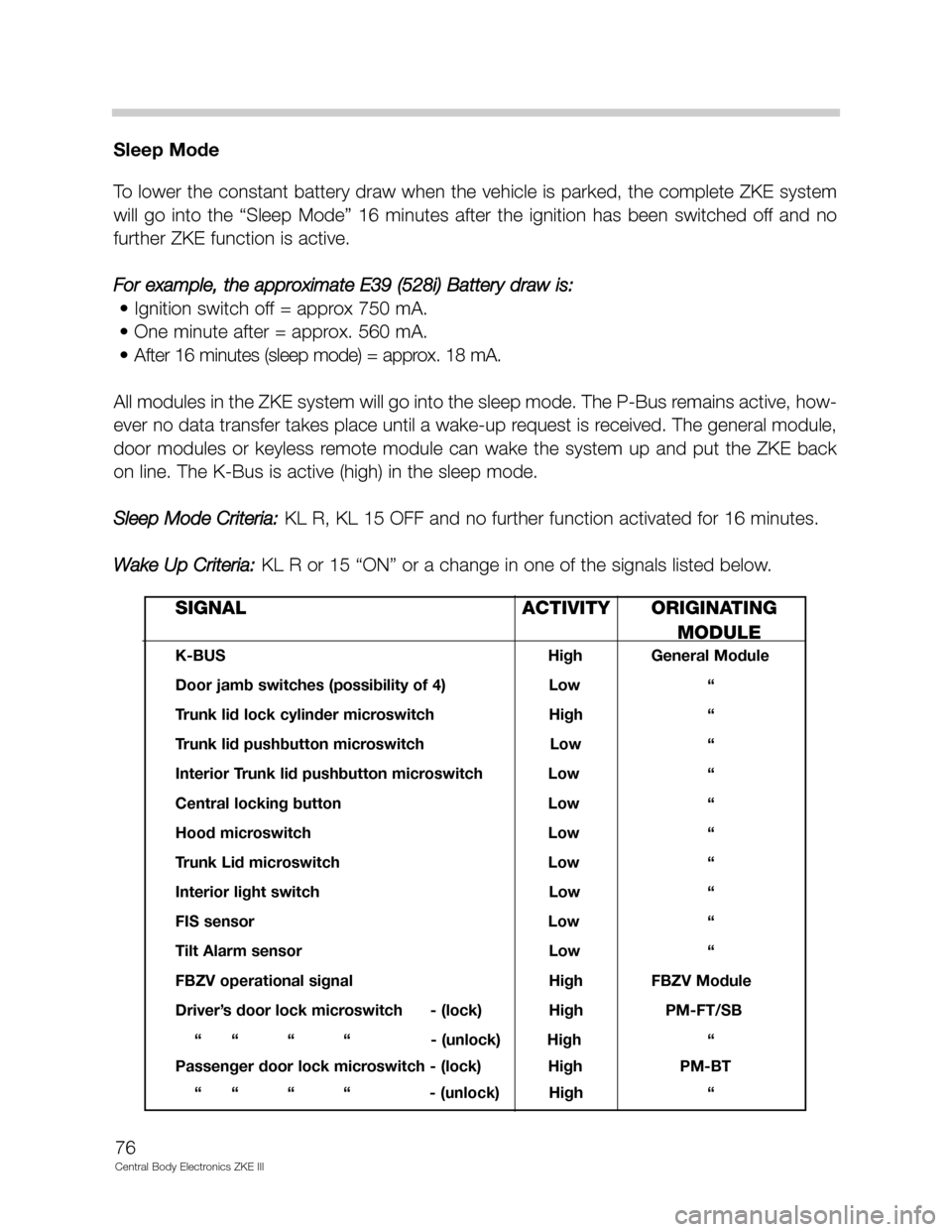
KL R or 15 “ON” or a change in one of the signals listed below.
76
Central Body Electronics ZKE III
SIGNAL ACTIVITY ORIGINATING
MODULE
K-BUS High General Module
Door jamb switches (possibility of 4) Low “
Trunk lid lock cylinder microswitch High “
Trunk lid pushbutton microswitch Low “
Interior Trunk lid pushbutton microswitch Low “
Central locking button Low “
Hood microswitch Low “
Trunk Lid microswitch Low “
Interior light switch Low “
FIS sensor Low “
Tilt Alarm sensor Low “
FBZV operational signal High FBZV Module
Driver’s door lock microswitch - (lock) High PM-FT/SB
“ “ “ “ - (unlock) High “
Passenger door lock microswitch - (lock) High PM-BT
“ “ “ “ - (unlock) High “