spark plugs BMW 528i 1997 E39 Workshop Manual
[x] Cancel search | Manufacturer: BMW, Model Year: 1997, Model line: 528i, Model: BMW 528i 1997 E39Pages: 1002
Page 25 of 1002
Downloaded from www.Manualslib.com manuals search engine
Sockets Socltets are used with a ratchet handle for speed and conve-
nience and can be combined with extensions and universal
joints (swivels) to reach fasteners more easily. The most
common socket drive sizes are
114 inch, 318 inch and 112 inch.
Sockets come in
6 point and 12 point styles. The 6 point offers
a better grip on tight nuts and bolts.
6 mm to 19 mm socltets
are the most needed sizes. Below is a list of typical bolt
diarn-
eters and the corresponding wrench sizes.
Common bolt diameters and wrench sizes
M5 8 rnrn
M6
10 rnm
M8 12rnrnor13rnrn
MI 0 17 rnrn
MI2 19 rnrn
M14 22 mm
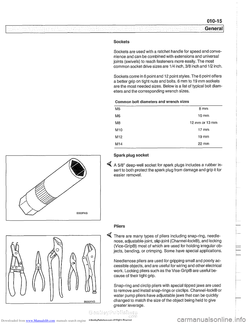
Spark plug socket
4 A 518" deep-well socket for sparlt plugs includes a rubber in-
sert to both protect the spark plug from damage and grip it for
easier removal.
Pliers
There are many types of pliers including snap-ring,
needle-
nose, adjustable-joint, slip-joint (Channel-lock@), and locking
(Vice-Grip@) most of which are used for holding irregular ob-
jects, bending, or crimping. Some have special applications.
Needlenose pliers are used for gripping small and poorly ac-
cessible objects, and are useful forwiring and other electrical
work. Locking pliers such as the Vise-Grip@ are useful be-
cause of their tight grip.
Snap-ring and circlip pliers with special tipped jaws are used
to remove and install snap-rings or circlips. Channel-lock@ or
water pump pliers have adjustable jaws that can be quicltly
changed to match the size of the object being held to give
greater leverage,
Page 33 of 1002
Downloaded from www.Manualslib.com manuals search engine
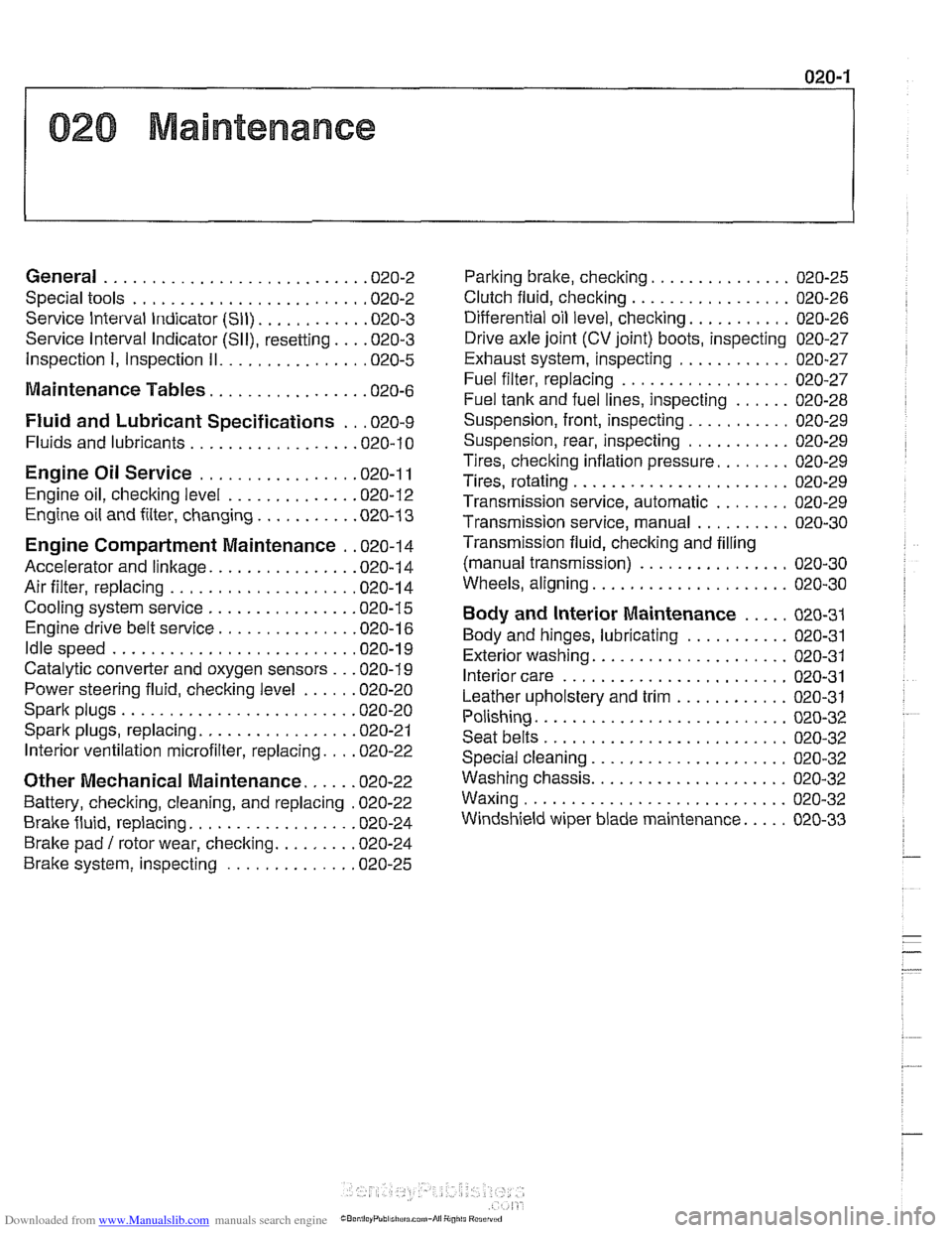
020 Maintenance
General ........................... .02 0.2
Special tools ........................ .02 0.2
Service Interval Indicator (Sll) ........... .02 0.3
Service Interval Indicator (Sll), resetting ... .02 0.3
Inspection I, Inspection 11 ............... .02 0.5
Maintenance Tables ................ .02 0.6
Fluid and Lubricant Specifications .. .02 0.9
Fluids and lubricants ................. .02 0.10
Engine Oil Service ................ .02 0.1 I
Engine oil. checking level ............. .02 0.12
Engine oil and filter. changing .......... .02 0-13
Engine Compartment Maintenance . .02 0.14
Accelerator and linkage ............... .02 0.14
Air filter. replacing ................... .02 0.1 4
Cooling system service ............... .02 0.15
Engine drive belt service .............. .02 0.16
Idlespeed .......................... 020-19
Catalytic converter and oxygen sensors .. .02 0.19
Power steering fluid, checking level ..... .02 0.20
Spark plugs ........................ .02 0.20
Spark plugs, replacing ................ .02 0.21
Interior ventilation microfilter, replacing ... .02 0.22
Other Mechanical Maintenance ..... .02 0.22
Battery, checking. cleaning. and replacing .02 0-22
Brake fluid. replacing ................. .02 0-24
Brake pad 1 rotor wear. checking ........ .02 0.24
Brake system, inspecting ............. .02 0.25
Parking brake. checking ............... 020-25
Clutch fluid. checking ................. 020-26
Differential oil level. checking ........... 020-26
Drive axle joint (CV joint) boots. inspecting 020-27
Exhaust system. inspecting ............ 020-27
Fuel filter. replacing .................. 020-27
Fuel tank and fuel lines. inspecting ...... 020-28
Suspension. front. inspecting ........... 020-29
Suspension. rear. inspecting ........... 020-29
Tires. checking inflation pressure ........ 020-29
Tires. rotating ....................... 020-29
Transmission service. automatic ........ 020-29
Transmission service. manual .......... 020-30
Transmission fluid. checking and filling
(manual transmission)
................ 020-30
Wheels. aligning ..................... 020-30
Body and Interior Maintenance ..... 020-31
Body and hinges. lubricating ........... 020-31
Exterior washing ..................... 020-31
Interior care ........................ 020-31
Leather upholstery and trim ............ 020-31
Polishing ........................... 020-32
Seat belts .......................... 020-32
Special cleaning ..................... 020-32
Washing chassis ..................... 020-32
Waxing ............................ 020-32
Windshield wiper blade maintenance ..... 020-33
Page 41 of 1002
Downloaded from www.Manualslib.com manuals search engine
--- -
Maintenance
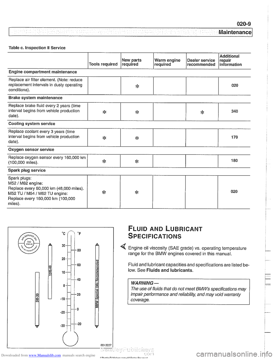
Table c. Inspection II Service
Additional
New parts Warm engine Dealer service repair
Tools required required required recommended information
Engine compartment maintenance
Replace air filter element. (Note: reduce
replacement intervals in dusty operating
conditions).
Replace brake
fluid every 2 years (time
interval begins from vehicle production
date).
Cooling system service
Spark plug service
Brake
system maintenance
:j:
*
Replace coolant every 3 years (time
interval begins from vehicle production
date).
Replace oxygen sensor every 160,000
itm
(1 00,000 miles).
020
FLUID AND LUBRICANT
SPECIFICATIONS
:I:
Oxygen sensor service
*
x:
Spark plugs:
M52
1 M62 engine:
Replace every 60,000 itm (48.000 miles).
M52
TU I M54 1 M62 TU engine:
Replace every 160,000
ltm (100.000
miles).
< Engine oil viscosity (SAE grade) vs. operating temperature
range for the BMW engines covered in this manual.
Fluid and lubricant capacities and specifications are listed be-
low. See
Fluids and lubricants.
:I:
*
*
*
WARNING -
The use of fluids that do not meet BMW" specifications may
impair performance and
reliabilitl: and may void warranty
coverage.
340
170
180
* 020
Page 52 of 1002
Downloaded from www.Manualslib.com manuals search engine
Maintenance
continue to operate as designed. Extending the replacement
interval may void the emission control warranty coverage.
See
180 Exhaust System for information on replacing the
oxygen sensors.
Tightening torque
Oxvoen sensor to exhaust
manifold 50 Nrn (37 ft-lb)
NOTE-
A special soclet for replacing the oxygen sensor is available
from most automotive parts stores. The soclet has
a groove
cut down one side to allow the sensor to be installed without
damaging the wire harness.
Power steering fluid, checking level
The power steering system is permanently filled and does not
have a drain. Routinely adding ATF is not required unless the
system is leaking.
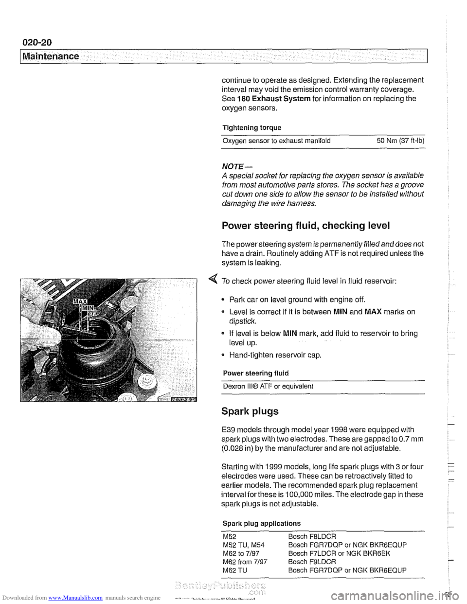
4 To check power steering fluid level in fluid reservoir:
Park car on level ground with engine off.
Level is correct
if it is between MlN and MAX marks on
dipstick.
If level is below
MlN mark, add fluid to reservoir to bring
level up.
* Hand-tighten reservoir cap.
Power steering fluid
Dexron
1iiO ATF or equivalent
Spark plugs
E39 models through model year 1998 were equipped with
spark plugs with two electrodes. These are gapped to
0.7 mm
(0.028 in) by the manufacturer and are not adjustable.
Starting with 1999 models, long life spark plugs with
3 or four
electrodes were used. These can be retroactively fitted to
earlier
models. The recommended spark plug replacement
interval
forthese is 100,000 miles.The electrode gap in these
spark plugs is not adjustable.
Spark plug applications
M52 Bosch FBLDCR
M52 TU, M54 Bosch FGR7DQP or NGK BKRBEQUP
M62 to 7/97 Bosch F7LDCR or NGK BKR6EK
M62 from 7/97 Bosch F9LDCR
M62 TU Bosch FGR7DQP or NGK BKRGEQUP
Page 53 of 1002
Downloaded from www.Manualslib.com manuals search engine
020-21
Maintenance
Spark plugs, replacing
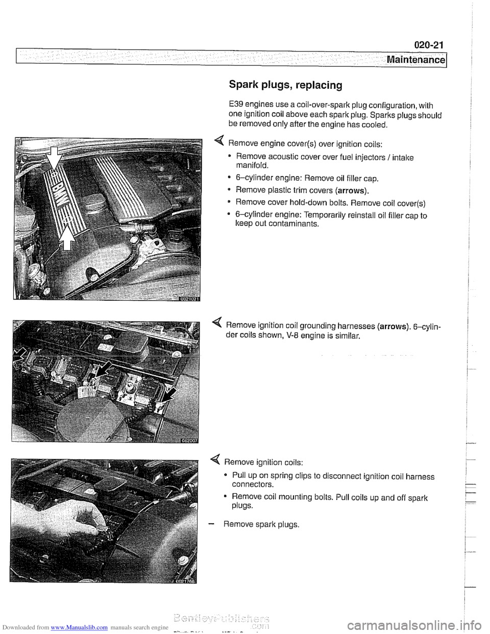
E39 engines use a coil-over-spark plug configuration, with
one ignition coil above each spark plug. Sparks plugs should
be removed only after the engine has cooled.
Remove engine
cover(s) over ignition coils:
Remove acoustic cover over fuel injectors
I intake
manifold.
6-cylinder engine: Remove oil filler cap.
Remove plastic trim covers (arrows).
Remove cover hold-down bolts. Remove coil
cover(s)
6-cylinder engine: Temporarily reinstall oil filler cap to
keep out contaminants.
Remove ignition coil grounding harnesses (arrows). 6-cylin-
der coils shown,
V-8 engine is similar.
< Remove ignition coils:
Pull up on spring clips to disconnect ignition coil harness
connectors.
Remove coil mounting bolts. Pull coils up and off spark
plugs.
- Remove spark plugs.
Page 54 of 1002
Downloaded from www.Manualslib.com manuals search engine
020-22 Maintenance
1
- Installation is reverse of removal, bearing in mind the
following:
Lightly lubricate new
spark plug threads with
copper-based anti-seize compound.
Thread plugs into cylinder head by hand to prevent
cross-threading.
. Be sure to reinstall and tighten coil grounds.
Tightening torque Spark plug
to cylinder head 25 Nm (18 It-lb)
Interior ventilation microfilter, replacing
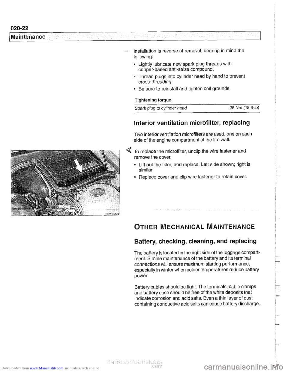
Two interior ventilation microfilters are used, one on each
side of the engine compartment at the fire wall.
< To replace the microfilter, unclip the wire fastener and
remove the cover.
Lift out the filter, and replace. Left side shown; right is
similar.
Replace cover and clip wire fastener to retain cover.
Battery, checking, cleaning, and replacing
The battery Is located in the right side of the luggage compart-
ment. Simple maintenance of the battery and its terminal
connections will ensure maximum starting periormance,
especially in winter when colder temperatures reduce battery
power.
Battery cables should be tight. The terminals, cable clamps
and battery case should be free of the white deposits that
indicate corrosion and acid salts. Even a thin layer of dust
containing conductive acid salts can cause battery discharge.
Page 100 of 1002
Downloaded from www.Manualslib.com manuals search engine
11 3-6
Cylinder Head Removal and Installation
- Disable ignition system by removing DME main relay. See
610 Component Locations for relay location.
WARNING-
. The ignition system produces high voltages that can be fa-
tal. Avoid contact with exposed terminals and use
exfreme
caution when working on a car with the ignition switched on
or the engine running.
Do not touch or disconnect ignition
components while
the engine is running or being cranked by the starter.
Failure to remove the DME main relay or attempting to
disa-
bie the fuel andignition systems by other methods may result
in damaoe to the enoine control module
(ECM).
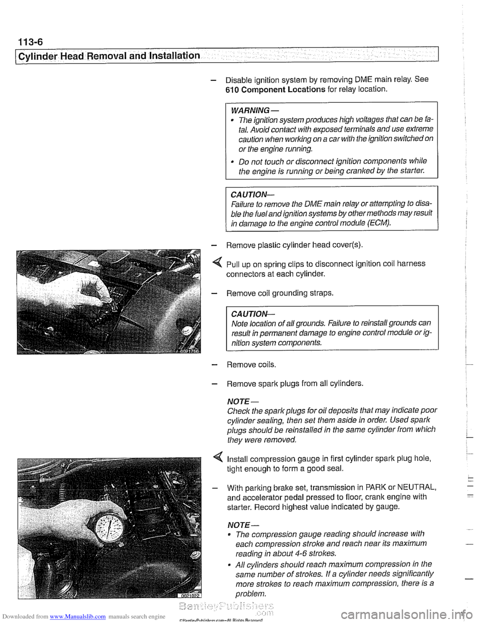
- - Remove plastic cylinder head cover(s)
,,I . ,. .*,.,,&- - Remove coil grounding straps.
I CAUTION-
I nition system components. I
- Remove coils.
- Remove spark plugs from all cylinders.
NOTE-
Check the spark plugs for oil deposits that may indicate poor
cylinder sealing, then set them aside in order. Used spark
plugs should be reinstalled in the same cylinder from which
they were removed.
4 Install compression gauge in first cylinder spark plug hole,
tight enough to form a good seal.
- With parking brake set, transmission in PARK or NEUTRAL,
and accelerator pedal pressed to floor, crank engine with
starter. Record highest value indicated by gauge.
NOTE-
* The compression gauge reading should increase with
each compression stroke and reach near its maximum
reading in about
4-6 strokes.
All cylinders should reach maximum compression in the
same number of
strolces. If a cylinder needs significantly
more strokes to reach
maximum compression, there is a
problem.
Page 101 of 1002
Downloaded from www.Manualslib.com manuals search engine
. .- . --
Lr -- - - - -- Cylinder Head Removal and Installation I -
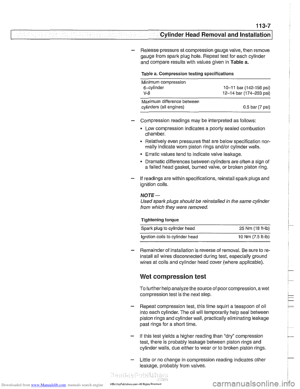
- Release pressure at compression gauge valve, then remove
gauge from spark plug hole. Repeat test for each cylinder
and compare results with values given in Table a.
Table a. Compression testing specifications
Minimum compression
6-cylinder
10-1 1 bar (142-156 psi)
V-8 12-14 bar (174-203 psi)
Maximum difference between
cylinders (all engines)
0.5 bar (7 psi)
- Compression readings may be interpreted as follows:
Low compression indicates a poorly sealed combustion
chamber.
0 Relatively even pressures that are below specification nor-
mally indicate worn piston rings
andlor cylinder walls.
Erratic values tend to indicate valve leakage.
Dramatic differences between cylinders are often a sign of
a failed head
gasket, burned valve, or broken piston ring.
- If readings are within specifications, reinstall spark plugs and
ignition coils.
NOTE-
Used spark plugs should be reinstalled in the same cylinder
from which they were removed.
Tightening torque Spark plug to cylinder head 25 Nm
(18 ft-lb)
lanition coils to cylinder head 10 Nm (7.5 ft-lb)
- Remainder of installation is reverse of removal. Be sure to re-
install all wires disconnected during test, especially ground
wires at coils and cylinder head cover (where applicable).
Wet compression test
To further help analyze the source of poorcompression,awet
compression test is the next step.
- Repeat compression test, this time squirt a teaspoon of oil
into each cylinder. The oil will temporarily help seal between
piston rings and cylinder wall, practically eliminating leakage
past rings for a short time.
- If this test yields a higher reading than "dry" compression
test, there is probably leakage between piston rings and
cylinder walls, due either to wear or to broken piston rings.
- Little or no change in compression reading indicates other
leakage, probably from valves.
Page 123 of 1002
Downloaded from www.Manualslib.com manuals search engine
Cylinder Head Removal and Installation
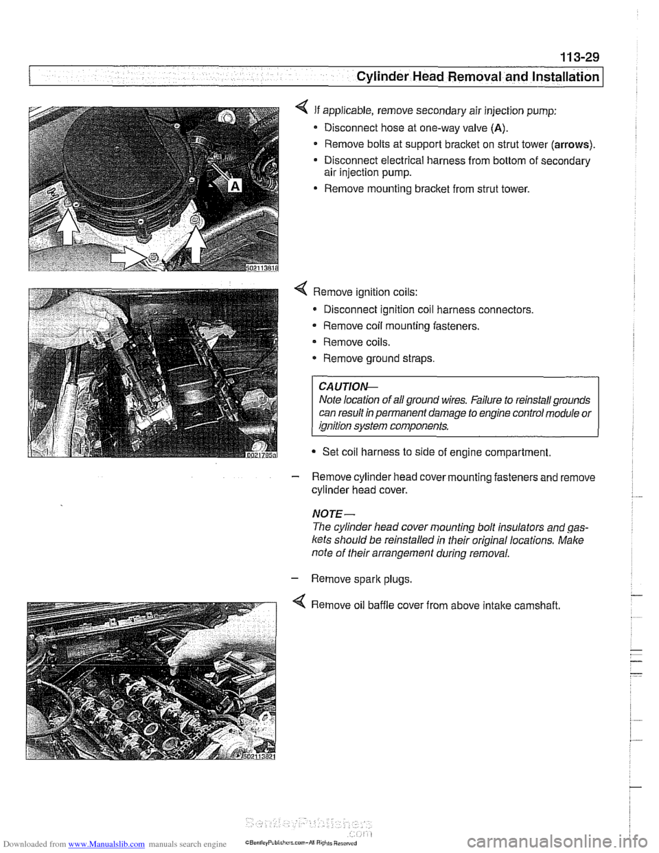
4 If applicable, remove secondary air injection pump:
Disconnect hose at one-way valve
(A).
Remove bolts at support bracket on strut tower (arrows).
Disconnect electrical harness from bottom of secondary
air injection pump.
Remove mounting bracket from strut tower.
4 Remove ignition coils:
* Disconnect ignition coil harness connectors.
Remove coil mounting fasteners.
Remove coils.
* Remove ground straps.
CA UTIOI\C
Note location of all ground wires. Failure to reinstall grounds
can result in permanent damage to engine control module or
ignition system components.
Set coil harness to side of engine compartment
- Remove cylinder head cover mounting fasteners and remove
cylinder head cover.
NOTE-
The cylinder head cover mounting bolt insulators and gas-
ltets should be reinstalled in their original locations. Male
note of their arrangement during removal.
- Remove spark plugs
4 Remove oil baffle cover from above intake camshaft.
Page 155 of 1002
Downloaded from www.Manualslib.com manuals search engine
11 3-61
Cylinder Head Removal and installation I
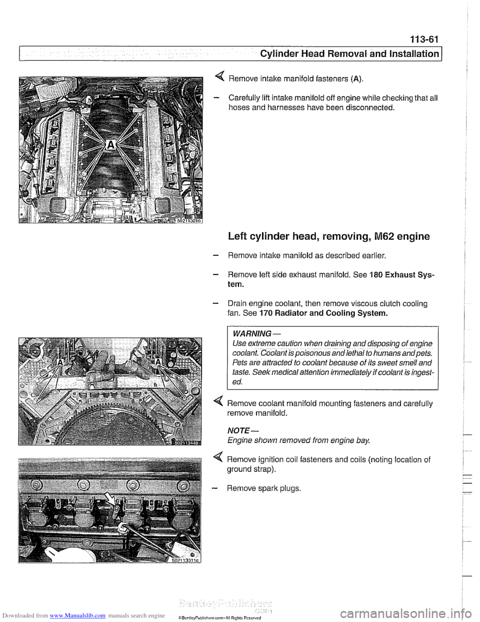
Remove intake manifold fasteners (A).
Carefully lift intake manifold off engine while checking that all
hoses and harnesses have been disconnected.
Left cylinder head, removing, M62 engine
- Remove intake manifold as described earlier
- Remove left side exhaust manifold. See 180 Exhaust Sys-
tem.
- Drain engine coolant, then remove viscous clutch cooling
fan. See
170 Radiator and Cooling System.
WARNING -
Use extreme caution when draining and disposfng of eng~ne
coolant. Coolant is poisonous and lethal to humans andpets.
Pets are attracted to coolant because of its sweet smell and
taste.
Seek med~cal attention immediately if coolant is ingest-
ed.
4 Remove coolant manifold mounting fasteners and carefully
remove manifold.
NOTE-
Engine shown removed from engine bay
4 Remove ignition coil fasteners and coils (noting location of
ground strap).
- Remove spark plugs.