electrical system BMW 528i 1997 E39 Workshop Manual
[x] Cancel search | Manufacturer: BMW, Model Year: 1997, Model line: 528i, Model: BMW 528i 1997 E39Pages: 1002
Page 783 of 1002
Downloaded from www.Manualslib.com manuals search engine
1 Brakes
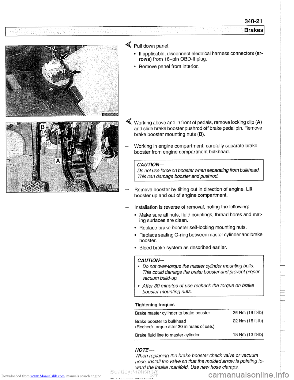
Pull down panel
If applicable, disconnect electrical harness
rows) from 16-pin OBD-ll plug.
Remove panel from interior. connectors
(ar-
Working
above and in front of pedals, remove locking clip (A)
and slide brake booster pushrod off bralte pedal pin. Remove
brake booster mounting nuts
(6).
Working in engine compartment, carefully separate bralte
booster from engine compartment bulkhead.
CAUTION-
Do not use force on booster when separating from bulkhead.
This can damage booster and pushrod.
Remove booster by tilting out in direction of engine. Lift
booster up and out of engine compartment.
- Installation is reverse of removal, noting the following:
Make sure all nuts, fluid couplings, thread bores and mat-
ing surfaces are clean.
Replace bralte booster self-locking mounting nuts.
Replace sealing O-ring between master cylinder and bralte
booster.
Bleed bralte system as described earlier.
CAUTION--
Do not over-torque tlie master cylinder mounting bolts.
This could damage the
bralce booster and prevent proper
vacuum build-up.
After
30 minutes of use recheclc the torque on bralce
booster mounting nuts.
Tightening torques
Brake master cylinder to brake booster
26 Nm (19 it-lb)
Brake booster to bulkhead 22 Nm (16 it-lb)
(Recheck torque after
30 minutes of use.)
Brake fluid line to master cylinder 18 Nm (13 it-lb)
NOTE-
When replacing the brake booster check valve or vacuum
hose, install the valve so that the molded arrow is pointing to-
ward the
fntalce manifold. Use new hose clamps
Page 789 of 1002
Downloaded from www.Manualslib.com manuals search engine
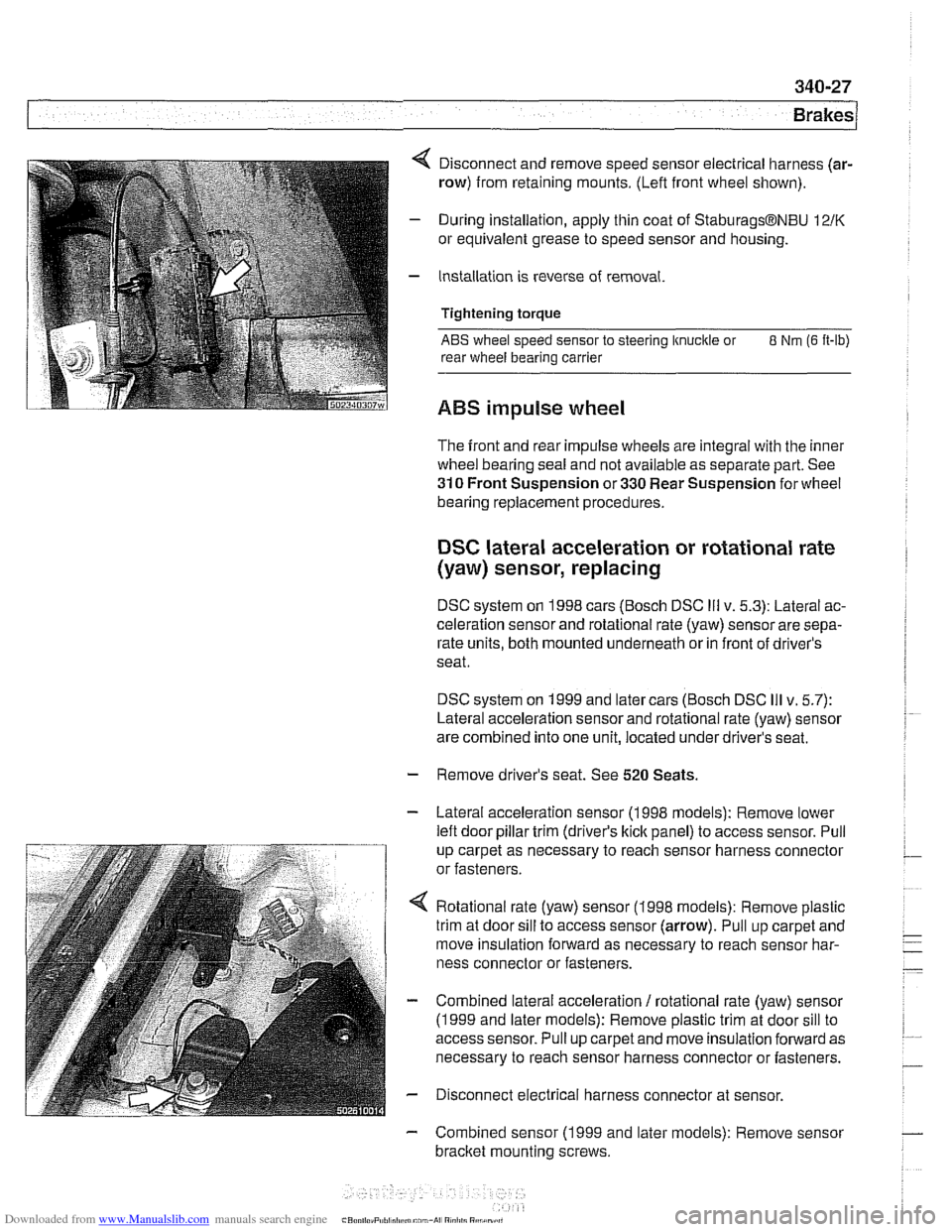
4 Disconnect and remove speed sensor electrical harness (ar-
row) from retaining mounts. (Lefl front wheel shown).
- During installation, apply thin coat of StaburagsBNBU 12/K
or equivalent grease to speed sensor and housing.
- Installation is reverse of removal.
Tightening torque
ABS wheel speed sensor to steering knuckle or 8 Nm (6 It-lb)
rear wheel bearing carrier
ABS impulse wheel
The front and rear impulse wheels are integral with the inner
wheel bearing seal and not available as separate part. See
310 Front Suspension or 330 Rear Suspension for wheel
bearing replacement procedures.
DSC lateral acceleration or rotational rate
(yaw) sensor, replacing
DSC system on 1998 cars (Bosch DSC Ill v. 5.3): Lateral ac-
celeration sensor and rotational rate (yaw) sensor are sepa-
rate units, both mounted underneath or in front of driver's
seat.
DSC system on 1999 and later cars (Bosch DSC
Ill v. 5.7):
Lateral acceleration sensor and rotational rate (yaw) sensor
are combined into one unit, located under driver's seat.
- Remove driver's seat. See 520 Seats.
- Lateral acceleration sensor (1 998 models): Remove lower
lefl door pillar trim (driver's
kick panel) to access sensor. Pull
up carpet as necessary to reach sensor harness connector
or fasteners.
4 Rotational rate (yaw) sensor (1998 models): Remove plastic
trim at door sill to access sensor (arrow). Pull up carpet and
move insulation forward as necessary to reach sensor har-
ness connector or fasteners.
- Combined lateral acceleration / rotational rate (yaw) sensor
(1 999 and later models): Remove plastic trim at door sill to
access sensor. Pull up carpet and move insulation forward as
necessary to reach sensor harness connector or fasteners.
- Disconnect electrical harness connector at sensor.
- Combined sensor (1 999 and later models): Remove sensor
bracket mounting screws.
Page 791 of 1002
Downloaded from www.Manualslib.com manuals search engine
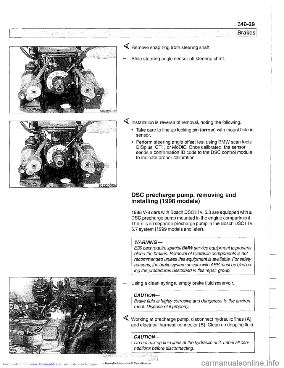
Remove snap ring from steering shaft.
- Slide steering angle sensor off steering shaft
< Installation is reverse of removal, noting the following.
Take care to line up loclting pin
(arrow) with mount hole in
sensor.
Perform steering angle offset test using BMW scan tools
DISplus, GT1, or MoDiC. Once calibrated, the sensor
sends a confirmation ID code to the DSC control module
to indicate proper calibration.
DSC precharge pump, removing and
installing
(1 998 models)
1998 V-8 cars with Bosch DSC Ill v. 5.3 are equipped with a
DSC precharge pump mounted in the engine compartment.
There is no separate precharge pump in the Bosch DSC
Ill v.
5.7 system (1999 models and later).
WARNING-
E39 cars require special BMWservice equipment to properly
bleed the brakes. Removal of hydraulic components is not
recommended unless this equipment is available. For safety
reasons, the
brake system on cars with ABS must be bled us-
ing the procedures described in this repair group.
- Using a clean syringe, empty brake fluid reservoir.
CAUTIOI\C
Brake fluid is highly corrosive and dangerous to the environ-
ment. Disoose of it
orooerlv.
Working at precharge pump, disconnect hydraulic lines (A)
and electrical harness connector (6). Clean up dripping fluid.
hydraulic unit. Label all
con-
Page 792 of 1002
Downloaded from www.Manualslib.com manuals search engine
1 Brakes
- Remove precharge pump mounting bracket fasteners and re-
move pump.
- Installation is reverse of removal, noting the following:
Be sure to replace rubber pump mounts if damaged
01
worn.
Bleed brakes as described earlier.
Tightening torque Brake line
to precharge pump 18 Nrn (13 ft-lb)
DSC pressure sensor (1 999 - 2002 models)
On 1999 and later DSC systems, the DSC pressure sensor is
screwed into the DSC hydraulic unit (right rear of engine com-
partment).
WARNING-
* €39 cars require special BMW service equipment to prop-
erly bleed the brakes. Removal of the
DSCpressure sensor
is not recommended unless this equipment is available. For
safety reasons, the brake system on cars with ABS must be
bled using the procedures described in this repair group.
Switch off ignition and remove
key to male sure brake
system cannot be activated.
- Disconnect electrical harness connector at switch.
- Use BMW special tool 34 5 160 to remove and install sensor.
Inspect threads and sealing surfaces for damage.
* Work quicltly to avoid excessive brake fluid leakage.
Tightening torque
Pressure sensor
to hydraulic 19 Nrn (14ft-lb)
unit
- Reconnect harness connector
- Bleed front brakes as described earlier.
- Press on brakes and check for leaks at sensor.
- Turn on ignition and firmly depress brake pedal. Check that
DSC warning light does not come on.
Page 799 of 1002
Downloaded from www.Manualslib.com manuals search engine
400-5
Body-General
Tailgate
The E39 Sporl Wagon tailgate is large with a low sill for easy
cargo loading. The tailgate opens to an angle of
88" mea-
sured from the rear roof pillar (D-pillar) and to a height of
2029
mm (79.8 in) measured from the ground to the upper edge of
the raised tailgate.
The rear window is bonded to a load bearing frame and can
be opened separately from the main tailgate. Tailgatesupport
gas springs are recessed into cavities in the roof.
Tailgate lock system
A mechanical tailgate lock cylinder is not used; the tailgate is
opened by the unlock pad above the license plate, the remote
tailgate switch located in the drivers kick panel, or via
FZV
(Iteyless entry) control.
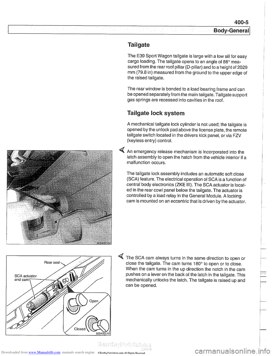
4 An emergency release mechanism is incorporated into the
latch assembly to open the hatch from the vehicle interior if a
malfunction occurs.
The tailgate lock assembly includes an automatic soft close
(SCA) feature. The electrical operation of SCA is a function of
central body electronics
(ZKE Ill). The SCA actuator is locat-
ed in the rear cowl panel below the tailgate. The actuator is
controlled by a load relay in the General Module. A locking
cam is mounted on an eccentric that is driven by the actuator.
4 The SCA cam always turns in the same direction to open or
close the tailgate. The cam turns
180" to open or to close.
When the cam turns in the up direction the notch in the cam
SCA actuator pushes on a lever on the back of the latch in the tailgate. This
mechanically unlocks the latch. The tailgate is raised up and
can be opened.
Page 803 of 1002
Downloaded from www.Manualslib.com manuals search engine
400-9
Body-General
Battery safety terminal
(BST)
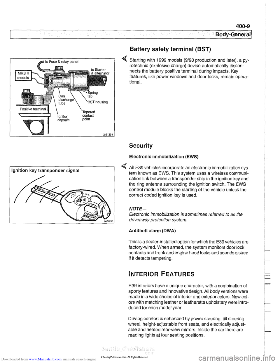
4 Starting with 1999 models (9198 production and later), a py-
rotechnic (explosive charge) device automatically discon-
nects the battery positive terminal during impacts. Key
features,
like power windows and door locks, remain opera-
tional.
Security
Electronic immobilization (EWS)
Ignition key transponder signal All
E39 vehicles incorporate an electronic immobilization sys-
tem known as EWS. This svstem uses a wireless comrnuni-
cation link between a transponder chip in the ignition key and
the ring antenna surrounding the ignition switch. The EWS
control module blocks the starting of the vehicle unless the
correct coded ignition key is used.
NOTE-
Electronic immobilization is sometimes referred to as the
driveaway protection system.
Antitheft alarm (DWA)
This is adealer-installed option for which the E39 vehicles are
factory-wired. When armed, the system monitors door
loci(
contacts and trunk and engine hood locks and sounds a siren
if it detects tampering.
E39 interiors have a unique character, with a combination
of
sporty features and innovativedesign. All body versions were
made in a wide choice of interior and exterior colors. New col-
ors with matching leather or leatherette upholstery were intro-
duced for each model year.
Driving
comfort is enhanced by power steering, tilt steering
wheel, height-adjustable front seats, and electrically adjust-
able and heated rear-view mirrors. Inside the car there are
reading lights at four seating positions.
Page 805 of 1002
Downloaded from www.Manualslib.com manuals search engine
Instrument cluster
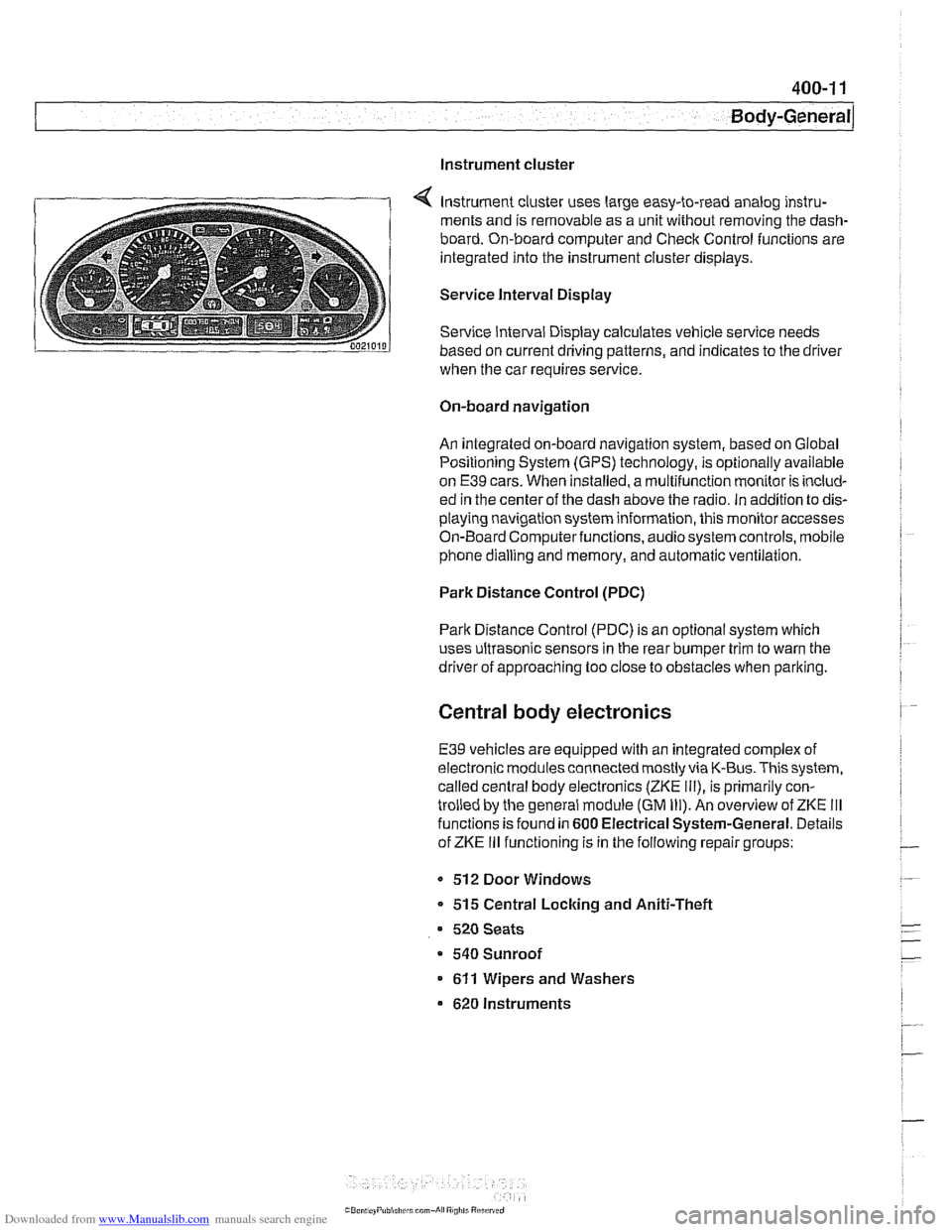
Instrument cluster uses large easy-to-read analog instru-
ments and is removable as a unit without removing the dash-
board. On-board computer and Check Control functions are
integrated into the instrument cluster displays.
Service Interval Display
Service Interval Display calculates vehicle service needs
based on current driving patterns, and indicates to the driver
when the car requires
service
On-board navigation
An integrated on-board navigation system, based on Global
Positioning System (GPS) technology, is optionally available
on
E39 cars. When installed, a multifunction monitor is includ-
ed in the center of the dash above the radio. in addition to dis-
playing navigation system information, this monitor accesses
On-Board Computerfunctions, audiosystem controls, mobile
phone dialling and memory, and automatic ventilation.
Park Distance Control (PDC)
Park Distance Control (PDC) is an optional system which
uses ultrasonic sensors in the rear bumper trim to warn the
driver of approaching too close to obstacles when parlting.
Central body electronics
E39 vehicles are equipped with an integrated complex of
electronic modules connected mostly via K-Bus. This system,
called central body electronics (ZKE
Ill), is primarily con-
trolled by the general module (GM
Ill). An overview of ZKE Ill
functions is found in 600 Electrical System-General. Details
of ZKE
Ill functioning is in the following repair groups:
- 512 Door Windows
* 515 Central Locking and Aniti-Theft
520 Seats
a 540 Sunroof
611 Wipers and Washers
620 Instruments
Page 880 of 1002
Downloaded from www.Manualslib.com manuals search engine
I lnterior Trim
This repair group covers interior trim removal and installation
procedures.
- Refer to the following repair groups for additional information:
250 Gearshift Linkage
41 1 Doors (interior door panels)
@ 612 Switches
620 Instruments
640 Heating and Air Conditioning [IHKA control panel!
650 Radio
721 Airbag System (SRS)
lnterior trim repairs
lnterior trim and finish panels are clipped or screwed into
place. Many of the trim retaining clips are designed
to be used
only once. When removing trim that is held in place with clips,
it is a good idea to have spare clips on hand before beginning
the job.
WARNING-
Special precautions must be observed when servicing the
BMWSupplementai Restraint System (SRS). Serious inju-
ry may result if system service is attempted by persons un-
familiar with the BMW
SRS and its approved service
procedures. BMW
speciiies that all inspection and service
should be performed by an authorized BMW
dealer.
Before performing any work involving airbags, discon-
nect the negative
() battery cable. See 721 Airbag
System (SRS).
Airbags contain a back-uppowersupply within the SRS
control module. A
5 second discharge period should be
allowed after the battery cable has been disconnected.
CAUTION-
* When working on electrical switclies or lights, always dis-
connect the negative
(-) cable from the battery and insu-
late the cable end to prevent accidental reconnection.
a Prior to disconnecting the battery, read the battery dis-
connection cautions given in
W1 General Warnings
and Cautions.
To prevent marring the trim when working on interior
components, work with plastic prying
tools or wrap the
tips of screwdrivers and pliers with tape before prying
Page 896 of 1002
Downloaded from www.Manualslib.com manuals search engine
51 5-2
/Central Locking and Anti-Theft
This section covers repair information for door, trunk and car-
go compartment locks, central locking, electronic
immob~liza-
tion (EWS) and anti-theft alarm (DWA).
€39 cars are equipped with sophisticated self-diagnostic elec-
trical systems. When experiencing malfunctions relating to
central locking. EWS or anti-theft systems, start the diagnosis
process using the
BMW service tester DIS, GT 1, MoDiC or
equivalent scan tool. An advanced diagnostic scan tool can
usually pinpoint electrical faults quickly and safely.
Additional electrical information can be found in:
610 Electrical Component Locations
ELE Electrical Wiring Diagrams
Central locking in E39 vehicles controls the door
locks, trunk
or tailgate lock and fuel filler flap lock. The control module for
the Central Body Electronics system (ZKE
Ill), lknown as the
General Module (GM
Ill), controls central locking.
ZKE
Ill manages the following central locking related func-
tions:
Central locking
* Keyless entry
Key memory
Power trunk release
Electric opening of tailgate
DWA alarm system
Diagnosis
General Module
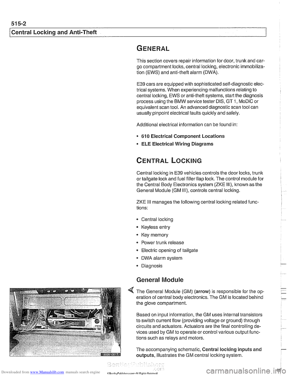
4 The General Module (GM) (arrow) is responsible for the op-
eration of central body electronics. The GM is located behind
the glove compartment.
Based on input information, the GM uses internal transistors
to switch current flow (providing voltage or ground) through
circuits and actuators. Actuators are the final controlling de-
vices used by GM to operate or control various output func-
tions such as relays and motors.
The accompanying schematic, Central locking inputs and
outputs, illustrates the GM central locking system.
Page 899 of 1002
Downloaded from www.Manualslib.com manuals search engine
Central Locking and Anti-Theft
DWA alarm
The DWA alarm system is
armedldisarmed when thevehicle
is locked / unlocked from either the door or trunk.
Convenience closing
I opening
The windows and sun roof can be closed or opened by hold-
ing the key in the
loclc I unlock position.
Crash sensor
The crash sensor is located in the left front
kick panel. It func-
tions by unlocking all doors in the event of an accident.
NOTE-
Continuous and repeated locliing / unlocking may cause
timedarrest of
the locliing system. When activated, the timed
arrest lasts for two minutes. The timed arrest does not affect
the crash sensor
unlocliing the doors in case of an accident.
Door locks
The driver's door lock location is the only point outside of the
vehicle where the ltey can mechanically control all of the cen-
tral locking system functions.
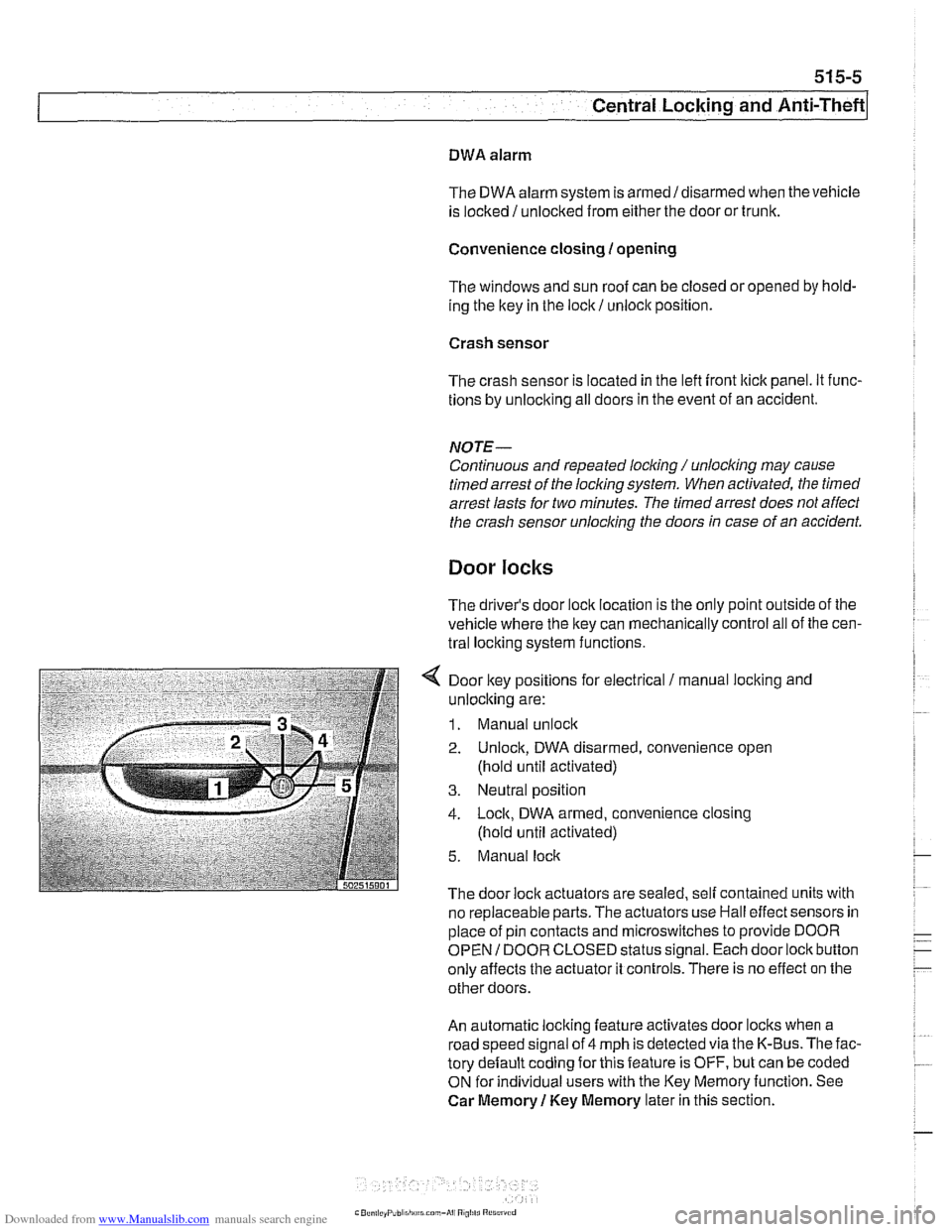
4 Door key positions for electrical / manual loclting and
unlocking are:
1. Manual unlock
2. Unlock, DWA disarmed, convenience open
(hold until activated)
3. Neutral position
4. Lock, DWA armed, convenience closing
(hold until activated)
5. Manual lock
The door lock actuators are sealed. self contained units with
no replaceable parts. The
actuators use Hall effect sensors in
place of pin contacts and microswitches to provide DOOR
OPEN
I DOOR CLOSED status signal. Each door lock button
only affects the actuator it controls. There is no effect on the
other doors.
An automatic locking feature activates door locks when a
road speed signal of 4 mph is detected via the K-Bus. The fac-
tory default coding for this feature is OFF, but can be coded
ON for individual users with the Key Memoryfunction. See
Car Memory
1 Key Memory later in this section.