transmission fluid BMW 528i 1997 E39 User Guide
[x] Cancel search | Manufacturer: BMW, Model Year: 1997, Model line: 528i, Model: BMW 528i 1997 E39Pages: 1002
Page 497 of 1002
Downloaded from www.Manualslib.com manuals search engine
176 Radiator and Cooling System
General ........................... .I7 0.2
Special tools
........................ .I7 0.2
Cooling system overview
(M52 TU shown. others similar) ......... .I7 0.3
Coolant pump
....................... .I7 0.3
Thermostat
......................... .I7 0.3
Mechanical thermostat (M52 engine)
..... .I7 0.4
Electrically heated thermostat
.......... .I7 0.4
Radiator and expansion tank
........... .I7 0.4
Mechanical cooling fan with viscous clutch
.I7 0.4
Electric (auxiliary) cooling fan ........... .I7 0.4
Transmission fluid heat exchanger
....... .I7 0.5
Warnings and cautions
................ .I7 0.7
Troubleshooting ................... .I7 0.7
Cooling system inspection
............. .I7 0.8
Cooling system pressure test
........... .I7 0.9
Combustion chamber leak test
......... .I7 0.10
Thermostat
........................ .I7 0.1 0
Cooling System Service ........... 170-10
Coolant. draining and filling
(6-cylinder models)
.................. 170-1 0
Coolant. draining and filling (V-8 models)
. 170-12
Cooling system. bleeding
............. 170-14
Mechanical (viscous clutch) cooling fan.
removing and installing
............... 170-14
Electric cooling fan.
removing and installing
............... 170-15
Thermostat. removing and installing
(M52engine) ....................... 170-16
Thermostat. removing and installing
(M52 TU or M54 engine) .............. 170-17
Thermostat. removing and installing (V-8 models)
....................... 170-1 8
Coolant pump. replacing (6-cylinder models)
.................. 170-1 9
Coolant pump. replacing (V-8 models) ... 170-20
Radiator. removing and installing
....... 170-22
Expansion tank. removing and
installing . . 170-24
Page 500 of 1002
Downloaded from www.Manualslib.com manuals search engine
-
I Radiator and Cooling System
Mechanical thermostat
(M52 engine)
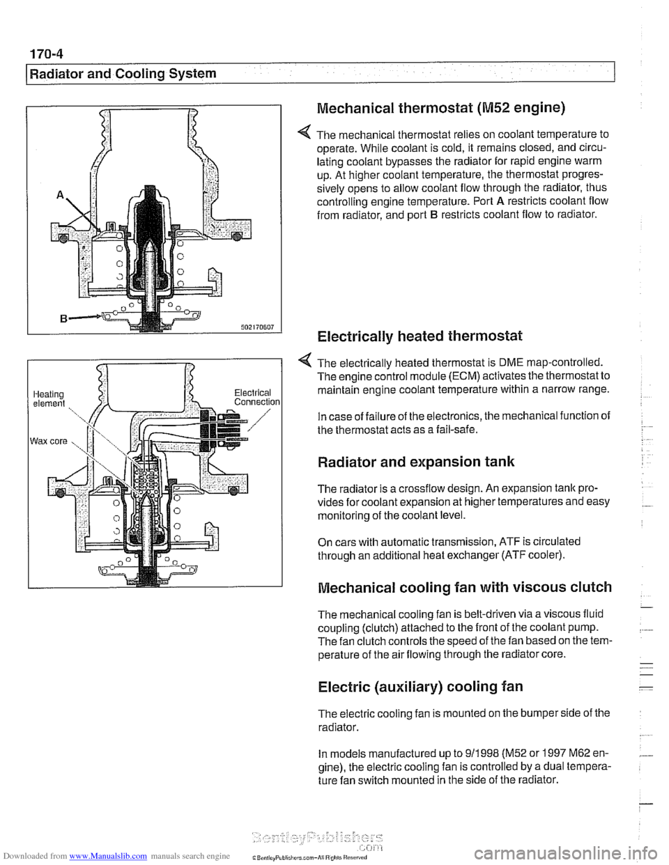
4 The mechanical thermostat relies on coolant temperature to
operate. While coolant is cold, it remains closed, and circu-
lating coolant bypasses the radiator for rapid engine warm
up. At higher coolant temperature, the thermostat progres-
sively opens to allow coolant flow through the radiator, thus
controlling engine temperature. Port
A restricts coolant flow
from radiator, and port
B restricts coolant flow to radiator.
Electrically heated thermostat
4 The electrically heated thermostat is DME map-controlled.
The engine control module (ECM) activates the thermostat to
maintain engine coolant temperature within a narrow range.
In case of failure of the electronics, the mechanical function of
the thermostat acts as a fail-safe.
Radiator and expansion tank
The radiator is a crossflow design. An expansion tank pro-
vides for coolant expansion at higher temperatures and easy
monitoring of the coolant level.
On cars with automatic transmission, ATF is circulated
through an additional heat exchanger (ATF cooler).
Mechanical cooling fan with viscous clutch
The mechanical cooling fan is belt-driven via a viscous fluid
coupling (clutch) attached to the front of the coolant pump.
The fan clutch controls the speed of the fan based on the tem-
perature of the air flowing through the radiator core.
Electric (auxiliary) cooling fan
The electric cooling fan is mounted on the bumper side of the
radiator.
In models manufactured up to
911 998 (M52 or 1997 M62 en-
gine), the electric cooling fan is controlled by a dual tempera-
ture fan switch mounted in the side of the radiator.
Page 501 of 1002
Downloaded from www.Manualslib.com manuals search engine
170-5
Radiator and Cooling System
Fan switch calibration (M52, M62 engine)
coniprairoi OUt rlgnal
Auto. ciimilte ~ontioi inpuls via CAN bus
Electric fan activation:
Low speed
91°C (196°F)
High speed 104' C (21 9' F)
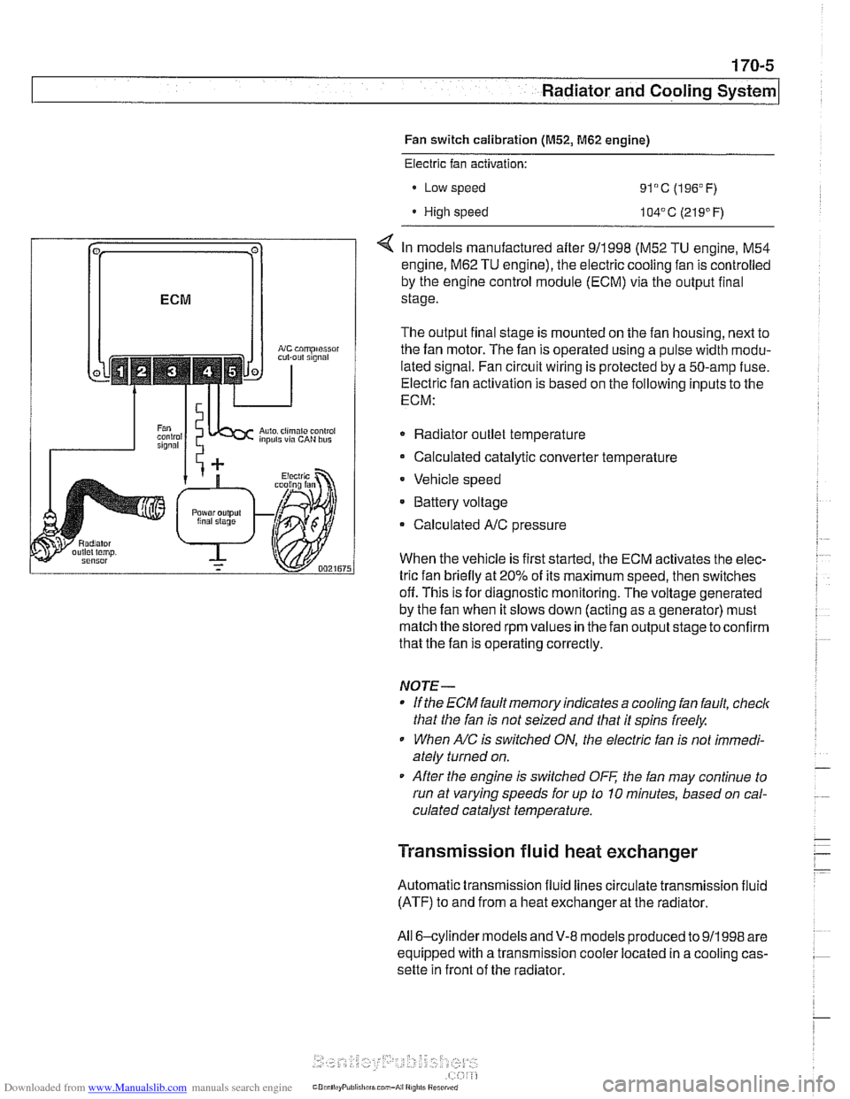
< In models manufactured after 911998 (M52 TU engine, M54
engine.
M62 TU engine), the electric cooling fan is controlled
by the engine control module (ECM) via the output final
stage.
The output final stage is mounted on the fan housing, next to
the fan motor. The fan is operated using a pulse width modu-
lated signal. Fan circuit wiring is protected by a 50-amp fuse.
Electric fan activation is based on the following inputs to the
ECM:
Radiator outlet temperature
Calculated catalytic converter temperature
Vehicle speed
* Battery voltage
Calculated
A/C pressure
When the vehicle is first started, the ECM activates the elec-
tric fan briefly at 20% of its maximum speed, then switches
off. This is for diagnostic monitoring. The voltage generated
by the fan when it slows down (acting as a generator) must
match the stored rpm values in the fan output stage toconfirm
that the fan is operating correctly.
NOTE-
If the ECM fault memory indicates a cooling fan fault, check
that the fan is not seized and that it spins freely.
When
A/C is switched ON, the electric fan is not immedi-
ately turned on.
After the engine is switched
OFF the fan may continue to
run at varying speeds for up to 10 minutes, based on cal-
culated catalyst temperature.
Transmission fluid heat exchanger
Automatic transmission fluid lines circulate transmission fluid
(ATF) to and from a heat exchanger at the radiator.
All 6-cylinder
models andV-8 models produced to 911998 are
equipped with a transmission cooler located in a cooling cas-
sette in front of the radiator.
Page 502 of 1002
Downloaded from www.Manualslib.com manuals search engine
.. - -
I Radiator and Cooling System
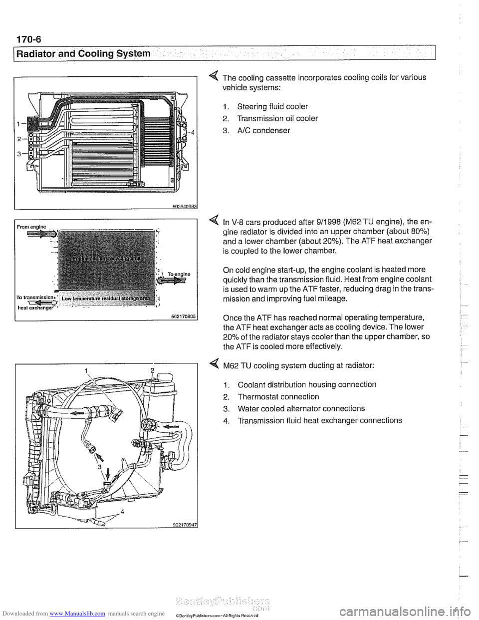
I I 4 The cooling cassette incorporates cooling coils for various
vehicle systems:
1. Steering fluid cooler
2. Transmission oil
coolel
3. AIC condenser
4 In V-8 cars produced after 911998 (M62 TU engine), the en-
gine radiator is divided into an upper chamber (about 80%)
and a lower chamber (about 20%). The ATF heat exchanger
is coupled to the lower chamber.
On cold engine start-up, the engine coolant is heated more
quicltly than the transmission fluid. Heat from engine coolant
is used to warm up the ATF faster, reducing drag in the trans-
mission and improving fuel mileage.
Once the ATF has reached normal operating temperature,
the ATF heat exchanger acts as cooling device. The lower
20% of the radiator
stays cooler than the upper chamber, so
the ATF is cooled more effectively.
4 M62 TU cooling system ducting at radiator:
1. Coolant distribution housing connection
2. Thermostat connection
3. Water cooled alternator connections
4. Transmission fluid heat exchanger connections
Page 542 of 1002
Downloaded from www.Manualslib.com manuals search engine
The lubricant used varies, depending on transmission and
model year. Fluid application information is clearly marked on
a label on transmission.
On manual transmission, either ATF (orange label reads
ATF-Oil) or a special BMW lubricant (yellow label reads MTF-
LT
I) is used. See 230 Manual Transmission.
Automatic transmission is filled with either Dexron
Ill ATF
(black transmission ID plate reads ATF-Oil), or special life-
time oil (green transmission ID plate reads Life-Time Oil). See
240 Automatic Transmission.
CAUTION--
If in doubt as to the type of fluid installed in a particular trans-
mission, consult an authorized
BMW dealer service depari-
ment for the latest in operating fluids.
Page 547 of 1002
Downloaded from www.Manualslib.com manuals search engine
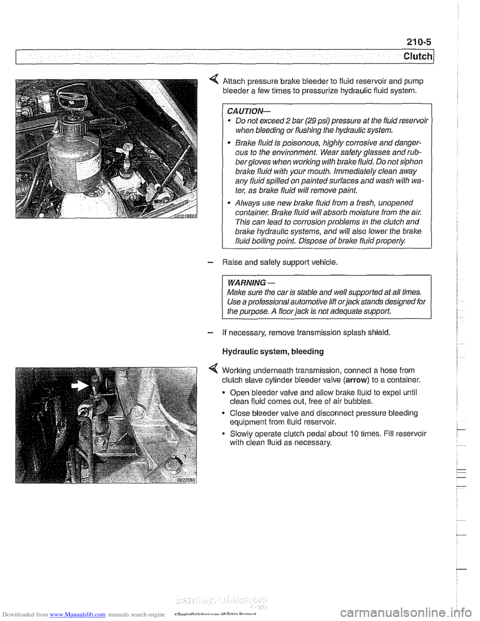
Anach pressure brake bleeder to fluid reservoir and pump
bleeder a few times to pressurize hydraulic fluid system.
CAUTION-
* Do not exceed 2 bar (29 psi) pressure at the fluid resenfoil
when bleeding or flushing the hydraulic system.
Brake fluid is poisonous, highly corrosive and danger-
ous to the environment. Wear safety glasses and
rub-
bergloves when working with brake fluid. Do not siphon
brale fluid with your mouth. Immediately clean away
any fluid spilled on painted surfaces and wash with wa-
ter, as brale fluid will remove paint.
Always use new brake fluid from a fresh, unopened
container.
Brake fluid will absorb moisture from the air.
This can lead to corrosion problems in the clutch and
brake hydraulic systems, ;nd will also lower the brake
fluid boiling point. Dispose of brale fluid properly.
- Raise and safely support vehicle.
WARNING-
Make sure the car is stable and well supported at all times.
Use a professional automotive lift orjackstands designed for
the purpose. A floor
iack is not adequate support.
- If necessary, remove transmission splash shield.
Hydraulic system, bleeding
Worlting underneath transmission, connect a hose from
clutch slave cylinder bleeder valve
(arrow) to a container.
Open bleeder valve and allow bralte fluid to expel until
clean fluid comes out, free of air bubbles.
Close bleeder valve and disconnect pressure bleeding
equipment from fluid reservoir.
Slowly operate clutch pedal about
10 times. Fill reservoir
with clean fluid as necessary.
CR* .,,, .rP,ll,h.:I,,~,~mn.lI","i,,i"
Page 548 of 1002
Downloaded from www.Manualslib.com manuals search engine
21 0-6
1 Clutch
Hydraulic system, bleeding
(using
BMW special tool 21 5 030)
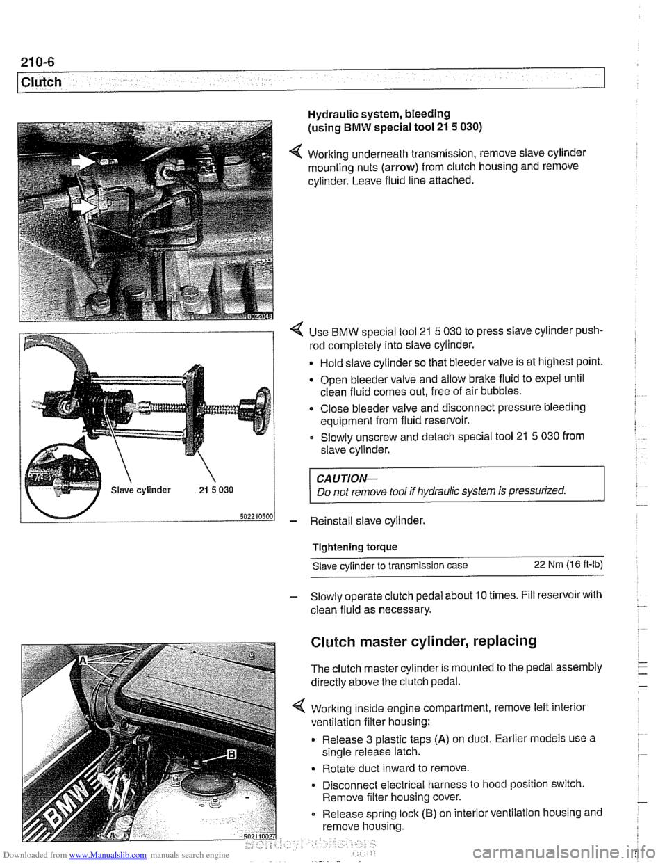
4 Working underneath transmission, remove slave cylinder
mounting nuts (arrow) from clutch housing and remove
cylinder. Leave fluid line attached.
4 Use BMW special tool 21 5 030 to press slave cylinder push-
rod completely into slave cylinder.
Hold slave cylinder so that bleeder valve is at highest point.
Open bleeder valve and allow brake fluid to expel until
clean fluid comes out, free of air bubbles.
* Close bleeder valve and disconnect pressure bleeding
equipment from fluid reservoir.
Slowly unscrew and detach special tool 21
5 030 from
slave cylinder.
CAUTION-
Do not remove tool if hydraulic system is pressurized.
- Reinstall slave cylinder.
Tightening torque Slave cylinder to transmission case
22 Nm (1 6 ft-lb)
- Slowly operate clutch pedal about 10 times. Fill reservoir with
clean fluid as necessary.
Clutch master cylinder, replacing
The clutch master cylinder is mounted to the pedal assembly
directly above the clutch pedal.
Working inside engine compartment, remove left interior
ventilation filter housing:
Release 3 plastic taps
(A) on duct. Earlier models use a
single release latch.
Rotate duct inward to remove
Disconnect electrical harness to hood position switch.
Remove filter housing cover.
Release spring
loclc (B) on interior ventilation housing and
remove housing.
Page 551 of 1002
Downloaded from www.Manualslib.com manuals search engine
- Raise and safely support vehicle
WARNING-
Make sure the car is stable and well supporied at all times.
Use a professional automotive /iff orjack stands designed for
the
ournose. A floor jack is not adeouate suooort.
- If necessary, remove transmission splash shield.
- Disconnect fluid line from slave cylinder on lefl side of trans-
mission. Place pan under hose to catch dripping fluid.
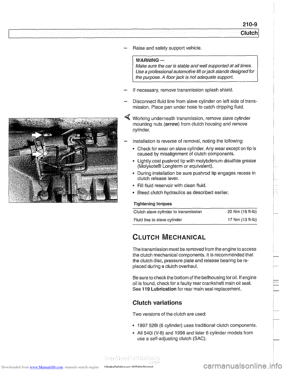
4 Working underneath transmission, remove slave cylinder
mounting nuts (arrow) from clutch housing and remove
cylinder.
- Installation is reverse of removal, noting the following:
Check for wear on slave cylinder. Any wear except on tip is
caused by misalignment of clutch components.
Lightly coat
pushrod tip with molybdenum disulfide grease
(MolyltoteIB Longterm or equivalent).
. During installation be sure pushrod tip engages recess in
clutch release lever.
Fill fluid reservoir with clean fluid.
. Bleed clutch hydraulics as described earlier.
Tightening
toraues - -.
Clutch slave cylinder to transmission 22 Nm (16 R-lb)
Fluid line to slave cylinder 17 Nm (13 ft-lb)
The transmission must be removed from the engine to access
the clutch mechanical components. It is recommended that
the clutch disc, pressure plate and release bearing be re-
placed during a clutch overhaul.
Besure tocheck the bottom of the bellhousing foroil. If engine
oil is found, check for a faulty rear crankshaft main oil seal.
See
119 Lubrication for rear main seal replacement.
Clutch variations
Two versions of the clutch are used:
1997 528i (6 cylinder) uses traditional clutch components.
All
540i (V-8) and 1998 and later 6 cylinder models from
use a self-adjusting clutch (SAC).
Page 563 of 1002
Downloaded from www.Manualslib.com manuals search engine
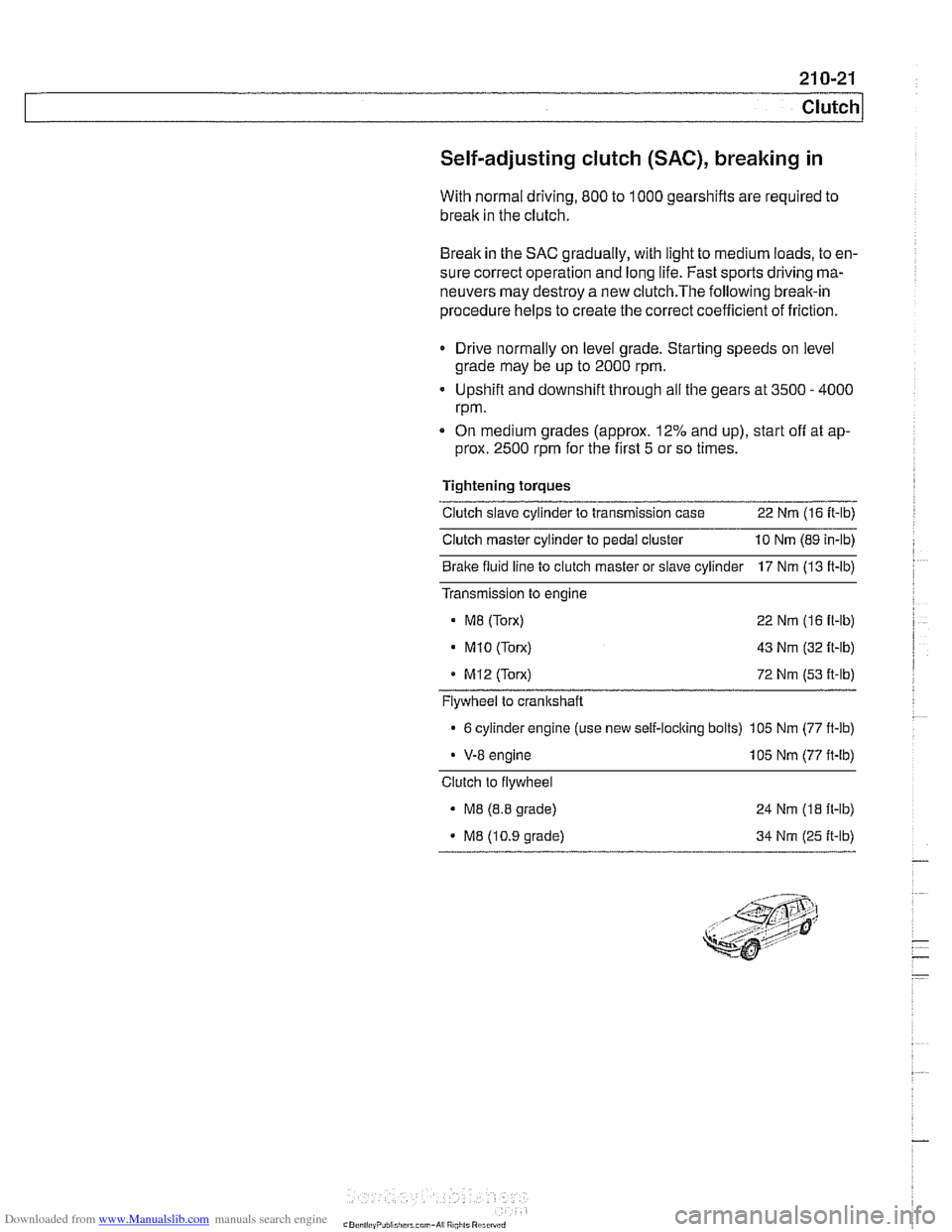
Self-adjusting clutch (SAC), breaking in
With normal driving, 800 to 1000 gearshifts are required to
break in the clutch.
Break in the SAC gradually, with light to medium loads, to en-
sure correct operation and long life. Fast sports driving ma-
neuvers may destroy a new
clutch.The following break-in
procedure helps to create the correct coefficient of friction.
Drive normally on level grade. Starting speeds on level
grade may be up to 2000 rpm.
Upshift and downshift through all the gears at 3500
- 4000
rpm.
On medium grades (approx. 12% and up), start
off at ap-
prox. 2500 rpm for the first 5 or so times.
Tightening torques
Clutch slave cylinder to transmission case 22 Nm (16 It-lb)
Clutch master cylinder to pedal cluster 10 Nm (89 in-lb)
Bralte fluid line to clutch master or slave cylinder 17 Nm (13 ft-lb)
Transmission to engine
M8 (Torx) 22 Nm (16 fl-lb)
. M1O (Torx) 43 Nm (32 ft-lb)
MI2 (Torx) 72 Nm (53 it-lb)
Flywheel to crankshaft
6 cylinder engine (use new self-loclting bolts) 105 Nm (77 ft-lb)
V-8 engine 105 Nm (77 ft-lb)
Clutch to flywheel
M8 (8.8 grade)
M8 (10.9 grade) 24
Nm
(18 ft-lb)
34 Nm (25 ft-lb)
Page 565 of 1002
Downloaded from www.Manualslib.com manuals search engine
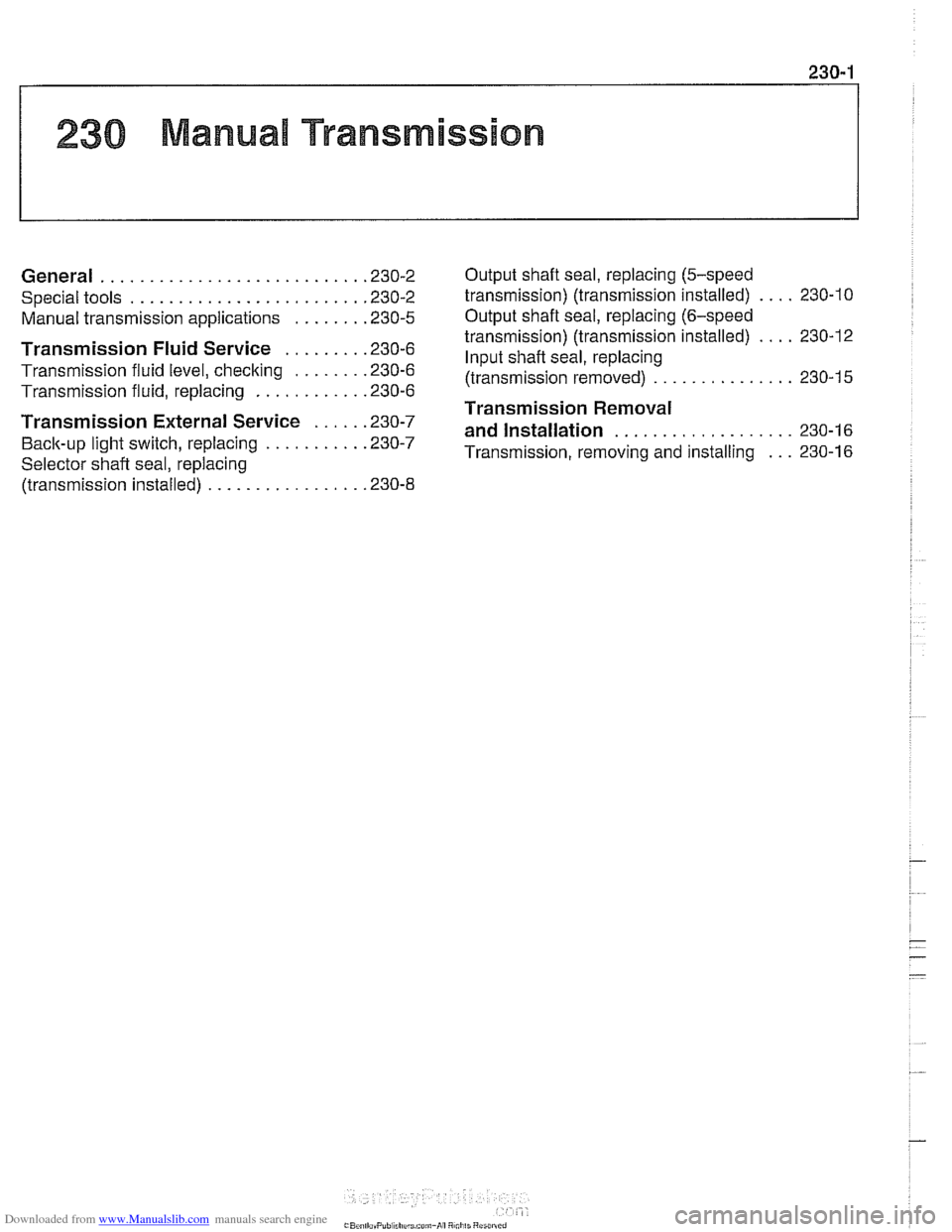
230 Manual Transmission
General ........................... .23 0.2 Output shaft
seal. replacing (5-speed
.... Special tools ........................ .23 0.2 transmission) (transmission installed) 230-10
Manual transmission aoolications ....... .23 0.5 Output shaft seal. replacing (6-speed . . .... transmission) (transmission installed) 230-12 ........ Transmission Fluid Service .23 0.6 put shaft seal. replacing
Transmission fluid level. checking ....... .23 0.6 (transmission ............... 230-15
........... Transmission fluid, replacing .23 0.6
Transmission Removal ................... ..... Transmission External Service .23 0-7 and installation 230-1
Back-up light switch, replacing .......... .23 0-' Transmission, removing and installing 230-16 ...
Selector shaft seal. reolacina .
(transmission installed) ................ .23 0.8