tailgate BMW 528i 1997 E39 Owner's Manual
[x] Cancel search | Manufacturer: BMW, Model Year: 1997, Model line: 528i, Model: BMW 528i 1997 E39Pages: 1002
Page 847 of 1002
Downloaded from www.Manualslib.com manuals search engine
Trunk Lid, Tailgate
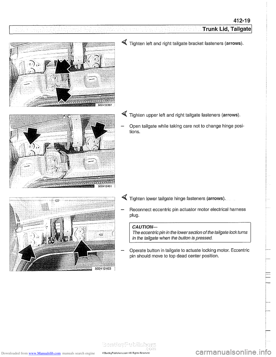
4 Tighten left and right tailgate bracket iasteners (arrows)
4 Tighten upper left and right tailgate fasteners (arrows).
- Open tailgate while taking care not to change hinge posi-
tions.
4 Tighten lower tailgate hinge fasteners (arrows)
- Reconnect eccentric pin actuator motor electrical harness
Plug.
CAUTION-
The eccentric pin in the lowersection of the tailgate loclc turns
in the tailgate when the button is pressed.
- Operate button in tailgate to actuate loclting motor. Eccentric
pin should move to top dead center position.
Page 848 of 1002
Downloaded from www.Manualslib.com manuals search engine
Trunk Lid, Tailgate
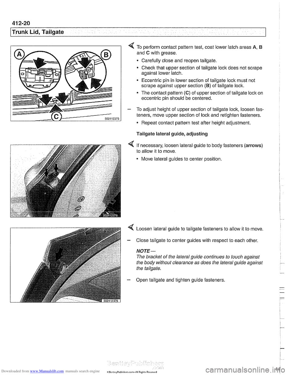
4 To periorm contact pattern test, coat lower latch areas A, 6
and C with grease.
Carefully close and reopen tailgate.
Check that upper section of tailgate lock does not scrape
against lower latch.
* Eccentric pin in lower section of tailgate loclc must not
scrape against upper section
(B) of tailgate lock.
The contact pattern (C) of upper section of tailgate lock on
eccentric pin should be centered.
- To adjust height of upper section of tailgate lock, loosen fas-
teners, move upper section of lock and retighten fasteners.
Repeat contact pattern test after height adjustment.
Tailgate lateral guide, adjusting
< If necessary, loosen lateral guide to body fasteners (arrows)
to allow it to move.
Move lateral guides to center position.
< Loosen lateral guide to tailgate fasteners to allow it to move.
- Close tailgate to center guides with respect to each other.
NOTE-
The bracket of the lateral guide continues to touch against
the body without clearance as does the lateral guide against
the tailgate.
- Open tailgate and tighten guide fasteners.
Page 849 of 1002
Downloaded from www.Manualslib.com manuals search engine
41 2-21
Trunk Lid, ~ailaatel
Rear window, adjusting
NOTE- Three versions of rear window are used on
Sport Wagon
models.
Tailgate must be correctly adjusted before rear window ad-
justments are made.
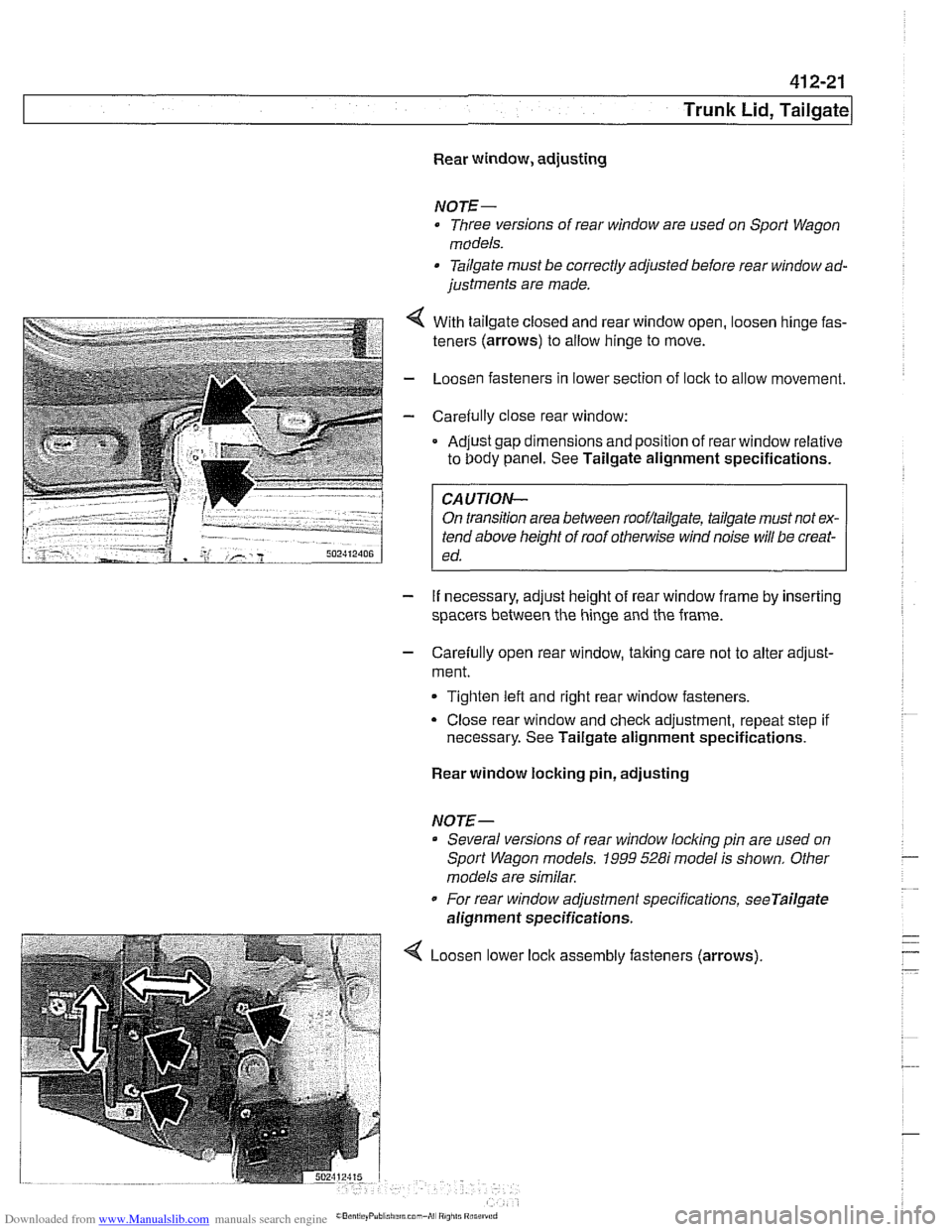
- . . . . . .. .. 4 With tailgate closeo ano rear window open, oosen ninge fas-
teners (arrows) to allow ninge to move.
- LoosL'n fasteners n lower section of ock to al ow movement.
- Care& ly c ose rear window:
Ad.~st gap dmensions and poston of rear window relative
to Oody panel. See Tailgate alignment specifications. .
FA-UTION- I
On transition area between rooflailgate, tailgate must not ex-
tend above height of roof
othe~lise wind noise will be creat-
ed.
- If necessary, adjust height of rear window frame by inserting
spacers between the hinge and the frame.
- Carefully open rear window, taking care not to alter adjust-
ment.
Tighten left and right rear window fasteners.
Close rear window and check adjustment, repeat step if
necessary. See Tailgate alignment specifications.
Rear window locking pin, adjusting
NOTE-- Several versions of rear window
locldng pin are used on
Sport Wagon models.
1999 528i model is shown. Other
models are similar.
For rear window adjustment specifications,
seeTailgate
alignment specifications.
Loosen lower assembly fasteners (arrows)
Page 850 of 1002
Downloaded from www.Manualslib.com manuals search engine
41 2-22
1 Trunk Lid, Tailgate
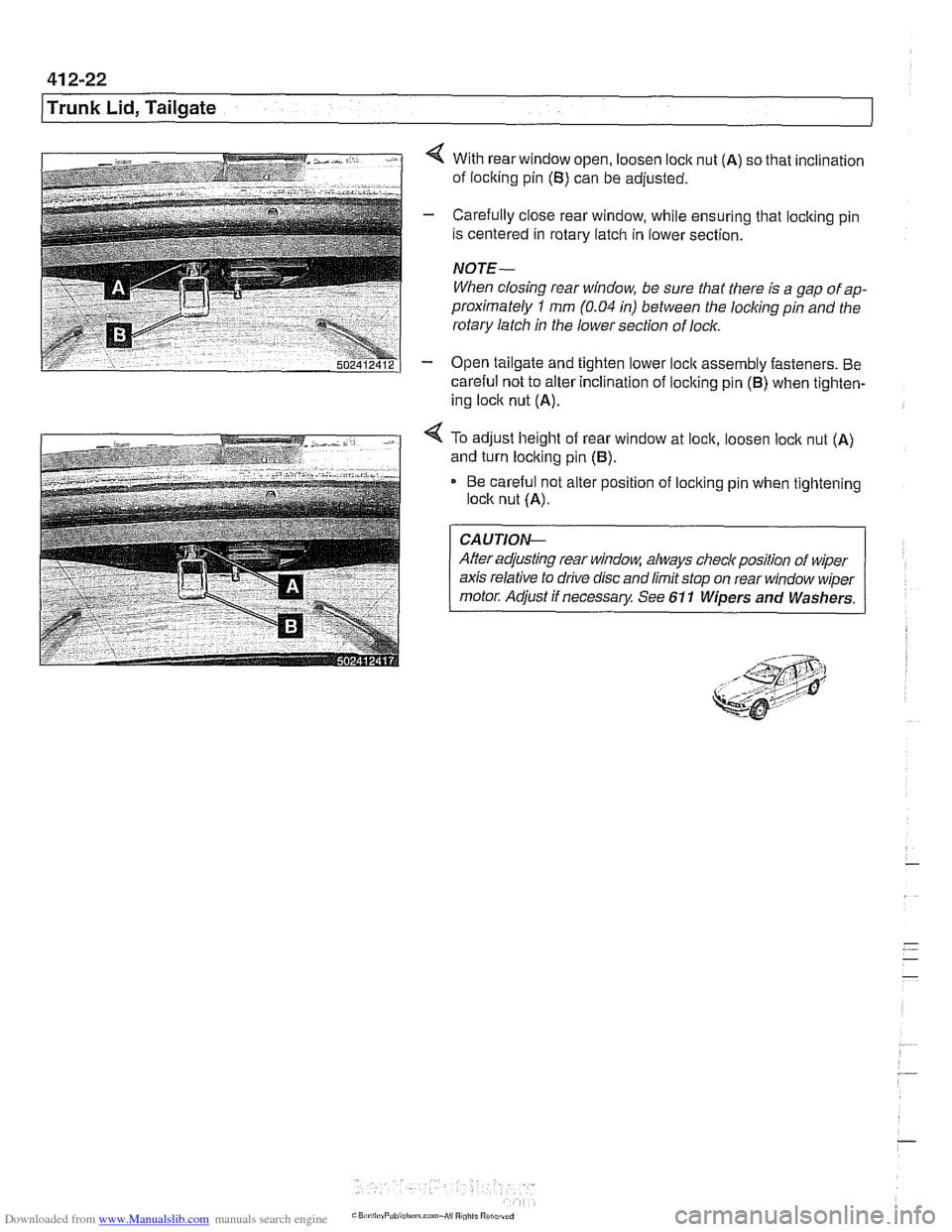
4 With rear window open, loosen loclc nut (A) so that inclination
of loclting pin
(B) can be adjusted.
- Carefully close rear window, while ensuring that locking pin
is centered in rotary latch in lower section.
NOTE-
When closing rear window, be sure that there is a gap of ap-
proximately
1 mm (0.04 in) between the locliing pin and the
rotary latch in the lower section of lock.
- Open tailgate and tighten lower loclc assembly fasteners. Be
careful not to alter inclination of loclting pin
(B) when tighten-
ing loclc nut
(A).
4 To adjust height of rear window at lock, loosen loclc nut (A)
and turn locking pin (B).
Be careful not alter position of loclting pin when tightening
lock nut
(A).
CA UTIOG
After adjusting rear window, always checlr position of wiper
axis relative to drive disc and limit stop on rear window wiper
motor. Adjust if necessary See 611 Wipers and Washers.
Page 895 of 1002
Downloaded from www.Manualslib.com manuals search engine
51 5 Central Locking and Anti-Theft
........................... General .51 5.2
Central Locking ................... .51 5.2
General Module
..................... .51 5.2
Central locking inputs and outputs
....... .51 5.3
Doorlocks
........................... 515-5
Trunklock
........................... 515-7
Remote entry (FZV)
.................. .51 5.7
Remote entry (FZV) inputs and outputs ... .51 5.8
Car Memory I Key Memory ............ .51 5.12
Trunk lid soft close (SCA)
............. .51 5.13
SCA subsystem
.................... .51 5.14
........ Tailgate and rear window locks
.51 5.14
Sport Wagon tailgate and rear
window
lock schematic ............... .51 5.15
Door Handles and Locks .......... .51 5.16
Door handle (outer), removing
and installing
....................... .51 5.16
Door latch, removing and installing
..... .51 5.17
Outer door lock cylinder, removing
and installing
....................... .51 5.18
Trunk Lock Assembly ............. 515-1 9
Trunk lock. removing and installing
...... 515-19
Trunk lock striker plate. removing
and installing
....................... 515-20
Tailgate lock. emergency release
....... 515-21
... Electronic Immobilization (EWS) 515-21
EWS variations
..................... 515-22
......... EWS control module. replacing 515-23
Transmitter
1 receiver module .......... 515-23
....................... Ring antenna 515-23
Anti-theft System (DWA) ........... 51 5-24
DWA LED Status
.................... 51 5-24
Tilt sensor
......................... 515-24
Interior protection .................... 51 5-25
Glass breakage sensors
.............. 515-26
Emergency disarming
................ 51 5-26
Page 896 of 1002
Downloaded from www.Manualslib.com manuals search engine
51 5-2
/Central Locking and Anti-Theft
This section covers repair information for door, trunk and car-
go compartment locks, central locking, electronic
immob~liza-
tion (EWS) and anti-theft alarm (DWA).
€39 cars are equipped with sophisticated self-diagnostic elec-
trical systems. When experiencing malfunctions relating to
central locking. EWS or anti-theft systems, start the diagnosis
process using the
BMW service tester DIS, GT 1, MoDiC or
equivalent scan tool. An advanced diagnostic scan tool can
usually pinpoint electrical faults quickly and safely.
Additional electrical information can be found in:
610 Electrical Component Locations
ELE Electrical Wiring Diagrams
Central locking in E39 vehicles controls the door
locks, trunk
or tailgate lock and fuel filler flap lock. The control module for
the Central Body Electronics system (ZKE
Ill), lknown as the
General Module (GM
Ill), controls central locking.
ZKE
Ill manages the following central locking related func-
tions:
Central locking
* Keyless entry
Key memory
Power trunk release
Electric opening of tailgate
DWA alarm system
Diagnosis
General Module
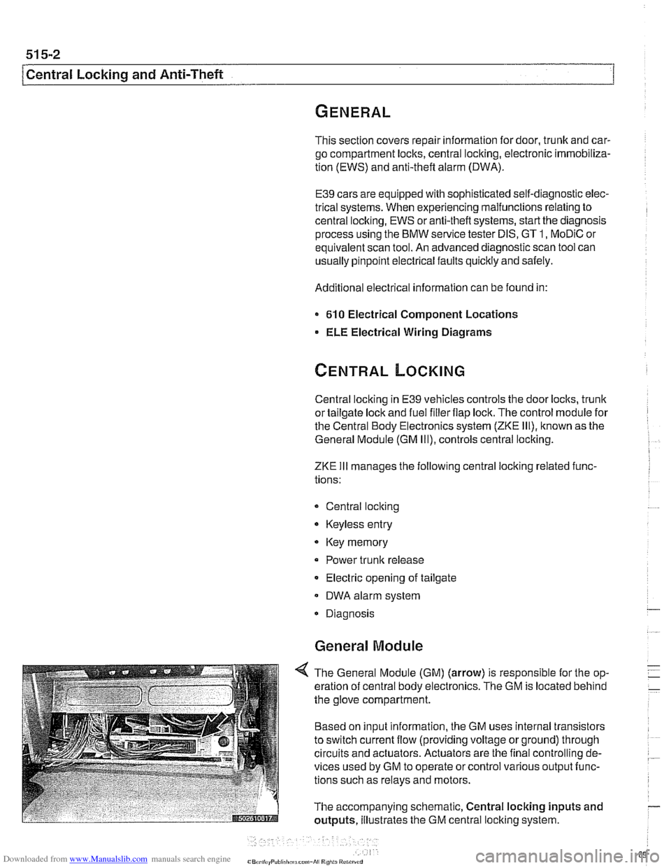
4 The General Module (GM) (arrow) is responsible for the op-
eration of central body electronics. The GM is located behind
the glove compartment.
Based on input information, the GM uses internal transistors
to switch current flow (providing voltage or ground) through
circuits and actuators. Actuators are the final controlling de-
vices used by GM to operate or control various output func-
tions such as relays and motors.
The accompanying schematic, Central locking inputs and
outputs, illustrates the GM central locking system.
Page 898 of 1002
Downloaded from www.Manualslib.com manuals search engine
51 5-4
I Central Locking and Anti-Theft
Driver's door lock
The
lock/unlock signals are sent as input to the door module
from two microswitches on the lockcylinder. The driver's door
module carries out the locking
/ unlocking functions of the
driver's door through its final stage control.
The signal to lock the remaining doors, trunk or tailgate and
fuel flap is sent over the P-Bus to the GM and the passenger
door module. Activation of the passengers door
loclt is carried
out by the passenger door module. The rear doors, trunlt or
tailgate and fuel flap are
locked by the f~nal stage in the GM.
When
locked from the outside, all doors are set to the double
lock position and the GM will not carry out any unlock com-
mands from the central
loclc button or remote trunk release
button.
Selective unlocking
When unlocking with the key or the remote transmitter, the
first unloclcrequestwill only unlock the driver'sdoor. A second
unlock request will unlock the remaining doors, trunk or tail-
gate and fuel flap.
Trunk locking
I
The vehicle can be locked/unlocked from the trunlc loclc cylin-
der. The GM locks the trunk or tailgate, rear doors and fuel fill-
er. The locking command is passed over the P-Bus to the
respective door modules to lock the driver's and passengers
doors.
Locking the trunk and removing the key in the
hor~zontal posi-
tion will set the valet lock and prevent opening of the trunlt
with the central locking system.
Central locking switch
-
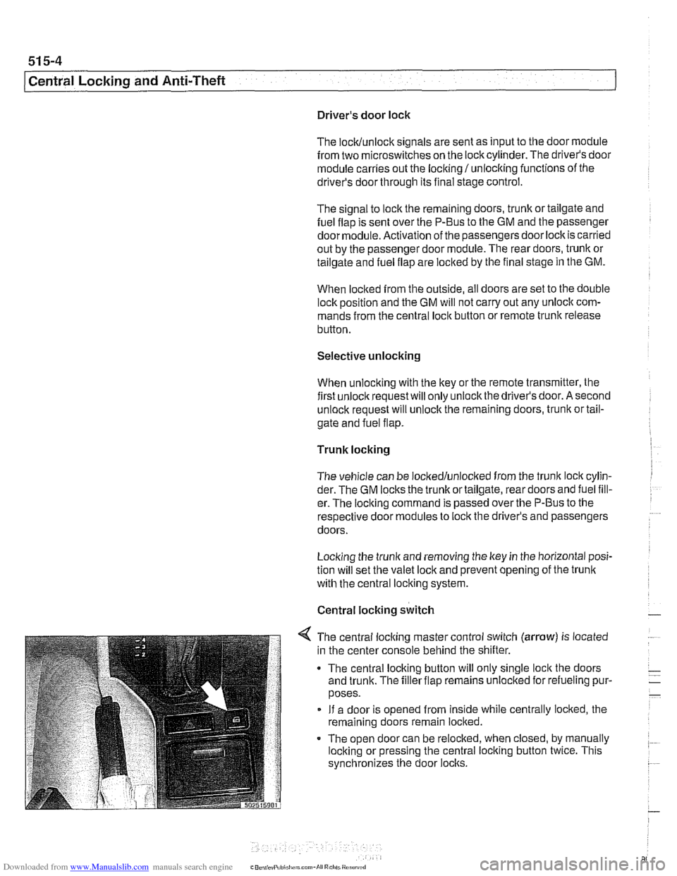
< The central locking master control switch (arrow) is located
in the center console behind the shifter.
The central locking button will only single
loclt the doors
and trunk. The filler flap remains unloclted for refueling pur-
poses.
If a door is opened from inside while centrally locked, the
remaining doors remain locked.
The open door can be relocked, when closed, by manually
locking or pressing the central locking button twice. This
synchronizes the door
locks.
Page 901 of 1002
Downloaded from www.Manualslib.com manuals search engine
Central Locking and Anti-Theft
Trunk lock
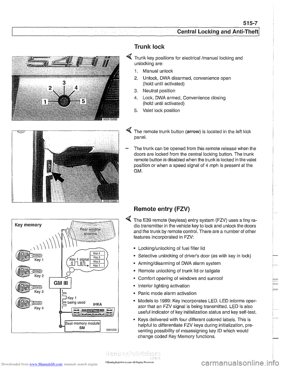
6 Tr~nk ftey pos~rions for eecir'cal mama, locking and
-nlock~ng are:
1. Manual unock .. - - - ........ - ..- .- ................. s.=.=-- 2. Unlock. DWA oisarmed, conven:ence open
(nold
un1:l aclivaledj
3. Ne~tral posit'on
1. -ocn. DWA armeo, Convenience closng
(hold ~nti activated)
5. Valet .oc,t position
. -- .............-... .- . - -.....
Key memory
< The remote trunk button (arrow) is located in the lefl lticlc
panel.
- The trunk can be opened from this remote release when the
doors are locked from the central locking button. The
trunk
remote button is disabled when the trunkis loclted in the valet
position or when a speed signal of
4 mph is present at the
GM.
Remote entry (FZV)
< The €39 remote (keyless) entry system (FZV) uses a tiny ra-
dio transmitter in the vehicle key to
lock and unlock the doors
and the trunk by remote control. There are a number of other
features incorporated in FZV:
Locltinglunloclting of fuel filler lid
Selective unlocking of driver's door (as with key in lock)
Armingldisarming of DWA alarm system
Remote unlocking of
trunk lid or tailgate
Comfort opening of windows and sunroof
* Interior lighting activation
Panic mode alarm activation
* Models to 1999: Key incorporates LED. LED informs oper-
ator that an FZV signal is being transmitted. LED is also
useful indicator of key initialization status and lkey self-test.
Keys delivered with four different colored labels. This is
helpful to differentiate FZV keys during initialization,
pre.
venting possibility of misassigning key ID which would
change coded Key Memory functions.
Page 902 of 1002
Downloaded from www.Manualslib.com manuals search engine
515-8
/Central Locking and Anti-Theft
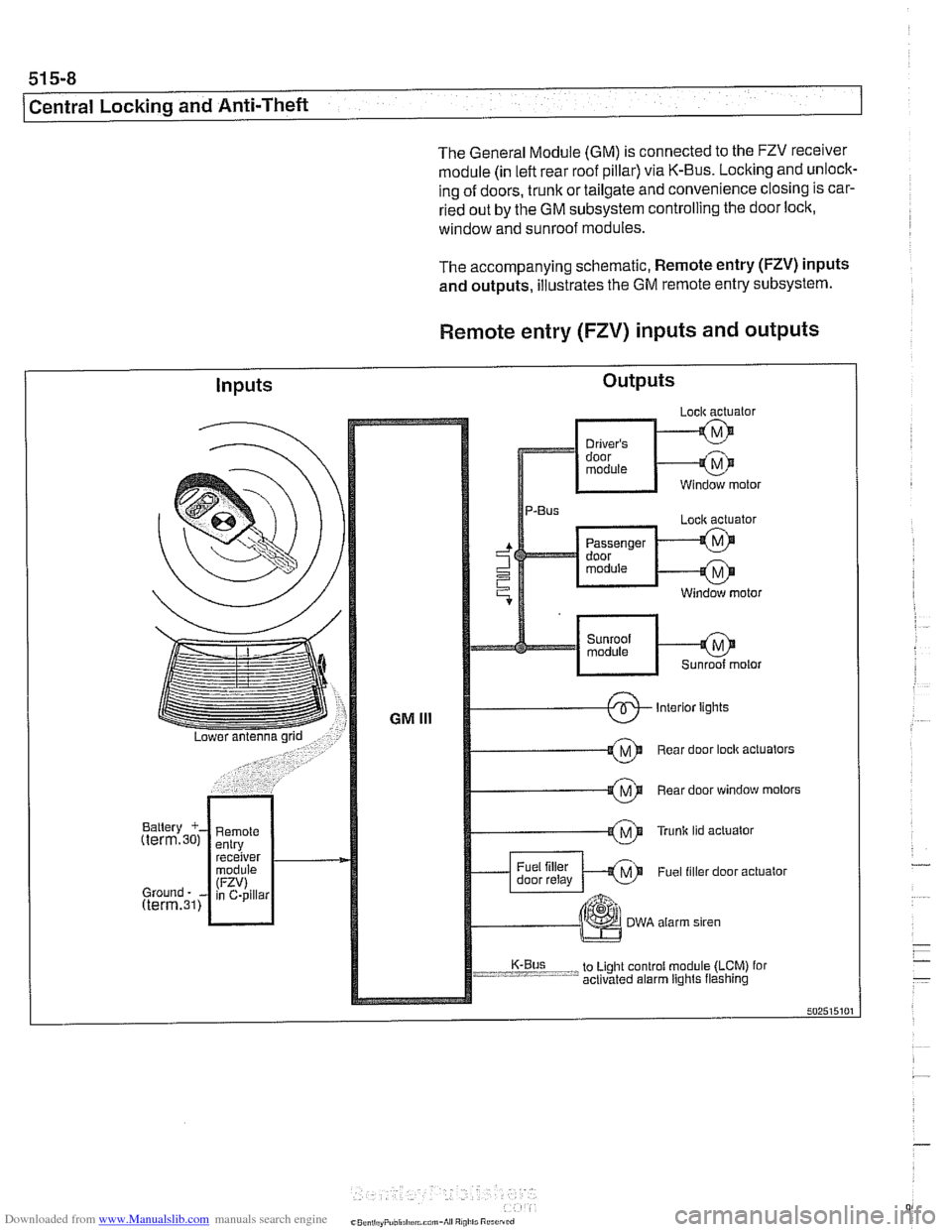
The General Module (GM) is connected to the FZV receiver
module (in left rear roof pillar) via K-Bus. Locking and unlock-
ing of doors, trunk or tailgate and convenience closing is car-
ried out by the GM subsystem controlling the door lock,
window and sunroof modules.
The accompanying schematic, Remote entry
(FZV) inputs
and outputs, illustrates the GM remote entry subsystem.
Remote entry (FZV) inputs and outputs
Inputs Outputs
Page 908 of 1002
Downloaded from www.Manualslib.com manuals search engine
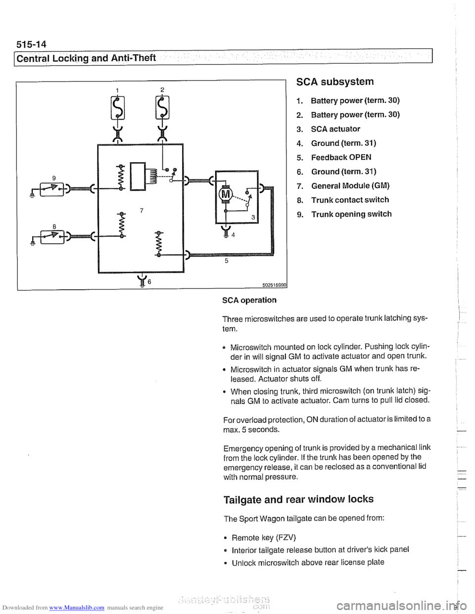
SCA subsystem
1. Battery power (term. 30)
2. Battery power (term. 30)
3. SCA actuator
4. Ground (term. 31)
5. Feedback OPEN
6. Ground (term. 31)
7. General Module (GM)
8. Trunk contact switch
9. Trunk opening switch
502515990
SCA operation
Three microswitches are used to operate trunk latching sys-
tem.
Microswitch mounted on lock cylinder. Pushing lock cylin-
der in will signal GM to activate actuator and open trunk.
Q Microswitch in actuator signals GM when trunlc has re-
leased. Actuator shuts off.
When closing trunk, third microswitch (on trunk latch) sig-
nals GM to activate actuator. Cam turns to pull lid closed.
Foroverload protection,
ON duration of actuator is limited to a
max.
5 seconds.
Emergency opening of trunk is provided by a mechanical link
from the lockcylinder.
If the trunlc has been opened by the
emergency release, it can be
reclosed as a conventional lid
with normal pressure.
Tailgate and rear window locks
The Sport Wagon tailgate can be opened from:
0 Remote lkey (FZV)
Interior tailgate release button at driver's lkick panel
Unlock microswitch above rear license plate